CN212812516U - Automatic electrical control box capable of dissipating heat quickly - Google Patents

Automatic electrical control box capable of dissipating heat quickly Download PDF

Info

Publication number
CN212812516U
CN212812516U CN202022051169.3U CN202022051169U CN212812516U CN 212812516 U CN212812516 U CN 212812516U CN 202022051169 U CN202022051169 U CN 202022051169U CN 212812516 U CN212812516 U CN 212812516U
Authority
CN
China
Prior art keywords
box body
box
heat dissipation
electrical control
baffle
Prior art date
Legal status (The legal status is an assumption and is not a legal conclusion. Google has not performed a legal analysis and makes no representation as to the accuracy of the status listed.)
Active
Application number
CN202022051169.3U
Other languages
Chinese (zh)
Inventor
周敏峰
Current Assignee (The listed assignees may be inaccurate. Google has not performed a legal analysis and makes no representation or warranty as to the accuracy of the list.)
Dai Wenjun
Shen Zhiqun
Yang Lu Yu
Zheng Lele
Original Assignee
Zhangjiagang City Xi'en Automation Equipment Co ltd
Priority date (The priority date is an assumption and is not a legal conclusion. Google has not performed a legal analysis and makes no representation as to the accuracy of the date listed.)
Filing date
Publication date
Application filed by Zhangjiagang City Xi'en Automation Equipment Co ltd filed Critical Zhangjiagang City Xi'en Automation Equipment Co ltd
Priority to CN202022051169.3U priority Critical patent/CN212812516U/en
Application granted granted Critical
Publication of CN212812516U publication Critical patent/CN212812516U/en
Active legal-status Critical Current
Anticipated expiration legal-status Critical

Links

Images

Landscapes

  • Devices That Are Associated With Refrigeration Equipment (AREA)

Abstract

本实用新型公开了一种快速散热的自动化电气控制箱,包括下箱体和上箱体,所述下箱体和上箱体之间设置有分隔板,所述下箱体内部底端设置有绝缘板,所述绝缘板上端表面设置控制电板,所述控制电板顶端表面设置有半导体制冷器,所述分隔板底端表面中部设置有第二风扇,所述上箱体两侧内部位于第二通风口处设置有挡板,所述挡板表面设置有挡条。本实用新型在下箱体底部设置了半导体制冷器,当箱体温度超过设定阈值时,半导体制冷器开设工作,同时气缸带动挡板向下移动,使档条与第二通风口相重合,用于密封箱体使冷空气无法流失出箱外,从而加快箱体内部温度的降低,提高散热效率和散热效果,从而有效提高了元器件的散热保护效果。
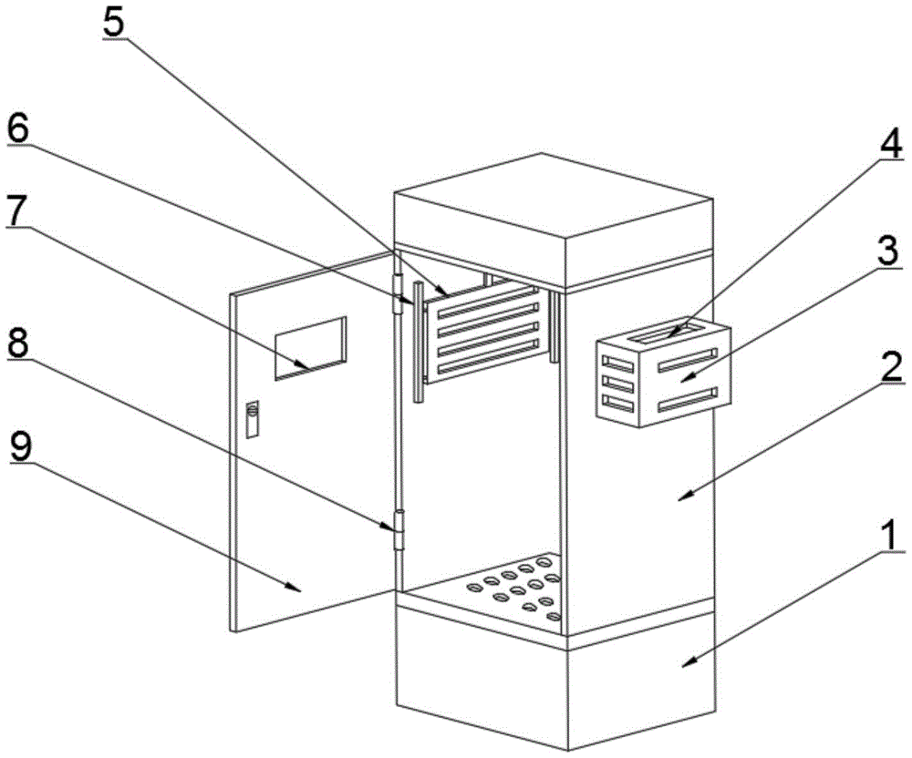
Figure 202022051169

The utility model discloses an automatic electrical control box with rapid heat dissipation, which comprises a lower box body and an upper box body, a partition plate is arranged between the lower box body and the upper box body, and a bottom end inside the lower box body is arranged There is an insulating plate, the upper surface of the insulating plate is provided with a control board, the top surface of the control board is provided with a semiconductor refrigerator, the middle of the bottom surface of the partition board is provided with a second fan, and the two sides of the upper box are provided with A baffle is arranged inside the second vent, and a baffle is arranged on the surface of the baffle. The utility model is provided with a semiconductor refrigerator at the bottom of the lower box body. When the temperature of the box body exceeds the set threshold, the semiconductor refrigerator is opened to work, and at the same time, the air cylinder drives the baffle plate to move downward, so that the baffle bar and the second vent are coincident, and the use of Because of the sealed box body, the cold air cannot be lost out of the box, thereby accelerating the reduction of the internal temperature of the box body, improving the heat dissipation efficiency and heat dissipation effect, thereby effectively improving the heat dissipation protection effect of the components.

Figure 202022051169

Description

Automatic electrical control box capable of dissipating heat quickly
Technical Field
The utility model relates to a control box technical field, concretely relates to can quick radiating automatic electrical control box.
Background
The electrical control box is formed by assembling switch equipment, measuring instruments, protective electrical appliances and auxiliary equipment in a closed or semi-closed metal cabinet or on a screen according to the electrical wiring requirement. The electric control box is internally provided with a plurality of electric appliance elements, and the temperature inside the box body is overhigh due to long-time uninterrupted work operation, especially when summer comes, so that the potential safety hazard is great, and the service life of the electric control box is also shortened.
The existing general heat dissipation device for the electrical control box is a heat dissipation fan, but the heat dissipation of the heat dissipation fan is slow, so that the heat dissipation efficiency of the electrical control box cannot be effectively improved, and the heat dissipation protection effect on components is reduced.
SUMMERY OF THE UTILITY MODEL
An object of the utility model is to provide a radiating automatic electrical control box fast to the radiator fan heat dissipation who proposes in solving above-mentioned background is slow, can not effectively improve electrical control box's radiating efficiency, thereby has reduced the heat dissipation protection effect problem to components and parts.
In order to achieve the above object, the utility model provides a following technical scheme: the utility model provides a quick radiating automatic electrical control box, includes box and last box down, box fixed mounting is at last box bottom surface down, be provided with the division board down between box and the last box, the inside bottom of box is provided with the insulation board down, insulation board upper end surface sets up the control electroplax, control electroplax top surface is provided with the semiconductor refrigeration ware, division board bottom surface middle part is provided with the second fan, a plurality of through-holes have been seted up on the division board surface, go up box both sides upper end and seted up the second ventilation opening, it is provided with the baffle to go up inside second ventilation opening department that is located of box both sides, the baffle surface is provided with the blend stop.
Preferably, the inside both sides of upper box are located baffle upper end fixed mounting and have the cylinder, the cylinder output is provided with the connecting block, connecting block bottom and baffle top fixed surface are connected, the cylinder passes through connecting block and cylinder fixed connection.
Preferably, the upper box body is internally provided with slide rails in threaded connection with two sides of the baffle, the slide rails are in sliding connection with the baffle, and the baffle is slidably arranged inside the upper box body through the slide rails.
Preferably, the upper end of one side of the upper box body is in threaded connection with a mounting box at the second vent, a first fan is arranged inside the mounting box, and a first vent is formed in the surface of the mounting box.
Preferably, one side of the upper box body is rotatably connected with a box door, the box door is rotatably connected with the upper box body through a rotating shaft, and the middle part of the upper end of the box door is provided with an observation window.
Preferably, a temperature sensor is arranged inside the top end of the upper box body.
Preferably, the temperature sensor and the semiconductor refrigerator are electrically connected with the control electric board.
Compared with the prior art, the utility model provides a but quick radiating automatic electrical control box possesses following beneficial effect:
the utility model discloses bottom half has set up the semiconductor cooler under, when the box temperature exceeded and has set for the threshold value, the work was seted up to the semiconductor cooler, and the cylinder drives the baffle downstream simultaneously, makes shelves strip and second ventilation opening coincide mutually for sealed box makes the unable loss of cold air go out the case outside, thereby accelerates the reduction of the inside temperature of box, improves radiating efficiency and radiating effect, thereby has effectively improved the heat dissipation protection effect of components and parts.
Drawings
The accompanying drawings are included to provide a further understanding of the invention, and are incorporated in and constitute a part of this specification, illustrate embodiments of the invention, and together with the description, do not constitute a limitation of the invention, in which:
fig. 1 is a schematic view of a three-dimensional structure of an automatic electrical control box capable of dissipating heat rapidly according to the present invention;
fig. 2 is a cross-sectional view of an automatic electrical control box capable of dissipating heat rapidly according to the present invention;
in the figure: 1. a lower box body; 2. an upper box body; 3. mounting a box; 4. a first vent; 5. a baffle plate; 6. a slide rail; 7. an observation window; 8. a rotating shaft; 9. a box door; 10. an insulating plate; 11. a control panel; 12. a semiconductor refrigerator; 13. a first fan; 14. a partition plate; 15. a through hole; 16. a second fan; 17. a second vent; 18. blocking strips; 19. a cylinder; 20. a temperature sensor; 21. and (4) connecting the blocks.
Detailed Description
The technical solutions in the embodiments of the present invention will be described clearly and completely with reference to the accompanying drawings in the embodiments of the present invention, and it is obvious that the described embodiments are only some embodiments of the present invention, not all embodiments. Based on the embodiments in the present invention, all other embodiments obtained by a person skilled in the art without creative work belong to the protection scope of the present invention.
In the description of the present invention, it should be noted that the terms "center", "upper", "lower", "left", "right", "front", "rear", "vertical", "horizontal", "inner", "outer", and the like indicate orientations or positional relationships based on the orientations or positional relationships shown in the drawings, and are only for convenience of description and simplification of description, but do not indicate or imply that the device or element referred to must have a specific orientation, be constructed in a specific orientation, and be operated, and thus, should not be construed as limiting the present invention. Furthermore, the terms "first," "second," and "third" are used for descriptive purposes only and are not to be construed as indicating or implying relative importance.
Referring to fig. 1-2, the present invention provides a technical solution: an automatic electrical control box capable of quickly dissipating heat comprises a lower box body 1 and an upper box body 2, wherein the lower box body 1 is fixedly arranged on the bottom end surface of the upper box body 2, a partition plate 14 is arranged between the lower box body 1 and the upper box body 2, the lower box body 1 is fixedly connected with the upper box body 2 through the partition plate 14, an insulation plate 10 is arranged at the bottom end in the lower box body 1, a control electric plate 11 is arranged on the upper end surface of the insulation plate 10, a semiconductor refrigerator 12 is arranged on the top end surface of the control electric plate 11, a second fan 16 is arranged in the middle of the bottom end surface of the partition plate 14, a plurality of through holes 15 are formed in the surface of the partition plate 14, cold air generated by the semiconductor refrigerator 12 is blown to the interior of the upper box body 2 through the through holes 15 formed in the partition plate 14 by the second fan 16, the heat dissipation speed in the interior of the box body is accelerated, so that the heat dissipation efficiency is improved, the surface of the baffle 5 is provided with a barrier strip 18, and the barrier strip 18 is matched with the size of the second ventilation opening 17.
Go up inside both sides of box 2 and be located 5 upper ends fixed mounting of baffle and have cylinder 19, cylinder 19 also with control electroplax 11 electric connection, when the incasement temperature surpasss control electroplax 11 and sets for the threshold value, cylinder 19 works, drive baffle 5 through connecting block 21 and remove, make blend stop 18 and the coincidence of second ventilation opening, thereby make the form feel the box and be in encapsulated situation, cylinder 19 output is provided with connecting block 21, connecting block 21 bottom and 5 top fixed surface of baffle are connected, cylinder 19 passes through connecting block 21 and 19 fixed connection of cylinder, it has slide rail 6 to be located 5 both sides threaded connection of baffle inside 2 of last box, slide rail 6 and 5 sliding connection of baffle, baffle 5 passes through slide rail 6 sliding mounting inside last box 2, baffle 18 passes through slide rail 6 and slides down under the effect of cylinder 19.
Go up 2 one sides upper ends of box and be located second ventilation opening 17 threaded connection and have mounting box 3, the inside first fan 13 that is provided with of mounting box 3, first ventilation opening 4 has been seted up on mounting box 3 surface, first fan 13 also with control electroplax 11 electric connection, when the incasement temperature does not surpass control electroplax 11 and sets for the threshold value, the inside air of 2 inside upper boxes and outside air exchange convection current are gone up in the work of first fan 13 to this lets the inside circulation of air of 2 upper boxes, thereby reduces the inside temperature of box.
Go up box 2 one side and rotate and be connected with chamber door 9, chamber door 9 rotates through pivot 8 and last box 2 to be connected, and chamber door 9 upper end middle part is provided with observation window 7, conveniently observes the inside condition of going up box 2.
A temperature sensor 20 is arranged inside the top end of the upper box 2. For monitoring the temperature inside the upper case 2 and transmitting a signal to the control electric board 11, and the temperature sensor 20 and the semiconductor refrigerator 12 are electrically connected to the control electric board 11.
The utility model discloses a theory of operation and use flow: the utility model discloses install the back, when the box temperature does not surpass the threshold value that control electroplax 11 set for, first fan 13 work, first vent 4 and second vent 17 through the setting make incasement air and outside air form the convection current, make incasement temperature reduce with natural air temperature, when the incasement temperature surpasss control electroplax 11 and sets for the threshold value, cylinder 19 drives baffle 5 downstream through connecting block 21, make shelves 18 and the coincidence of second vent 17, can't run off the case with the cold air that box seal made semiconductor refrigerator 12 produce, then semiconductor refrigerator 12 begins work, the cold air that second fan 16 produced semiconductor refrigerator 12 distributes everywhere at the box with higher speed, thereby accelerate the reduction of the inside temperature of box, raise the radiating efficiency and radiating effect, thereby effectively improved the heat dissipation protection effect of components and parts.
Although embodiments of the present invention have been shown and described, it will be appreciated by those skilled in the art that changes, modifications, substitutions and alterations can be made in these embodiments without departing from the principles and spirit of the invention, the scope of which is defined in the appended claims and their equivalents.

Claims (7)

1.一种快速散热的自动化电气控制箱,包括下箱体(1)和上箱体(2),其特征在于:所述下箱体(1)固定安装在上箱体(2)底端表面,所述下箱体(1)和上箱体(2)之间设置有分隔板(14),所述下箱体(1)内部底端设置有绝缘板(10),所述绝缘板(10)上端表面设置控制电板(11),所述控制电板(11)顶端表面设置有半导体制冷器(12),所述分隔板(14)底端表面中部设置有第二风扇(16),所述分隔板(14)表面开设有多个通孔(15),所述上箱体(2)两侧上端开设有第二通风口(17),所述上箱体(2)两侧内部位于第二通风口(17)处设置有挡板(5),所述挡板(5)表面设置有挡条(18)。1. An automatic electrical control box for rapid heat dissipation, comprising a lower box body (1) and an upper box body (2), characterized in that: the lower box body (1) is fixedly installed on the bottom end of the upper box body (2) A partition plate (14) is arranged between the lower box body (1) and the upper box body (2), an insulating plate (10) is arranged at the inner bottom end of the lower box body (1), and the insulation A control electric plate (11) is arranged on the upper end surface of the plate (10), a semiconductor refrigerator (12) is arranged on the top surface of the control electric plate (11), and a second fan is arranged in the middle of the bottom end surface of the partition plate (14). (16), a plurality of through holes (15) are formed on the surface of the partition plate (14), second vents (17) are formed on the upper ends of both sides of the upper box (2), and the upper box (2) 2) A baffle plate (5) is arranged on the inside of the two sides at the second ventilation opening (17), and a baffle strip (18) is arranged on the surface of the baffle plate (5). 2.根据权利要求1所述的一种快速散热的自动化电气控制箱,其特征在于:所述上箱体(2)内部两侧位于挡板(5)上端固定安装有气缸(19),所述气缸(19)输出端设置有连接块(21),所述连接块(21)底端与挡板(5)顶端表面固定连接,所述气缸(19)通过连接块(21)与气缸(19)固定连接。2. An automatic electrical control box for rapid heat dissipation according to claim 1, characterized in that: both sides of the upper box (2) are fixedly installed with a cylinder (19) at the upper end of the baffle plate (5), so The output end of the air cylinder (19) is provided with a connecting block (21), the bottom end of the connecting block (21) is fixedly connected with the top surface of the baffle plate (5), and the air cylinder (19) is connected to the air cylinder (21) through the connecting block (21). 19) Fixed connection. 3.根据权利要求1所述的一种快速散热的自动化电气控制箱,其特征在于:所述上箱体(2)内部位于挡板(5)两侧螺纹连接有滑轨(6),所述滑轨(6)与挡板(5)滑动连接,所述挡板(5)通过滑轨(6)滑动安装在上箱体(2)内部。3. The automatic electrical control box for rapid heat dissipation according to claim 1, wherein the upper box (2) is located on both sides of the baffle plate (5) and is threadedly connected with slide rails (6), so The sliding rail (6) is slidably connected with the baffle plate (5), and the baffle plate (5) is slidably installed inside the upper box body (2) through the sliding rail (6). 4.根据权利要求1所述的一种快速散热的自动化电气控制箱,其特征在于:所述上箱体(2)一侧上端位于第二通风口(17)处螺纹连接有安装盒(3),所述安装盒(3)内部设置有第一风扇(13),所述安装盒(3)表面开设有第一通风口(4)。4. The automatic electrical control box for rapid heat dissipation according to claim 1, wherein the upper end of one side of the upper box body (2) is located at the second vent (17) and is threadedly connected with a mounting box (3). ), a first fan (13) is arranged inside the installation box (3), and a first ventilation port (4) is opened on the surface of the installation box (3). 5.根据权利要求1所述的一种快速散热的自动化电气控制箱,其特征在于:所述上箱体(2)一侧转动连接有箱门(9),所述箱门(9)通过转轴(8)与上箱体(2)转动连接,所述箱门(9)上端中部设置有观察窗(7)。5. The automatic electrical control box for rapid heat dissipation according to claim 1, wherein a box door (9) is rotatably connected to one side of the upper box body (2), and the box door (9) passes through The rotating shaft (8) is rotatably connected with the upper box body (2), and an observation window (7) is arranged in the middle of the upper end of the box door (9). 6.根据权利要求1所述的一种快速散热的自动化电气控制箱,其特征在于:所述上箱体(2)顶端内部设置有温度传感器(20)。6 . The automatic electrical control box with rapid heat dissipation according to claim 1 , wherein a temperature sensor ( 20 ) is arranged inside the top of the upper box ( 2 ). 7 . 7.根据权利要求6所述的一种快速散热的自动化电气控制箱,其特征在于:所述温度传感器(20)和半导体制冷器(12)与控制电板(11)电性连接。7 . The automatic electrical control box for rapid heat dissipation according to claim 6 , wherein the temperature sensor ( 20 ) and the semiconductor refrigerator ( 12 ) are electrically connected to the control board ( 11 ). 8 .
CN202022051169.3U 2020-09-18 2020-09-18 Automatic electrical control box capable of dissipating heat quickly Active CN212812516U (en)

Priority Applications (1)

Application Number Priority Date Filing Date Title
CN202022051169.3U CN212812516U (en) 2020-09-18 2020-09-18 Automatic electrical control box capable of dissipating heat quickly

Applications Claiming Priority (1)

Application Number Priority Date Filing Date Title
CN202022051169.3U CN212812516U (en) 2020-09-18 2020-09-18 Automatic electrical control box capable of dissipating heat quickly

Publications (1)

Publication Number Publication Date
CN212812516U true CN212812516U (en) 2021-03-26

Family

ID=75089662

Family Applications (1)

Application Number Title Priority Date Filing Date
CN202022051169.3U Active CN212812516U (en) 2020-09-18 2020-09-18 Automatic electrical control box capable of dissipating heat quickly

Country Status (1)

Country Link
CN (1) CN212812516U (en)

Cited By (2)

* Cited by examiner, † Cited by third party
Publication number Priority date Publication date Assignee Title
CN112004391A (en) * 2020-09-18 2020-11-27 张家港市西恩自动化设备有限公司 An automatic electrical control box that can quickly dissipate heat
CN118785644A (en) * 2024-07-22 2024-10-15 苏州新亚科技有限公司 A touch-control integrated machine that is easy to maintain

Similar Documents

Publication Publication Date Title
CN210957472U (en) Double-cooling self-cooling type power distribution box
CN112004391A (en) An automatic electrical control box that can quickly dissipate heat
CN210779759U (en) Electrical control cabinet convenient to heat dissipation
CN211017818U (en) High-efficient radiating switch board
CN206100785U (en) An automation system control cabinet
CN219106866U (en) Switch board with ventilation mechanism
CN221380177U (en) Automatic control by temperature change formula switch board
CN213462766U (en) High temperature resistant combination formula switch board
CN218920828U (en) Heat abstractor of equipment control cabinet
CN214901810U (en) Based on computer network equipment is with protection against electric shock subassembly
CN214379584U (en) All-insulation fixed-interval enclosed low-voltage switch cabinet
CN211266210U (en) Step-by-step switching control cabinet with good heat dissipation performance
CN211429848U (en) An electrical cabinet with both sealing performance and heat dissipation effect
CN213341195U (en) Electrical control cabinet with explosion-proof function
CN212413683U (en) Communication cabinet heat dissipation device
CN209948374U (en) Control cabinet based on air cooling technology
CN116073246A (en) Waterproof heat dissipation switch board
CN214757618U (en) Be used for dustproof specialty rack of miniature data center silence
CN214958195U (en) Novel control cabinet
CN207588312U (en) A kind of power distribution cabinet with strong heat dissipation effect
CN215600796U (en) High-voltage board heat abstractor
CN211908156U (en) High-efficient radiating high tension switchgear
CN221812228U (en) A transformer electrical cabinet
CN219419875U (en) Novel low-voltage wire feeding cabinet
CN220043982U (en) An air guide device for transmission equipment

Legal Events

Date Code Title Description
GR01 Patent grant
GR01 Patent grant
TR01 Transfer of patent right

Effective date of registration: 20250522

Address after: 213300 Jiangsu Province Changzhou City Liyang City Kunlun Street Huqiao Village Committee Pailou Village No. 37

Patentee after: Dai Wenjun

Country or region after: China

Patentee after: Zheng Lele

Patentee after: Shen Zhiqun

Patentee after: Yang Lu Yu

Address before: 215600 Zhangjiagang City, Suzhou City, Jiangsu Province, Chen Dongzhuang Village, Yangshe Town, Zhangjiagang City, Zhangjiagang Xien Automation Equipment Co., Ltd.

Patentee before: ZHANGJIAGANG CITY XI'EN AUTOMATION EQUIPMENT CO.,LTD.

Country or region before: China

TR01 Transfer of patent right