Outdoor power distribution cabinet with self-locking function
Technical Field
The utility model relates to a switch board specifically is an outdoor switch board with self-locking function.
Background
The distribution cabinet (case) is a final-stage device of a distribution system and is divided into a power distribution cabinet (case), a lighting distribution cabinet (case) and a metering cabinet (case). The power distribution cabinet is a general name of a motor control center. The power distribution cabinet is used in the occasions with dispersed loads and less loops; the motor control center is used for occasions with concentrated loads and more loops. They distribute the power of a certain circuit of the upper-level distribution equipment to the nearby loads. This level of equipment should provide protection, monitoring and control of the load.
The existing outdoor power distribution cabinet does not have the self-locking function, when the power distribution cabinet is maintained, an operator often forgets to carry a key of the power distribution cabinet to open the cabinet door, so that the maintenance efficiency is reduced, and the working time is wasted.
SUMMERY OF THE UTILITY MODEL
An object of the utility model is to provide an outdoor switch board with self-locking function to solve the problem that proposes among the above-mentioned background art.
In order to achieve the above object, the utility model provides a following technical scheme:
an outdoor power distribution cabinet with a self-locking function comprises a base, wherein a cabinet is fixedly connected to the top of the base, movable plates are arranged on two sides of the inner wall of the cabinet, two ends of each movable plate are respectively connected with sliding grooves formed in two sides of the inner wall of the cabinet in a sliding mode through sliding blocks, lead screws are symmetrically arranged in the cabinet and respectively penetrate through the movable plates longitudinally, the top ends of the lead screws are rotatably connected with the top of the inner wall of the cabinet through bearing seats, fixed rods are fixedly connected with the bottom of the inner wall of the cabinet through the bearing seats, first belt discs are sleeved on the fixed rods, a motor is symmetrically and fixedly connected to the bottom of the base, an output shaft of the motor vertically penetrates through the base and the cabinet and extends into the cabinet, a second belt disc is sleeved on the output shaft of the motor, and the second, the improved cabinet door is characterized in that a threaded through hole for threaded connection of a lead screw is formed in the movable plate, a limiting rod is fixedly connected to the top of the movable plate, a box body is fixedly connected to the top of the box body, the top of the limiting rod vertically penetrates through the box body and extends into the box body, a box door is hinged to the front side of the box body through a hinge, a limiting plate is fixedly connected to the inner side of the box door, a through hole for the limiting rod to pass through is formed in the limiting plate, an observation window is arranged on the surface of the box door, a door handle is arranged on the surface of the box door, fans are symmetrically and fixedly connected to the top and the bottom of the inner wall of the box.
As a further aspect of the present invention: the top of the box body is fixedly connected with a waterproof shed through two support rods.
As a further aspect of the present invention: the box body is provided with heat dissipation holes at the top, and the top of each heat dissipation hole is fixedly connected with a second dust screen, and the two sides of the box body are provided with heat dissipation holes and heat dissipation hole outer sides fixedly connected with first dust screens.
As a further aspect of the present invention: anticollision institution includes anticollision board, slide bar, sleeve and spring, anticollision board outside fixedly connected with rubber pad, the inboard symmetry fixedly connected with slide bar of anticollision board, the slide bar transversely runs through the sleeve and extends to in the sleeve, the slide bar extends to the one end fixedly connected with spring one end in the sleeve, spring other end fixed connection is in sleeve inner wall one side, sleeve one end and box fixed connection.
As a further aspect of the present invention: the base bottom symmetry is seted up flutedly, recess inner wall fixedly connected with electric putter, electric putter's push rod one end fixedly connected with movable block, the movable block bottom articulates through the pivot has connecting rod one end, the connecting rod other end has the movable rod through pivot fixedly connected with, and movable rod bottom fixed mounting has the universal wheel, and the movable rod top is through pivot and base bottom fixed connection.
As a further aspect of the present invention: the fan, the motor and the electric push rod are electrically connected with the switch through wires, and the switch is electrically connected with an external power supply through wires.
Compared with the prior art, the beneficial effects of the utility model are that:
1. when the chamber door was closed, start two motors simultaneously for the second belt pulley passes through belt drive and drives first belt pulley and rotate, thereby further drive the lead screw and take place to rotate, the rotation of lead screw drives the movable plate and drives the gag lever post rebound, the gag lever post passes the through-hole that sets up on the limiting plate on the chamber door this moment, thereby realize the function of switch board auto-lock, when needs open the chamber door, make gag lever post and limiting plate phase separation, be convenient for open the chamber door, thereby realize that operating personnel need not to hand-carry the key can the opening device overhaul.
2. Through the setting of fan, can all-roundly dispel the heat in to the box, avoid the electrical components of high temperature harm switch board body, further improve the radiating efficiency through the louvre that sets up on the box, inside first dust screen and the second dust screen that set up on the louvre effectively avoided the dust to get into the box, played dirt-proof effect.
3. Through the setting of waterproof canopy, avoid outdoor sleet weather to drench the device, lead to the damage of the inside electrical components of device, improve the life of device.
4. Through the setting of anticollision institution, receive the striking and extrude its device of spring and play the effect of buffering when the anticollision board, further strengthen the protection electrical components.
5. When the device needs to be moved, the electric push rod is started, so that the electric push rod pushes the sliding block to move, the connecting rod is further driven to push the universal wheel to move downwards until the universal wheel is contacted with the ground, and the device is convenient to move.
Drawings
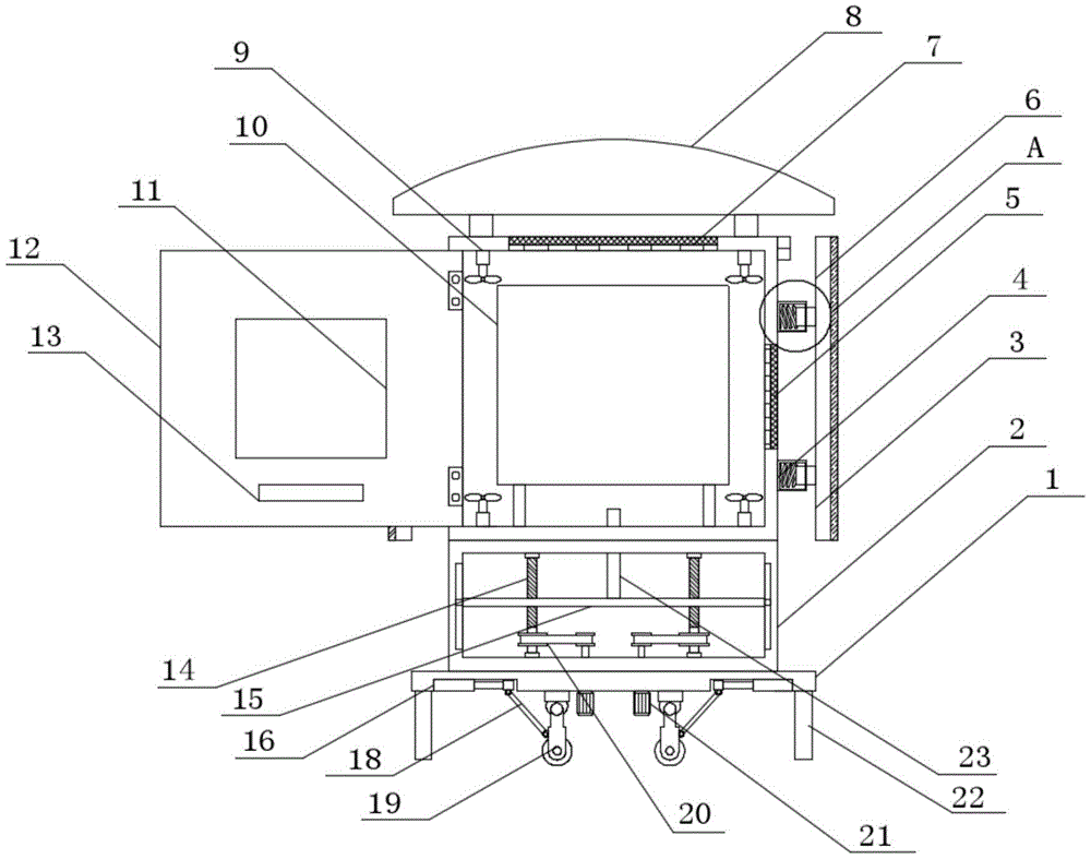
Fig. 1 is a schematic structural diagram of an outdoor power distribution cabinet with a self-locking function.
Fig. 2 is a schematic structural diagram of a in an outdoor power distribution cabinet with a self-locking function.
Fig. 3 is a schematic structural diagram of an outdoor power distribution cabinet with a self-locking function in a front view.
Shown in the figure: the anti-collision device comprises a base 1, a case 2, an anti-collision plate 3, a case body 4, a first dustproof net 5, an anti-collision mechanism 6, a second dustproof net 7, a waterproof shed 8, a fan 9, a power distribution cabinet body 10, an observation window 11, a case door 12, a limiting plate 13, a lead screw 14, a movable plate 15, an electric push rod 16, a connecting rod 18, a universal wheel 19, a belt 20, a motor 21, a supporting rod 22, a limiting rod 23, a sliding rod 24, a sleeve 25 and a spring 26.
Detailed Description
The technical solutions in the embodiments of the present invention will be described clearly and completely with reference to the accompanying drawings in the embodiments of the present invention, and it is obvious that the described embodiments are only some embodiments of the present invention, not all embodiments. Based on the embodiments in the present invention, all other embodiments obtained by a person skilled in the art without creative work belong to the protection scope of the present invention.
Referring to fig. 1 to 3, in the embodiment of the present invention, an outdoor power distribution cabinet with a self-locking function includes a base 1, a cabinet 2, an anti-collision plate 3, a cabinet 4, a first dust screen 5, an anti-collision mechanism 6, a second dust screen 7, a waterproof shed 8, a fan 9, a power distribution cabinet body 10, an observation window 11, a cabinet door 12, a limiting plate 13, a lead screw 14, a moving plate 15, an electric push rod 16, a connecting rod 18, a universal wheel 19, a belt 20, a motor 21, a supporting rod 22, a limiting rod 23, a sliding rod 24, a sleeve 25 and a spring 26, wherein the top of the base 1 is fixedly connected with the cabinet 2, the moving plate 15 is disposed on two sides of the inner wall of the cabinet 2, two ends of the moving plate 15 are slidably connected with sliding grooves disposed on two sides of the inner wall of the cabinet 2 through sliders, the lead screws 14 are symmetrically disposed in the cabinet 2, the two lead screws 14, the bottom end of the lead screw 14 is fixedly connected with a fixed rod, the fixed rod is fixedly connected with the bottom of the inner wall of the case 2 through a bearing seat, a first belt pulley is sleeved on the fixed rod, the bottom of the base is symmetrically and fixedly connected with a motor 21, an output shaft of the motor 21 vertically penetrates through the base 1 and the case 2 and extends into the case 2, a second belt pulley is sleeved on the output shaft of the motor 21, the second belt pulley is in transmission connection with the first belt pulley through a belt 20, a threaded through hole for threaded connection of the lead screw 14 is formed in the movable plate 15, a limiting rod 23 is fixedly connected to the top of the movable plate 15, a case body 4 is fixedly connected to the top of the case 2, the top end of the limiting rod 23 vertically penetrates through the case 2 and the case body 4 and extends into the case body 4, a case door 12 is hinged to the front side, the limiting plate 13 is provided with a through hole for the limiting rod 23 to pass through, the surface of the box door 12 is provided with an observation window 11, the surface of the box door 12 is provided with a door handle, the top and the bottom of the inner wall of the box body 4 are symmetrically and fixedly connected with a fan 9, the bottom of the inner wall of the box body 4 is fixedly connected with a power distribution cabinet body 10 through two supporting rods, the top of the box body 4 is fixedly connected with a waterproof shed 8 through two supporting rods, the top of the box body 4 is provided with heat dissipation holes, the top of each heat dissipation hole is fixedly connected with a second dustproof net 7, two sides of the box body 4 are provided with heat dissipation holes, the outer sides of the heat dissipation holes are fixedly connected with a first dustproof net 5, two sides of the box body 4 are provided with anti-collision mechanisms 6, each anti-collision mechanism 6 comprises an anti-, the sliding rod 24 transversely penetrates through the sleeve 25 and extends into the sleeve 25, one end of the sliding rod 24 extending into the sleeve 25 is fixedly connected with one end of a spring 26, the other end of the spring 26 is fixedly connected with one side of the inner wall of the sleeve 25, one end of the sleeve 25 is fixedly connected with the box body 4, the bottom of the base 1 is symmetrically provided with a groove, the inner wall of the groove is fixedly connected with an electric push rod 16, one end of a push rod of the electric push rod 16 is fixedly connected with a moving block, the bottom of the moving block is hinged with one end of a connecting rod 18 through a rotating shaft, the other end of the connecting rod 18 is fixedly connected with a moving rod through a rotating shaft, the bottom end of the moving rod is fixedly provided with a universal wheel, the top end of the moving rod is fixedly connected with the bottom of, the switch is electrically connected with an external power supply through a lead.
The utility model discloses a theory of operation is:
when the box door 12 is closed, the two motors 21 are simultaneously started, so that the second belt pulley drives the first belt pulley to rotate through belt transmission, the screw 14 is further driven to rotate, the movable plate 15 is driven by the rotation of the screw 4 to drive the limiting rod 23 to move upwards, the limiting rod 23 penetrates through a through hole formed in the limiting plate 13 on the box door 12 at the moment, the self-locking function of the power distribution cabinet is realized, when the box door 4 needs to be opened, the limiting rod 23 is separated from the limiting plate 13, the box door 4 is convenient to open, the device can be opened without a key carried by an operator for maintenance, the heat can be radiated in the box body 4 in all directions through the arrangement of the fan 9, the electrical elements of the power distribution cabinet body 10 are prevented from being damaged by high temperature, the heat radiation efficiency is further improved through the heat radiation holes formed in the box body 4, and dust is effectively prevented from entering the box body by the first dust gauze 5, play dirt-proof effect, setting through waterproof shed 8, avoid outdoor sleet weather to drench the device, lead to the damage of the inside electrical components of device, the life of the device is prolonged, setting through anticollision institution 6, receive the striking and extrude the effect that spring 26 its device played the buffering when crashproof board 3, further strengthen protection electrical components, when needs mobile device, start electric putter 16, make electric putter 16 promote the slider and remove, further drive connecting rod 18 and promote universal wheel 19 and remove until contacting with ground, thereby the device of being convenient for removes.
Although the present invention has been described in detail with reference to the foregoing embodiments, it will be apparent to those skilled in the art that modifications may be made to the embodiments or portions thereof without departing from the spirit and scope of the invention.