CN212803359U - Oil cleaner with many filter cores bypass valve - Google Patents
Oil cleaner with many filter cores bypass valve Download PDFInfo
- Publication number
- CN212803359U CN212803359U CN202021429218.6U CN202021429218U CN212803359U CN 212803359 U CN212803359 U CN 212803359U CN 202021429218 U CN202021429218 U CN 202021429218U CN 212803359 U CN212803359 U CN 212803359U
- Authority
- CN
- China
- Prior art keywords
- fixedly connected
- bypass valve
- oil
- central cylinder
- filter
- Prior art date
- Legal status (The legal status is an assumption and is not a legal conclusion. Google has not performed a legal analysis and makes no representation as to the accuracy of the status listed.)
- Expired - Fee Related
Links
- 238000007789 sealing Methods 0.000 claims abstract description 18
- 239000002184 metal Substances 0.000 claims abstract description 13
- 230000000903 blocking effect Effects 0.000 claims description 5
- 239000003921 oil Substances 0.000 description 43
- 241001233242 Lontra Species 0.000 description 8
- 238000009423 ventilation Methods 0.000 description 7
- 238000000034 method Methods 0.000 description 3
- 230000000694 effects Effects 0.000 description 2
- 238000001914 filtration Methods 0.000 description 2
- 239000012535 impurity Substances 0.000 description 2
- 239000010687 lubricating oil Substances 0.000 description 2
- 235000017166 Bambusa arundinacea Nutrition 0.000 description 1
- 235000017491 Bambusa tulda Nutrition 0.000 description 1
- 241001330002 Bambuseae Species 0.000 description 1
- OKTJSMMVPCPJKN-UHFFFAOYSA-N Carbon Chemical compound [C] OKTJSMMVPCPJKN-UHFFFAOYSA-N 0.000 description 1
- 235000015334 Phyllostachys viridis Nutrition 0.000 description 1
- 230000004075 alteration Effects 0.000 description 1
- 239000011425 bamboo Substances 0.000 description 1
- 230000009286 beneficial effect Effects 0.000 description 1
- 229910052799 carbon Inorganic materials 0.000 description 1
- 238000010586 diagram Methods 0.000 description 1
- 239000000428 dust Substances 0.000 description 1
- 239000002923 metal particle Substances 0.000 description 1
- 238000012986 modification Methods 0.000 description 1
- 230000004048 modification Effects 0.000 description 1
- 239000002245 particle Substances 0.000 description 1
- 239000004071 soot Substances 0.000 description 1
- 238000006467 substitution reaction Methods 0.000 description 1
Images

Landscapes
- Lubrication Details And Ventilation Of Internal Combustion Engines (AREA)
Abstract
The utility model relates to an oil filter technical field, in particular to an oil filter with a plurality of filter elements and a plurality of bypass valves, which comprises a shell and a metal plate, wherein the left end surface of the shell is fixedly connected with the metal plate, the left end surface of the metal plate is provided with oil inlets which are distributed up and down, the shell is internally provided with filter paper, a central cylinder is arranged inside the filter paper, the outer side of the left end of the central cylinder is fixedly connected with a flow guide ring, the left side of the flow guide ring is provided with check valves which are distributed up and down, the outer sides of the check valves are fixedly connected with the central cylinder, and the right side; the utility model discloses in, through sealing ring, expanding spring, roof and the bypass valve piece that sets up, through the bypass valve of a plurality of that set up, when its filter paper is blockked up, it carries out the output of oil mass through many bypass valves, and this kind of setting is avoided because a bypass valve damages and is leaded to equipment can not normal operating, avoids the emergence of accident, guarantees equipment normal operating.
Description
Technical Field
The utility model relates to an oil cleaner technical field specifically is an oil cleaner with many bypass valves of multi-filter core.
Background
The oil filter, also called as oil grid, is used to remove dust, metal particles, carbon deposit and soot particles in the oil and protect the engine, and has a full flow type and a divided flow type, the full flow type filter is connected in series between the oil pump and the main oil duct, so that it can filter all the lubricating oil entering the main oil duct, the divided flow type filter is connected in parallel with the main oil duct, and only part of the lubricating oil sent by the oil pump is filtered.
When the filter paper of the existing oil filter is blocked by impurities in the long-time use process, at the moment, oil can be compressed by extruding the multi-bypass valve, so that the oil normally flows, the normal operation of equipment can be ensured although the oil quality cannot be ensured, and in the actual use process, once the multi-bypass valve fails to work and cannot be normally compressed, the oil quantity cannot be normally conveyed, so that the equipment is possibly damaged, and therefore, the oil filter provided with the multi-filter-element multi-bypass valve is provided for solving the problems.
SUMMERY OF THE UTILITY MODEL
An object of the utility model is to provide an oil cleaner with many bypass valves of multi-filter core to solve the problem that proposes among the above-mentioned background art.
In order to achieve the above object, the utility model provides a following technical scheme:
an oil filter with a plurality of filter elements and a plurality of bypass valves comprises a shell and a metal plate, wherein the metal plate is fixedly connected with the left end surface of the shell, the left end surface of the metal plate is provided with an oil inlet which is distributed up and down, the shell is internally provided with filter paper, a central cylinder is arranged in the filter paper, the outer side of the left end of the central cylinder is fixedly connected with a flow guide ring, the left side of the flow guide ring is provided with check valves which are distributed up and down, the outer sides of the check valves are fixedly connected with a central cylinder, the right side of the central cylinder is provided with a baffle frame, the left end surface of the baffle frame is fixedly connected with a sealing ring, the left end surface of the sealing ring is fixedly connected with a ventilation screen plate, the right end surface of the ventilation screen plate is fixedly connected with evenly distributed telescopic rods, the telescopic link outside all is equipped with expanding spring, the equal fixedly connected with roof of telescopic link right-hand member face, the equal fixedly connected with bypass valve block of roof right-hand member face.
Preferably, keep off the frame right-hand member and personally submit protruding setting, keep off the frame right-hand member face and set up evenly distributed's through-hole, bypass valve block right-hand member personally submits the arc setting, bypass valve block outside is through-hole and fender frame sliding connection, roof right-hand member face area is 1.3 times of through-hole right-hand member face area.
Preferably, the left end face of each expansion spring is fixedly connected with the ventilation screen plate, the right end face of each expansion spring is fixedly connected with the top plate, and the outer side of each ventilation screen plate is provided with uniformly distributed ventilation holes.
Preferably, the sealing ring is arranged in a cylindrical shape, and the outer side of the sealing ring and the inner wall of the central cylinder are arranged in a sealing manner.
Preferably, the inside left side fixedly connected with evenly distributed's of a center section of thick bamboo filter core frame, the inside equal fixedly connected with filter core otter board of filter core frame, the filter core otter board all is pincher trees setting, the filter core frame is the annular setting.
Compared with the prior art, the beneficial effects of the utility model are that:
1. in the utility model, through the arranged sealing ring, the ventilation screen plate, the extension spring, the telescopic rod, the top plate and the bypass valve block, when the filter paper is blocked, the oil output is carried out through the plurality of bypass valves, the arrangement avoids the problem that the equipment cannot normally operate due to the damage of one bypass valve, avoids the occurrence of accidents, ensures the normal operation of the equipment and has good practical value;
2. the utility model discloses in, through the filter core frame and the filter core otter board that set up, under the special circumstances, when filter paper is blockked up, oil passes through the bypass valve output, and this kind of quality that sets up sacrificial oil and assurance equipment normal operating, and can filter the oil that flows in from the bypass valve through the filter core otter board that sets up, need not the quality of sacrificial oil, guarantees its quality, has fine practical value.
Drawings
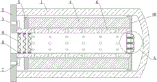
FIG. 1 is a schematic view of the overall structure of the present invention;
fig. 2 is a schematic structural diagram of a portion a of fig. 1 according to the present invention.
In the figure: 1-shell, 2-metal plate, 3-oil inlet, 4-filter paper, 5-guide ring, 6-central cylinder, 7-check valve, 8-filter element frame, 9-filter element screen plate, 10-baffle frame, 11-sealing ring, 12-ventilation screen plate, 13-expansion spring, 14-expansion rod, 15-top plate and 16-bypass valve block.
Detailed Description
The technical solutions in the embodiments of the present invention will be described clearly and completely with reference to the accompanying drawings in the embodiments of the present invention, and it is obvious that the described embodiments are only some embodiments of the present invention, not all embodiments. Based on the embodiments in the present invention, all other embodiments obtained by a person skilled in the art without creative work belong to the protection scope of the present invention.
Referring to fig. 1-2, the present invention provides a technical solution:
an oil filter with a multi-filter element and a multi-bypass valve comprises a shell 1 and a metal plate 2, wherein the metal plate 2 is fixedly connected to the left end face of the shell 1, an oil inlet 3 which is distributed up and down is formed in the left end face of the metal plate 2, filter paper 4 is arranged in the shell 1, a central cylinder 6 is arranged in the filter paper 4, a flow guide ring 5 is fixedly connected to the outer side of the left end of the central cylinder 6, the flow guide ring 5 is arranged to ensure the normal flow of oil, check valves 7 which are distributed up and down are arranged on the left side of the flow guide ring 5, the check valves 7 are arranged to prevent the backflow of oil, the outer sides of the check valves 7 are fixedly connected with the central cylinder 6, a baffle frame 10 is arranged on the right side of the central cylinder 6, a sealing ring 11 is fixedly connected to the left end face of the baffle frame 10, the sealing ring 11 is arranged to prevent the oil from passing through, the, telescopic link 14 outside all is equipped with expanding spring 13, the equal fixedly connected with roof 15 of 14 right-hand members of telescopic link, the equal fixedly connected with bypass valve block 16 of roof 15 right-hand member face.
The right end face of the blocking frame 10 is convexly arranged, the right end face of the blocking frame 10 is provided with uniformly distributed through holes, the right end face of the bypass valve block 16 is arranged in an arc shape, the arrangement ensures that the bypass valve block moves leftwards to compress the telescopic spring 13 when being stressed, the outer side of the bypass valve block 16 is in sliding connection with the blocking frame 10 through the through holes, the area of the right end face of the top plate 15 is 1.3 times of that of the right end face of the through holes, the arrangement of the top plate 15 prevents the bypass valve block 16 from excessively sliding rightwards, the left end face of the telescopic spring 13 is fixedly connected with the vent screen plate 12, the right end face of the telescopic spring 13 is fixedly connected with the top plate 15, the outer side of the vent screen plate 12 is provided with uniformly distributed vent holes, the arrangement ensures the normal circulation of oil, the sealing ring 11 is arranged in a cylindrical shape, the outer side of the sealing ring 11 is in a sealing, the inside equal fixedly connected with filter core otter board 9 of filter core frame 8, filter core otter board 9 all are pincher trees setting, and filter core otter board 9 large tracts of land and oil contact to realize quick filter effect, filter core frame 8 are the annular setting, and this kind of setting is guaranteed that oil can obtain filtering through filter core otter board 9.
The working process is as follows: when the oil filter is used, oil enters through the oil inlet 3, the check valve 7 is opened at the moment, the oil passes through the outer side of the flow guide ring 5 and then enters the inner part of the filter paper 4 and the central cylinder 6, the filter paper 4 plays a role in filtering, at the moment, the equipment normally operates, when the filter paper 4 is seriously blocked under special conditions, the oil enters the right side of the equipment through the outer side of the baffle frame 10, then when the pressure is at a certain value, the bypass valve block 16 is extruded, the bypass valve block 16 extrudes the telescopic rod 14 and the telescopic spring 13, so that the oil is normally conveyed into the inner part of the central cylinder 6 through the ventilating screen plate 12, the arrangement ensures that a single bypass valve cannot operate when being damaged, and can also ensure the normal supply of the oil, the oil can be sufficiently conveyed through the plurality of the bypass valves, when the oil passes through the filter element screen plate 9, impurities in the, has good use effect.
Although embodiments of the present invention have been shown and described, it will be appreciated by those skilled in the art that changes, modifications, substitutions and alterations can be made in these embodiments without departing from the principles and spirit of the invention, the scope of which is defined in the appended claims and their equivalents.
Claims (5)
1. The utility model provides an oil cleaner with many bypass valves of multi-filter core, includes casing (1) and metal sheet (2), its characterized in that: the oil filter is characterized in that a metal plate (2) is fixedly connected to the left end face of the shell (1), an oil inlet (3) which is vertically distributed is formed in the left end face of the metal plate (2), filter paper (4) is arranged inside the shell (1), a central cylinder (6) is arranged inside the filter paper (4), a flow guide ring (5) is fixedly connected to the outer side of the left end of the central cylinder (6), check valves (7) which are vertically distributed are arranged on the left side of the flow guide ring (5), the outer sides of the check valves (7) are fixedly connected with the central cylinder (6), a blocking frame (10) is arranged on the right side of the central cylinder (6), a sealing ring (11) is fixedly connected to the left end face of the blocking frame (10), an air vent screen plate (12) is fixedly connected to the left end face of the sealing ring (11), telescopic rods (14) which are uniformly distributed are fixedly connected to, the telescopic link (14) equal fixedly connected with roof (15) of right-hand member face, the equal fixedly connected with bypass valve block (16) of roof (15) right-hand member face.
2. An oil filter provided with a multi-cartridge multi-bypass valve according to claim 1 wherein: keep off frame (10) right-hand member and personally submit protruding setting, keep off frame (10) right-hand member face and set up evenly distributed's through-hole, bypass valve piece (16) right-hand member personally submits the arc setting, bypass valve piece (16) outside is through-hole and fender frame (10) sliding connection, roof (15) right-hand member face area is 1.3 times of through-hole right-hand member face area.
3. An oil filter provided with a multi-cartridge multi-bypass valve according to claim 1 wherein: the left end face of each telescopic spring (13) is fixedly connected with the corresponding ventilating screen plate (12), the right end face of each telescopic spring (13) is fixedly connected with the corresponding top plate (15), and the outer side of each ventilating screen plate (12) is provided with uniformly distributed air holes.
4. An oil filter provided with a multi-cartridge multi-bypass valve according to claim 1 wherein: the sealing ring (11) is arranged in a cylindrical shape, and the outer side of the sealing ring (11) is arranged in a sealing manner with the inner wall of the central cylinder (6).
5. An oil filter provided with a multi-cartridge multi-bypass valve according to claim 1 wherein: the filter element comprises a central cylinder (6), wherein a filter element frame (8) is fixedly connected with the left side and evenly distributed inside the central cylinder, a filter element screen plate (9) is fixedly connected with the inside of the filter element frame (8), the filter element screen plate (9) is arranged in a folded mode, and the filter element frame (8) is arranged in an annular mode.
Priority Applications (1)
| Application Number | Priority Date | Filing Date | Title |
|---|---|---|---|
| CN202021429218.6U CN212803359U (en) | 2020-07-20 | 2020-07-20 | Oil cleaner with many filter cores bypass valve |
Applications Claiming Priority (1)
| Application Number | Priority Date | Filing Date | Title |
|---|---|---|---|
| CN202021429218.6U CN212803359U (en) | 2020-07-20 | 2020-07-20 | Oil cleaner with many filter cores bypass valve |
Publications (1)
| Publication Number | Publication Date |
|---|---|
| CN212803359U true CN212803359U (en) | 2021-03-26 |
Family
ID=75103446
Family Applications (1)
| Application Number | Title | Priority Date | Filing Date |
|---|---|---|---|
| CN202021429218.6U Expired - Fee Related CN212803359U (en) | 2020-07-20 | 2020-07-20 | Oil cleaner with many filter cores bypass valve |
Country Status (1)
| Country | Link |
|---|---|
| CN (1) | CN212803359U (en) |
Cited By (1)
| Publication number | Priority date | Publication date | Assignee | Title |
|---|---|---|---|---|
| CN114893275A (en) * | 2022-05-18 | 2022-08-12 | 安徽安凯汽车股份有限公司 | Oil cleaner and maintenance device with many filter cores and bypass valves |
-
2020
- 2020-07-20 CN CN202021429218.6U patent/CN212803359U/en not_active Expired - Fee Related
Cited By (1)
| Publication number | Priority date | Publication date | Assignee | Title |
|---|---|---|---|---|
| CN114893275A (en) * | 2022-05-18 | 2022-08-12 | 安徽安凯汽车股份有限公司 | Oil cleaner and maintenance device with many filter cores and bypass valves |
Similar Documents
| Publication | Publication Date | Title |
|---|---|---|
| CN109569111A (en) | A kind of filter device handling coating cloud exhaust gas | |
| CN216688438U (en) | A cross air blast apparatus for chemical fibre spinning | |
| CN208436564U (en) | A kind of twin flue formula air cleaning filter | |
| CN219518272U (en) | Oil mist collecting device | |
| CN217015117U (en) | Filter absorber | |
| CN217773397U (en) | Special high efficiency filtration equipment of high performance printing ink | |
| CN213063703U (en) | Oil filter | |
| CN215388320U (en) | Air filtering device for spinning workshop | |
| CN214273759U (en) | Filter mesh type oil suction pipe and engine | |
| CN212701002U (en) | Exhaust-gas treatment is with discharging pipeline | |
| CN210159367U (en) | Natural gas filtration equipment | |
| CN212454753U (en) | Special air compressor for laser cutting machine | |
| CN213492616U (en) | Air filter element capable of reducing flow resistance | |
| CN211935973U (en) | double-V-shaped oil removal pre-filtering mechanism | |
| CN209138172U (en) | A kind of steam turbine valve strainer | |
| CN214836615U (en) | High-efficiency oil filter convenient to disassemble and assemble | |
| CN218821705U (en) | Sintering furnace dust removal filter equipment | |
| CN220715051U (en) | Filter convenient to change filter screen | |
| CN209662865U (en) | A kind of plasma photodissociation all-in-one machine mediated convenient for exhaust gas | |
| CN218553493U (en) | Filter box device with drying section for reducing particulate matters and sundries | |
| CN221683160U (en) | An air filter element device used in air compressor | |
| CN219897473U (en) | High-efficiency filtering system for refined sulfuric acid furnace gas | |
| CN223042353U (en) | A high efficiency air filter structure | |
| CN212719889U (en) | Front-mounted filtering range hood | |
| CN219662534U (en) | Exhaust emission structure of anesthesia machine |
Legal Events
| Date | Code | Title | Description |
|---|---|---|---|
| GR01 | Patent grant | ||
| GR01 | Patent grant | ||
| CF01 | Termination of patent right due to non-payment of annual fee |
Granted publication date: 20210326 |
|
| CF01 | Termination of patent right due to non-payment of annual fee |