CN212795748U - Pouring gate structure of injection mold - Google Patents
Pouring gate structure of injection mold Download PDFInfo
- Publication number
- CN212795748U CN212795748U CN202021328286.3U CN202021328286U CN212795748U CN 212795748 U CN212795748 U CN 212795748U CN 202021328286 U CN202021328286 U CN 202021328286U CN 212795748 U CN212795748 U CN 212795748U
- Authority
- CN
- China
- Prior art keywords
- runner
- injection mold
- worm
- inlet tube
- cooling water
- Prior art date
- Legal status (The legal status is an assumption and is not a legal conclusion. Google has not performed a legal analysis and makes no representation as to the accuracy of the status listed.)
- Expired - Fee Related
Links
- 238000002347 injection Methods 0.000 title claims abstract description 17
- 239000007924 injection Substances 0.000 title claims abstract description 17
- 239000000498 cooling water Substances 0.000 claims abstract description 19
- XLYOFNOQVPJJNP-UHFFFAOYSA-N water Substances O XLYOFNOQVPJJNP-UHFFFAOYSA-N 0.000 claims abstract description 7
- 230000007246 mechanism Effects 0.000 claims description 12
- 238000005491 wire drawing Methods 0.000 abstract description 9
- 239000002826 coolant Substances 0.000 abstract description 6
- 239000007788 liquid Substances 0.000 abstract description 6
- 239000000463 material Substances 0.000 abstract description 6
- 238000000465 moulding Methods 0.000 abstract description 6
- 238000001816 cooling Methods 0.000 abstract description 4
- 239000004033 plastic Substances 0.000 abstract description 4
- 229920003023 plastic Polymers 0.000 abstract description 4
- 230000002349 favourable effect Effects 0.000 abstract description 3
- 238000004519 manufacturing process Methods 0.000 abstract description 3
- 239000007858 starting material Substances 0.000 abstract description 3
- 238000001746 injection moulding Methods 0.000 description 4
- FGRBYDKOBBBPOI-UHFFFAOYSA-N 10,10-dioxo-2-[4-(N-phenylanilino)phenyl]thioxanthen-9-one Chemical compound O=C1c2ccccc2S(=O)(=O)c2ccc(cc12)-c1ccc(cc1)N(c1ccccc1)c1ccccc1 FGRBYDKOBBBPOI-UHFFFAOYSA-N 0.000 description 1
- 230000004075 alteration Effects 0.000 description 1
- 230000009286 beneficial effect Effects 0.000 description 1
- 239000003086 colorant Substances 0.000 description 1
- 239000000110 cooling liquid Substances 0.000 description 1
- 235000019628 coolness Nutrition 0.000 description 1
- 238000010586 diagram Methods 0.000 description 1
- 230000006872 improvement Effects 0.000 description 1
- 238000000034 method Methods 0.000 description 1
- 230000004048 modification Effects 0.000 description 1
- 238000012986 modification Methods 0.000 description 1
- 239000000243 solution Substances 0.000 description 1
- 238000006467 substitution reaction Methods 0.000 description 1
Images


Landscapes
- Moulds For Moulding Plastics Or The Like (AREA)
Abstract
The utility model relates to an injection mold technical field just discloses an injection mold's mouth of watering structure, which comprises a die, the mould top sets up the feed inlet, inside runner and the cooling water course of being provided with of mould, runner and feed inlet intercommunication, the runner is close to feed inlet department lateral wall and has seted up the trompil, the cooling water course distributes in the runner both sides, the water inlet department fixedly connected with inlet tube of cooling water course. This injection mold's pouring gate mouth structure, starter motor when material is got to the end of moulding plastics, can drive worm and threaded rod and rotate, the worm rotates drive driving valve rod and the butterfly plate rotation of accessible worm wheel, open the inlet tube, make the coolant liquid enter into the cooling water course, so can accelerate the cooling of runner department product, be favorable to reducing the probability that wire drawing phenomenon appears, the threaded rod rotates simultaneously and can make flashboard lateral shifting plug up the runner top, further reduce wire drawing phenomenon, thereby avoid influencing product production quality.
Description
Technical Field
The utility model relates to an injection mold technical field specifically is an injection mold's mouthful structure of watering.
Background
The injection molding is a molding method combining injection molding and molding, and is characterized by high production speed, high efficiency, automatic operation, various colors, shapes from simple to complex, sizes from large to small, accurate product size, easy product replacement and capability of molding products with complex shapes. The main principle is that plastic material which is completely melted is stirred by a screw at a certain temperature, injected into a mold cavity by high pressure, and cooled and solidified to obtain a molded product.
The existing injection molding part is easy to generate wire drawing phenomenon when taking materials, influences the product quality and needs further improvement.
SUMMERY OF THE UTILITY MODEL
Technical problem to be solved
Not enough to prior art, the utility model provides an injection mold's mouth of watering structure possesses advantages such as can improve the wire drawing phenomenon, has solved present injection molding and has easily produced the wire drawing phenomenon when getting the material, influences product quality, needs further modified problem.
(II) technical scheme
In order to achieve the above object, the utility model provides a following technical scheme: the utility model provides an injection mold's mouth of watering structure, includes the mould, the mould top sets up the feed inlet, inside runner and the cooling water course of being provided with of mould, runner and feed inlet intercommunication, the runner is close to feed inlet department lateral wall and has seted up the trompil, the cooling water course distributes in the runner both sides, the fixedly connected with inlet tube of the inlet department of cooling water course, inlet tube top fixedly connected with motor, the fixed first shut-off mechanism that is provided with on the motor output shaft, be provided with second shut-off mechanism on the inlet tube.
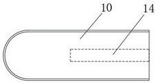
Preferably, first shut off mechanism includes the worm, worm one end and motor output shaft fixed connection, worm other end fixedly connected with threaded rod, threaded rod one end extends to inside the trompil, the threaded rod is located the inside one end of trompil and is equipped with the flashboard, the threaded hole is seted up to the flashboard side, the flashboard passes through screw hole and threaded rod threaded connection.
Preferably, the second brake-off mechanism includes the valve rod, fixedly connected with butterfly plate on the valve rod, diapire swing joint in valve rod bottom and the inlet tube, roof swing joint in valve rod top and the inlet tube, the valve rod top runs through the inlet tube in the roof and extends to the inlet tube top valve rod top fixedly connected with worm wheel, worm wheel and worm mesh.
Preferably, the cross-sectional shape of the gate matches the cross-sectional shape of the opening, and one end of the gate extends to the side wall of the gate.
Preferably, the gate is provided in a conical shape, and the taper of the gate is provided at-degree.
Compared with the prior art, the utility model provides an injection mold's mouthful structure of watering possesses following beneficial effect:
this injection mold's pouring gate mouth structure, the starter motor when material is got to the end of moulding plastics, the motor can drive worm and threaded rod and rotate, the worm rotates drive movable valve rod and the butterfly plate rotation of accessible worm wheel, open the inlet tube, make the coolant liquid enter into the cooling water course, with this cooling that can accelerate runner department product, be favorable to reducing the probability that wire drawing phenomenon appears, the threaded rod rotates simultaneously and can make flashboard lateral shifting plug up the runner top, further reduce wire drawing phenomenon, thereby avoid influencing product production quality.
Drawings
Fig. 1 is a schematic view of the overall structure of the present invention;
FIG. 2 is an enlarged view of the portion A of FIG. 1 according to the present invention;
fig. 3 is a schematic structural diagram of the valve rod of the present invention.
Wherein: 1. a mold; 2. a feed inlet; 3. a gate; 4. a cooling water channel; 5. opening a hole; 6. a water inlet pipe; 7. a motor; 8. a worm; 9. a threaded rod; 10. a shutter plate; 11. a valve stem; 12. a butterfly plate; 13. a worm gear; 14. a threaded bore.
Detailed Description
The technical solutions in the embodiments of the present invention will be described clearly and completely with reference to the accompanying drawings in the embodiments of the present invention, and it is obvious that the described embodiments are only some embodiments of the present invention, not all embodiments. Based on the embodiments in the present invention, all other embodiments obtained by a person skilled in the art without creative work belong to the protection scope of the present invention.
Referring to fig. 1-3, a sprue gate structure of an injection mold comprises a mold 1, a feed inlet 2 is arranged at the top of the mold 1, the feed inlet 2 is provided with a cambered groove, a sprue 3 and a cooling water channel 4 are arranged inside the mold 1, the cooling water channel 4 is formed by a plurality of straight water channels which are communicated with each other and surround the sprue 3, cooling liquid is filled inside the cooling water channel 4 in an initial state, the sprue 3 is communicated with the feed inlet 2, the top end of the sprue 3 is communicated with the bottom of the cambered groove, the sprue 3 is conical, the taper of the sprue 3 is set to be 2-6 degrees, an opening 5 is formed in the side wall of the sprue 3 close to the feed inlet 2, the cooling water channels 4 are distributed at two sides of the sprue 3, a water inlet 6 is fixedly connected to the water inlet of the cooling water channel 4, the water inlet 6 is horizontally arranged, in practical, a first brake-off mechanism is fixedly arranged on an output shaft of the motor 7, and a second brake-off mechanism is arranged on the water inlet pipe 6.
First shut-off mechanism includes worm 8, 8 one end of worm and 7 output shaft fixed connection of motor, 8 other end fixedly connected with threaded rod 9 of worm, 9 one end of threaded rod extends to inside 5 trompils, threaded rod 9 is located the inside one end of 5 trompils and is equipped with flashboard 10, flashboard 10 side set up threaded hole 14, flashboard 10 passes through threaded hole 14 and 9 threaded connection of threaded rod, the cross sectional shape of flashboard 10 cross sectional shape and trompil 5 matches, 10 one end of flashboard extends to 3 lateral walls in runner, flashboard 10 is located 3 lateral walls one end in runner and is provided with the arc limit, be favorable to rotating through threaded rod 9 and can drive flashboard 10 lateral shifting in trompil 5, and then 3 gates in the runner.
Second shut-off mechanism includes valve rod 11, fixedly connected with butterfly plate 12 on the valve rod 11, wall swing joint in 11 bottoms of valve rod and the inlet tube 6, roof swing joint in 11 tops of valve rod runs through the inlet tube 6 and extends to the 11 top fixedly connected with worm wheel 13 of the valve rod top of inlet tube 6, valve rod 11 is sealed the setting with inlet tube 6 junction, worm wheel 13 and the meshing of worm 8, it can drive worm wheel 13 through the rotation of worm 8, and then make 11 and the rotation of butterfly plate 12 of valve rod, inlet tube 6 can be opened with this, make the coolant liquid get into cooling water course 4, the flow of coolant liquid can be fast to runner 3 coolings with higher speed.
When using, the completion of moulding plastics is at starter motor 7 when getting the material, motor 7 operation can drive screw rod and threaded rod 9 on the output shaft and rotate, worm 8 rotates and can drive worm wheel 13 and valve rod 11 and rotate, and then drive butterfly plate 12 and rotate, can make the coolant liquid get into cooling water channel 4, the coolant liquid flow with higher speed, realize the quick cooling to runner 3, avoid the wire drawing phenomenon with this, meanwhile, threaded rod 9 can drive flashboard 10 when rotating and remove to 3 one side in 5 inside to the runner of trompil, can be close to feed inlet 2 play with runner 3 and plug up, the wire drawing phenomenon has further been avoided.
Although embodiments of the present invention have been shown and described, it will be appreciated by those skilled in the art that changes, modifications, substitutions and alterations can be made in these embodiments without departing from the principles and spirit of the invention, the scope of which is defined in the appended claims and their equivalents.
Claims (5)
1. The utility model provides an injection mold's runner mouth structure, includes mould (1), its characterized in that: mould (1) top sets up feed inlet (2), mould (1) is inside to be provided with runner (3) and cooling water course (4), runner (3) and feed inlet (2) intercommunication, runner (3) are close to feed inlet (2) and locate the lateral wall and seted up trompil (5), cooling water course (4) distribute in runner (3) both sides, the water inlet fixedly connected with inlet tube (6) of cooling water course (4), inlet tube (6) top fixedly connected with motor (7), the fixed first shut-off mechanism that is provided with on motor (7) output shaft, be provided with the second shut-off mechanism on inlet tube (6).
2. The sprue structure of an injection mold according to claim 1, wherein: first floodgate disconnected mechanism includes worm (8), worm (8) one end and motor (7) output shaft fixed connection, worm (8) other end fixedly connected with threaded rod (9), threaded rod (9) one end extends to trompil (5) inside, threaded rod (9) are located inside one end of trompil (5) and are equipped with flashboard (10), threaded hole (14) are seted up to flashboard (10) side, flashboard (10) are through threaded hole (14) and threaded rod (9) threaded connection.
3. The sprue structure of an injection mold according to claim 2, wherein: second floodgate disconnected mechanism includes valve rod (11), fixedly connected with butterfly plate (12) on valve rod (11), wall swing joint in valve rod (11) bottom and inlet tube (6), roof swing joint in valve rod (11) top and inlet tube (6), roof and extension to inlet tube (6) top in inlet tube (6) are run through on valve rod (11) top fixedly connected with worm wheel (13), worm wheel (13) and worm (8) meshing.
4. The sprue structure of an injection mold according to claim 2, wherein: the cross-sectional shape of the gate plate (10) is matched with that of the opening (5), and one end of the gate plate (10) extends to the side wall of the pouring gate (3).
5. The sprue structure of an injection mold according to claim 1, wherein: the sprue (3) is conical, and the taper of the sprue (3) is 2-6 degrees.
Priority Applications (1)
| Application Number | Priority Date | Filing Date | Title |
|---|---|---|---|
| CN202021328286.3U CN212795748U (en) | 2020-07-08 | 2020-07-08 | Pouring gate structure of injection mold |
Applications Claiming Priority (1)
| Application Number | Priority Date | Filing Date | Title |
|---|---|---|---|
| CN202021328286.3U CN212795748U (en) | 2020-07-08 | 2020-07-08 | Pouring gate structure of injection mold |
Publications (1)
| Publication Number | Publication Date |
|---|---|
| CN212795748U true CN212795748U (en) | 2021-03-26 |
Family
ID=75100053
Family Applications (1)
| Application Number | Title | Priority Date | Filing Date |
|---|---|---|---|
| CN202021328286.3U Expired - Fee Related CN212795748U (en) | 2020-07-08 | 2020-07-08 | Pouring gate structure of injection mold |
Country Status (1)
| Country | Link |
|---|---|
| CN (1) | CN212795748U (en) |
-
2020
- 2020-07-08 CN CN202021328286.3U patent/CN212795748U/en not_active Expired - Fee Related
Similar Documents
| Publication | Publication Date | Title |
|---|---|---|
| CN106738659A (en) | Rotation is de- to move back mold mechanism and injection machine | |
| CN202985970U (en) | Injection mold with ox horn runner | |
| CN117621372A (en) | Automatic cutting glue feeding mechanism of injection mold | |
| CN107297849B (en) | Turnover open-close type rapid forming die | |
| CN215703595U (en) | Demoulding device for plastic mould | |
| CN202114867U (en) | Injection mold with insert | |
| CN211307193U (en) | A precision mold for forming plastic products | |
| CN212764494U (en) | Precision mold of electric vehicle storage battery injection molding piece | |
| CN210477634U (en) | A two-color plastic mold | |
| CN206383416U (en) | Rotation is de- to move back mold mechanism and injection machine | |
| CN217123865U (en) | Automatic shearing device for water gap | |
| CN213500437U (en) | Injection molding machine injection molding device | |
| CN215283228U (en) | Multi-station extrusion molding integrated machine | |
| CN217073203U (en) | Plastic mould with optimized runner structure | |
| CN210880668U (en) | Water-cooling sprue bush | |
| CN210758935U (en) | An earphone injection mold | |
| CN207128198U (en) | Wiring sheath hot runner mould | |
| CN203765952U (en) | Toothed mould | |
| CN216182339U (en) | Continuous injection mold | |
| CN112078097A (en) | Embedded type unsupported full-encapsulation injection molding process | |
| CN207747350U (en) | A kind of lamp holder mold | |
| CN222858638U (en) | A gate structure of a runnerless injection mold | |
| CN221089791U (en) | Plastic kettle mold with cap thread spiral demoulding mechanism | |
| CN208962266U (en) | A new type of plastic mold | |
| CN222271111U (en) | Hot runner flow distribution plate for injection molding |
Legal Events
| Date | Code | Title | Description |
|---|---|---|---|
| GR01 | Patent grant | ||
| GR01 | Patent grant | ||
| CF01 | Termination of patent right due to non-payment of annual fee | ||
| CF01 | Termination of patent right due to non-payment of annual fee |
Granted publication date: 20210326 |