CN212786621U - Agricultural machine fertilizer injection unit - Google Patents

Agricultural machine fertilizer injection unit Download PDF

Info

Publication number
CN212786621U
CN212786621U CN202021865523.XU CN202021865523U CN212786621U CN 212786621 U CN212786621 U CN 212786621U CN 202021865523 U CN202021865523 U CN 202021865523U CN 212786621 U CN212786621 U CN 212786621U
Authority
CN
China
Prior art keywords
cover plate
pull rod
plate
drum
agricultural machinery
Prior art date
Legal status (The legal status is an assumption and is not a legal conclusion. Google has not performed a legal analysis and makes no representation as to the accuracy of the status listed.)
Expired - Fee Related
Application number
CN202021865523.XU
Other languages
Chinese (zh)
Inventor
钟林平
张永鑫
Current Assignee (The listed assignees may be inaccurate. Google has not performed a legal analysis and makes no representation or warranty as to the accuracy of the list.)
Wenzhou Polytechnic
Original Assignee
Wenzhou Polytechnic
Priority date (The priority date is an assumption and is not a legal conclusion. Google has not performed a legal analysis and makes no representation as to the accuracy of the date listed.)
Filing date
Publication date
Application filed by Wenzhou Polytechnic filed Critical Wenzhou Polytechnic
Priority to CN202021865523.XU priority Critical patent/CN212786621U/en
Application granted granted Critical
Publication of CN212786621U publication Critical patent/CN212786621U/en
Expired - Fee Related legal-status Critical Current
Anticipated expiration legal-status Critical

Links

Images

Landscapes

  • Fertilizing (AREA)

Abstract

本实用新型涉及农业机械技术领域,且公开了一种农业机械施肥装置,包括底架、支撑柱、料仓、第一盖板、第二盖板、传动装置,所述传动装置连接转动轴和搅拌叶片,所述料仓底部固定设置有出料口和挡料板,所述挡料板两端连接设置有开关装置、拉绳和拉杆,所述底架一端固定设置有推拉杆,所述推拉杆一侧外壁固定设置有限位环和拉杆套管,所述底架下部两端设置有第一转筒和第二转筒,所述第一转筒和第二转筒连接设置有链板,所述链板表面固定设置有挡板。该农业机械施肥装置,通过设置螺旋状搅拌叶片,使得肥料可以充分搅拌后再进行施肥,通过设置拉杆、拉绳和开关装置,使得可以控制挡料板的拉伸,从而控制出料口的流量。

Figure 202021865523

The utility model relates to the technical field of agricultural machinery, and discloses a fertilization device for agricultural machinery, which comprises a bottom frame, a support column, a silo, a first cover plate, a second cover plate and a transmission device, wherein the transmission device is connected with a rotating shaft and A stirring blade, a discharge port and a baffle plate are fixed at the bottom of the silo, a switch device, a pull rope and a pull rod are connected at both ends of the baffle plate, and a push-pull rod is fixed at one end of the chassis. The outer wall of one side of the push-pull rod is fixedly provided with a limiting ring and a pull-rod sleeve, the lower ends of the bottom frame are provided with a first drum and a second drum, and the first drum and the second drum are connected with a chain plate. , a baffle plate is fixed on the surface of the chain plate. The agricultural machinery fertilization device is equipped with a spiral stirring blade, so that the fertilizer can be fully stirred before fertilizing. By setting a pull rod, a pull rope and a switch device, the stretch of the baffle plate can be controlled, thereby controlling the flow rate of the discharge port. .

Figure 202021865523

Description

Agricultural machine fertilizer injection unit
Technical Field
The utility model relates to the technical field of agricultural machinery, specifically be an agricultural machinery fertilizer injection unit.
Background
Agricultural machinery refers to various machines used in the production process of crop planting and animal husbandry, as well as in the primary processing and treatment process of agricultural and animal products. Agricultural machinery includes agricultural power machinery, farmland construction machinery, soil farming machinery, planting and fertilizing machinery, plant protection machinery, farmland irrigation and drainage machinery, crop harvesting machinery, agricultural product processing machinery, animal husbandry machinery, agricultural transportation machinery and the like.
Fertilization refers to an agricultural technical measure of applying a fertilizer into soil or spraying the fertilizer on plants, providing nutrients required by the plants and maintaining and improving the soil fertility. With the rapid development of economy and science and technology in China in recent years, the science and technology level in China has been remarkably developed, and the traditional manual fertilization is gradually changed into mechanical fertilization.
However, the mixing effect of the agricultural fertilizing device in the prior art is still to be improved, and the mixing is not uniform; meanwhile, the flow of the fertilizer is not convenient to control when the fertilizer is spread, and the fertilizer is easy to waste.
Disclosure of Invention
Technical problem to be solved
Not enough to prior art, the utility model provides an agricultural machine fertilizer injection unit possesses the control and scatters advantages such as flow, saving fertilizer, has solved the problem that proposes in the above-mentioned background art.
(II) technical scheme
In order to achieve the above object, the utility model provides a following technical scheme: an agricultural machinery fertilizing device comprises an underframe, wherein a supporting column is fixedly arranged on the upper portion of the underframe, a storage bin is fixedly arranged on the upper portion of the supporting column, a first cover plate and a second cover plate are arranged on the top of the storage bin, a handle is fixedly arranged on the upper portion of the second cover plate, the first cover plate and the second cover plate are hinged through a hinge, a transmission device is arranged on the upper portion of the first cover plate, one end of a belt is connected and arranged at the output shaft end of the transmission device, the other end of the belt is connected and arranged with a rotating shaft, a stirring blade is fixedly arranged in the middle of the rotating shaft, a discharge port is fixedly arranged at the bottom of the storage bin, a striker plate is arranged on one side of the discharge port in a long hole mode, two ends of the striker plate are connected and provided, the pull rod is fixedly arranged at one end of the bottom frame, a limiting ring is fixedly arranged on the outer wall of one side of the pull rod, a pull rod sleeve is fixedly arranged on the outer wall of one side of the upper portion inside the pull rod, the pull rod is arranged in the pull rod sleeve in a nested mode, the pull rod is connected with the other end of the pull rope, a first rotary drum and a second rotary drum are arranged at two ends of the lower portion of the bottom frame, chain plates are arranged on the first rotary drum and the second rotary drum in a connected mode, and baffles are fixedly.
Preferably, the upper part of the storage bin is rectangular, the lower part of the storage bin is conical, and the discharge hole is fixed at the bottom of the conical part.
Preferably, the first cover plate and the second cover plate are connected into a whole through a hinge, the first cover plate is fixed at the top of the storage bin, and the second cover plate can rotate by taking the hinge as an axis.
Preferably, stirring vane is the heliciform, sets up in the inside middle part of feed bin and connects in the axis of rotation outer wall, and feed bin one side is extended to axis of rotation one end.
Preferably, one end of the pull rope is connected with the pull ring, the middle part of the pull rope penetrates through the limiting ring, and the other end of the pull rope is connected with the pull rod.
Preferably, the chain plate is connected around the outer walls of the first rotating drum and the second rotating drum, and a plurality of baffle plates are uniformly arranged on the surface of the chain plate.
Compared with the prior art, the utility model provides an agricultural machine fertilizer injection unit possesses following beneficial effect: this agricultural machine fertilizer injection unit through setting up heliciform stirring vane for fertilize again after fertilizer can the intensive mixing, through setting up pull rod, stay cord and switching device, make the drawing that can control the striker plate, thereby the flow of control discharge gate.
Drawings
FIG. 1 is a side sectional view of the structure of the present invention;
FIG. 2 is a perspective view of the present invention;
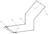
fig. 3 is a schematic view of the striker plate control device of the present invention;
fig. 4 is a schematic structural diagram of the switching device of the present invention.
Wherein: 1. a chassis; 2. a support pillar; 3. a storage bin; 4. a first cover plate; 5. a second cover plate; 6. a handle; 7. a hinge; 8. a transmission device; 9. a stirring blade; 10. a belt; 11. a discharge port; 12. a rotating shaft; 13. a striker plate; 14. a switching device; 1401. fixing the rod; 1402. a fixing plate; 1403. a spring; 1404. fixing a nut; 1405. a pull ring; 15. a push-pull rod; 16. a limiting ring; 17. a pull rod; 18. a pull rod sleeve; 19. a first rotating drum; 20. a second rotating drum; 21. a chain plate; 22. a baffle plate; 23. and pulling a rope.
Detailed Description
The technical solutions in the embodiments of the present invention will be described clearly and completely with reference to the accompanying drawings in the embodiments of the present invention, and it is obvious that the described embodiments are only some embodiments of the present invention, not all embodiments. Based on the embodiments in the present invention, all other embodiments obtained by a person skilled in the art without creative work belong to the protection scope of the present invention.
Referring to fig. 1-4, an agricultural machinery fertilizing apparatus comprises an underframe 1, a supporting column 2 is fixedly arranged on the upper portion of the underframe 1, a bin 3 is fixedly arranged on the upper portion of the supporting column 2, the upper portion of the bin 3 is rectangular, the lower portion of the bin is conical, a discharge port 11 is fixed on the bottom of the conical, a first cover plate 4 and a second cover plate 5 are arranged on the top of the bin 3, a handle 6 is fixedly arranged on the upper portion of the second cover plate 5, the first cover plate 4 and the second cover plate 5 are hinged through a hinge 7, the first cover plate 4 and the second cover plate 5 are connected into a whole through the hinge 7, the first cover plate 4 is fixed on the top of the bin 3, the second cover plate 5 can rotate by taking the hinge 7 as an axis, a transmission device 8 is arranged on the upper portion of the first cover plate 4, one end of a belt 10 is connected to, the stirring blade 9 is in a spiral shape and is arranged in the middle of the interior of the bin 3 and connected to the outer wall of the rotating shaft 12, one end of the rotating shaft 12 extends out of one side of the bin 3, a discharge port 11 is fixedly arranged at the bottom of the bin 3, a striker plate 13 is arranged on one side of the discharge port 11 in a long hole installation manner, two ends of the striker plate 13 are connected with switch devices 14, each switch device 14 comprises a fixed rod 1401, a fixed plate 1402, a spring 1403, a fixed nut 1404 and a pull ring 1405, the tail end of each switch device 14 is connected with one end of a pull rope 23, one end of the underframe 1 is fixedly provided with a push-pull rod 15, the outer wall of one side of the push-pull rod 15 is fixedly provided with a limit ring 16, the outer wall of one side of the upper portion of the interior of the push-pull, a first rotating drum 19 and a second rotating drum 20 are arranged at two ends of the lower portion of the underframe 1, a chain plate 21 is arranged at the two ends of the lower portion of the underframe 19 in a connecting mode, a baffle plate 22 is fixedly arranged on the surface of the chain plate 21, the chain plate 21 is connected around the outer wall of the first rotating drum 19 and the outer wall of the second rotating drum 20, and a plurality of baffle plates 22 are uniformly arranged on the surface of the chain plate 21.
In use, the agricultural machinery fertilizing device loads fertilizer into the bin 3 by opening the second cover plate 5 through the handle 6, the rotating shaft 12 is driven to rotate through the transmission device 8 arranged on the first cover plate 4 through the belt 10, so that the stirring blades 9 rotate, thereby stirring the fertilizer, the fully stirred fertilizer slides to the discharge hole 11 through the conical slope, the pull rod 17 is pulled to drive the pull rope 23 to pull the switch device 14, so that the striker plate 13 is opened, and the fertilizer falls on the chain plate 21, the chain plate 21 rolls back and forth by pushing or pulling the push-pull rod 15 fixed at one end of the underframe 1, the baffle 22 drives the fertilizer to move, the fertilizer is scattered into the soil by the contact of the chain plate 21 and the baffle 22 with the soil, can control 11 fertilizer loads of discharge gate according to the pulling range of pushing speed through pull rod 17, can practice thrift fertilizer when even fertilizer is scattered.
Although embodiments of the present invention have been shown and described, it will be appreciated by those skilled in the art that changes, modifications, substitutions and alterations can be made in these embodiments without departing from the principles and spirit of the invention, the scope of which is defined in the appended claims and their equivalents.

Claims (6)

1.一种农业机械施肥装置,包括底架(1),其特征在于:所述底架(1)上部固定设置有支撑柱(2),所述支撑柱(2)上部固定设置有料仓(3),所述料仓(3)顶部设置有第一盖板(4)和第二盖板(5),所述第二盖板(5)上部固定设置有把手(6),所述第一盖板(4)和第二盖板(5)通过铰链(7)铰接,所述第一盖板(4)上部安装设置有传动装置(8),所述传动装置(8)输出轴端连接设置有皮带(10)一端,所述皮带(10)另一端连接设置有转动轴(12),所述转动轴(12)中部固定设置有搅拌叶片(9),所述料仓(3)底部固定设置有出料口(11),所述出料口(11)一侧开设长孔安装设置有挡料板(13),所述挡料板(13)两端连接设置有开关装置(14),所述开关装置(14)包括固定杆(1401)、固定板(1402)、弹簧(1403)、固定螺母(1404)和拉环(1405),所述开关装置(14)末端连接设置有拉绳(23)一端,所述底架(1)一端固定设置有推拉杆(15),所述推拉杆(15)一侧外壁固定设置有限位环(16),所述推拉杆(15)内部上部一侧外壁固定设置有拉杆套管(18),所述拉杆套管(18)嵌套设置有拉杆(17),所述拉杆(17)连接拉绳(23)另一端,所述底架(1)下部两端设置有第一转筒(19)和第二转筒(20),所述第一转筒(19)和第二转筒(20)连接设置有链板(21),所述链板(21)表面固定设置有挡板(22)。1. A fertilizing device for agricultural machinery, comprising an underframe (1), characterized in that: a support column (2) is fixedly arranged on the upper part of the underframe (1), and a silo ( 3) A first cover plate (4) and a second cover plate (5) are arranged on the top of the silo (3), and a handle (6) is fixedly arranged on the upper part of the second cover plate (5). A cover plate (4) and a second cover plate (5) are hinged by a hinge (7), a transmission device (8) is installed on the upper part of the first cover plate (4), and the transmission device (8) outputs the shaft end One end of a belt (10) is connected, the other end of the belt (10) is connected with a rotating shaft (12), and a stirring blade (9) is fixedly arranged in the middle of the rotating shaft (12). A discharge port (11) is fixedly arranged at the bottom, a long hole is opened on one side of the discharge port (11), a baffle plate (13) is installed, and a switch device (13) is connected at both ends of the baffle plate (13). 14), the switch device (14) includes a fixing rod (1401), a fixing plate (1402), a spring (1403), a fixing nut (1404) and a pull ring (1405), the switch device (14) is connected to the end There is one end of the pull rope (23), one end of the bottom frame (1) is fixedly provided with a push-pull rod (15), and a limit ring (16) is fixedly arranged on the outer wall of one side of the push-pull rod (15). ) inside the upper part of one side outer wall is fixedly provided with a pull rod sleeve (18), the pull rod sleeve (18) is nested with a pull rod (17), the pull rod (17) is connected to the other end of the pull rope (23), the pull rod (18) A first drum (19) and a second drum (20) are provided at both ends of the lower part of the chassis (1), and chain plates (21) are connected to the first drum (19) and the second drum (20). ), a baffle plate (22) is fixed on the surface of the chain plate (21). 2.根据权利要求1所述的一种农业机械施肥装置,其特征在于:所述料仓(3)上部为矩形,下部为锥形,出料口(11)固定于锥形底部。2 . The agricultural machinery fertilizing device according to claim 1 , wherein the upper part of the silo ( 3 ) is rectangular, the lower part is conical, and the discharge port ( 11 ) is fixed at the bottom of the cone. 3 . 3.根据权利要求1所述的一种农业机械施肥装置,其特征在于:所述第一盖板(4)和第二盖板(5)通过铰链(7)连接为一个整体,第一盖板(4)固定于料仓(3)顶部,第二盖板(5)可以铰链(7)为轴心旋转。3. A fertilizing device for agricultural machinery according to claim 1, characterized in that: the first cover plate (4) and the second cover plate (5) are connected as a whole by a hinge (7), the first cover The plate (4) is fixed on the top of the silo (3), and the second cover plate (5) can be rotated by the hinge (7) as the axis. 4.根据权利要求1所述的一种农业机械施肥装置,其特征在于:所述搅拌叶片(9)呈螺旋状,设置于料仓(3)内部中部连接于转动轴(12)外壁,转动轴(12)一端延伸出料仓(3)一侧。4. An agricultural machinery fertilizing device according to claim 1, characterized in that: the stirring blade (9) is in a spiral shape, and is arranged in the inner middle of the silo (3) and is connected to the outer wall of the rotating shaft (12), and rotates One end of the shaft (12) extends out of the side of the material bin (3). 5.根据权利要求1所述的一种农业机械施肥装置,其特征在于:所述拉绳(23)一端连接于拉环(1405),中部贯穿限位环(16),另一端连接于拉杆(17)。5 . The agricultural machinery fertilizing device according to claim 1 , wherein one end of the pulling rope ( 23 ) is connected to the pulling ring ( 1405 ), the middle part runs through the limit ring ( 16 ), and the other end is connected to the pulling rod. 6 . (17). 6.根据权利要求1所述的一种农业机械施肥装置,其特征在于:所述链板(21)环绕第一转筒(19)和第二转筒(20)外壁连接,表面均匀设置有多个挡板(22)。6. A fertilizing device for agricultural machinery according to claim 1, characterized in that: the chain plate (21) is connected around the outer walls of the first drum (19) and the second drum (20), and the surface is evenly provided with A plurality of baffles (22).
CN202021865523.XU 2020-09-01 2020-09-01 Agricultural machine fertilizer injection unit Expired - Fee Related CN212786621U (en)

Priority Applications (1)

Application Number Priority Date Filing Date Title
CN202021865523.XU CN212786621U (en) 2020-09-01 2020-09-01 Agricultural machine fertilizer injection unit

Applications Claiming Priority (1)

Application Number Priority Date Filing Date Title
CN202021865523.XU CN212786621U (en) 2020-09-01 2020-09-01 Agricultural machine fertilizer injection unit

Publications (1)

Publication Number Publication Date
CN212786621U true CN212786621U (en) 2021-03-26

Family

ID=75088149

Family Applications (1)

Application Number Title Priority Date Filing Date
CN202021865523.XU Expired - Fee Related CN212786621U (en) 2020-09-01 2020-09-01 Agricultural machine fertilizer injection unit

Country Status (1)

Country Link
CN (1) CN212786621U (en)

Cited By (1)

* Cited by examiner, † Cited by third party
Publication number Priority date Publication date Assignee Title
CN120304124A (en) * 2025-05-06 2025-07-15 洪江市旺春农业发展有限公司 A small fertilizer production seeder

Cited By (2)

* Cited by examiner, † Cited by third party
Publication number Priority date Publication date Assignee Title
CN120304124A (en) * 2025-05-06 2025-07-15 洪江市旺春农业发展有限公司 A small fertilizer production seeder
CN120304124B (en) * 2025-05-06 2025-11-25 洪江市旺春农业发展有限公司 A small-scale fertilizer production seeding machine

Similar Documents

Publication Publication Date Title
CN209731995U (en) Centrifugal adjustable precision sowing device
CN219482460U (en) A kind of organic fertilizer mixing device
CN220326450U (en) A fertilization irrigation equipment for tea-oil camellia is planted
CN219812466U (en) A kind of seed dressing device for agricultural planting
CN206828417U (en) A kind of highly effective compost system
CN2926225Y (en) Livestock manure processor
CN221788953U (en) Agricultural production is with mixing material device
CN221842949U (en) Agricultural sowing equipment
CN106929396B (en) A feed mixing device for a biogas digester
CN224186089U (en) Mature fertile apparatus for producing of movable rod
CN220556887U (en) Agricultural machine fertilizer injection unit
CN222196646U (en) Raw material mixing device for uniformly mixing organic fertilizer production
CN220317609U (en) Pig farm excrement stoving masher
CN224154826U (en) Nutrient soil applying equipment for garden plant growth
CN220528578U (en) Fertilizing device
CN214316167U (en) Fertilizer injection unit for farming
CN208446034U (en) A kind of portable granular fertilizer material-strewing device
CN223182655U (en) A solid granular fertilizer fertilizing device for agricultural planting
CN221832060U (en) A kind of biological organic fertilizer mixing equipment
CN206525132U (en) A kind of Sowing machine for potatoes fertilizer box agitating device
CN211931296U (en) Pneumatic type direct hole-seeding centralized seed discharging device for rice
CN216856574U (en) Stirrer for fertilizer production
CN223503367U (en) Fertilizer spraying equipment for municipal garden greening construction
CN112293011A (en) Farming fertilizer injection unit
CN218951276U (en) A device for quickly preparing organic fertilizers from straw and manure

Legal Events

Date Code Title Description
GR01 Patent grant
GR01 Patent grant
CF01 Termination of patent right due to non-payment of annual fee

Granted publication date: 20210326

Termination date: 20210901

CF01 Termination of patent right due to non-payment of annual fee