CN212769508U - A new type of mobile formwork trolley and corbel transfer and hoisting equipment - Google Patents
A new type of mobile formwork trolley and corbel transfer and hoisting equipment Download PDFInfo
- Publication number
- CN212769508U CN212769508U CN202021397682.1U CN202021397682U CN212769508U CN 212769508 U CN212769508 U CN 212769508U CN 202021397682 U CN202021397682 U CN 202021397682U CN 212769508 U CN212769508 U CN 212769508U
- Authority
- CN
- China
- Prior art keywords
- support plate
- concrete box
- fixed
- bridge
- fixing device
- Prior art date
- Legal status (The legal status is an assumption and is not a legal conclusion. Google has not performed a legal analysis and makes no representation as to the accuracy of the status listed.)
- Expired - Fee Related
Links
Images
Landscapes
- Bridges Or Land Bridges (AREA)
Abstract
The utility model provides a hoist device is transported to novel moving die carrier dolly and bracket, utilizes fixing device I to fix the extension board in the below of concrete box girder, utilizes fixing device II to be fixed in the head end of bridge of the nose with the medial extremity of extension board simultaneously, consequently the extension board is installed fixedly with the help of concrete box girder and bridge of the nose, does not need additionally to increase the auxiliary measure, and the extension board is followed the moving die carrier and is indulged and move and can reach the relevant position. The electric hoist carriage slides along the rail, so that after the electric hoist is moved to a required position, the bracket and the trolley are lifted by the electric hoist and then can longitudinally move along with the movable die frame. The hoisting and transferring requirements of the corbels in the smaller height space of the bottom surface of the concrete box girder and the trestle surface can be met.
Description
Technical Field
The utility model relates to a bridge construction machinery technical field, concretely relates to novel lifting device is transported to moving die carrier dolly and bracket.
Background
The movable formwork bridge fabrication machine is a construction machine with a template, a cushion cap or a pier stud is used as a support, and the construction machine is used for casting a bridge in situ and is mainly characterized in that: good construction quality, simple construction operation, low cost and the like. Therefore, the movable formwork bridge construction is the most common construction method in bridge construction at present. However, in the environment that the terrain is a shallow sea beach area and the bridge floor is lower, a floating crane mode cannot be adopted, and the crane and the crawler crane cannot be used for hoisting the corbels on the piers and the trolleys on the corbels when the movable formwork longitudinally moves through the holes due to the fact that the height space between the bottom surface of the concrete box girder and the landing floor is smaller.
Disclosure of Invention
The utility model discloses an overcome not enough of above technique, provide one kind and borrow bridge of the nose and concrete box roof beam and for depending on can carry out the equipment of bracket and dolly handling when satisfying the less region in high space.
The utility model overcomes the technical scheme that its technical problem adopted is:
the utility model provides a novel lifting device is transported to moving die carrier dolly and bracket includes the pier, sets up bracket on the pier, sets up dolly on the bracket and the concrete box girder that is located the pier top, still includes:
the support plate is arranged in an extending mode along the length direction of the nose bridge, the support plate is fixed to the lower end of the concrete box girder through a fixing device I, and the inner end of the support plate is fixed to the head end of the nose bridge through a fixing device II;
the rails are horizontally arranged below the support plate and are arranged along the front-back direction;
the electric hoist sports car is slidably arranged on the track; and
the electric hoist is arranged below the electric hoist sports car.
Furthermore, above-mentioned fixing device I includes a plurality of jibs I, I vertical setting of jib, its upper end is passed and is utilized I locking of nut to fix after the concrete box girder, and its lower extreme passes and utilizes I locking of nut to fix after the extension board.
Furthermore, the fixing device II comprises a plurality of hanging rods II, the hanging rods II are vertically arranged, the upper ends of the hanging rods II penetrate through the support plate and then are locked and fixed through nuts II, and the lower ends of the hanging rods II penetrate through the bridge of the nose and then are locked and fixed through nuts II.
The utility model has the advantages that: the support plate is fixed below the concrete box girder by the fixing device I, and meanwhile, the inner side end of the support plate is fixed at the head end of the nose bridge by the fixing device II, so that the support plate is fixedly installed by means of the concrete box girder and the nose bridge, no additional auxiliary measure is needed, and the support plate can longitudinally move along with the movable formwork to reach the corresponding position. The electric hoist carriage slides along the rail, so that after the electric hoist is moved to a required position, the bracket and the trolley are lifted by the electric hoist and then can longitudinally move along with the movable die frame. The hoisting and transferring requirements of the corbels in the smaller height space of the bottom surface of the concrete box girder and the trestle surface can be met.
Drawings
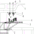
Fig. 1 is a schematic view of the structure of the present invention;
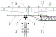
FIG. 2 is a schematic side view of the present invention;
in the drawing, 1, a concrete box girder 2, a pier 3, a corbel 4, a trolley 5, a suspender I6, a nut I7, a support plate 8, a rail 9, an electric block 10, an electric block roadster 11, a nose bridge 12, a suspender II 13 and a nut II are arranged.
Detailed Description
The present invention will be further explained with reference to fig. 1 and 2.
The utility model provides a novel lifting device is transported to moving die carrier dolly and bracket includes pier 2, sets up bracket 3 on pier 2, sets up dolly 4 on bracket 3 and is located the concrete box girder 1 of pier 2 top, still includes: the support plate 7 extends along the length direction of the nose bridge 11, the support plate 7 is fixed at the lower end of the concrete box girder 1 through a fixing device I, and the inner end of the support plate is fixed at the head end of the nose bridge 11 through a fixing device II; the rails 8 are horizontally arranged below the support plate 7, and the rails 8 are arranged along the front-back direction; the electric hoist sports car 10 is slidably mounted on the track 8; and an electric block 9 installed below the electric block sports car 10. Because the support plate 7 is fixed below the concrete box girder 1 by the fixing device I, and the inner side end of the support plate 7 is fixed at the head end of the nose bridge 11 by the fixing device II, the support plate 7 is fixedly installed by means of the concrete box girder 1 and the nose bridge 11, no additional auxiliary measures are needed, and the support plate 7 can reach a corresponding position by longitudinally moving along with the movable formwork. Electric block sports car 10 slides along track 8 to make electric block 9 remove to required position after, utilize electric block 9 to lift by crane back can follow the moving die carrier and indulge and move to bracket 3 and dolly 4, owing to adopt fixed point hoist and mount, saved the hoist and mount time, require significantly reduced to landing stage width and bearing, greatly save landing stage frame and erect the cost. The hoisting and transferring requirements of the corbels 3 in the small height space of the bottom surface of the concrete box girder and the trestle surface can be met.
Fixing device I can be following structure, and it includes a plurality of jibs I5, and the vertical setting of jib I5, its upper end passes behind concrete box girder 1 and utilizes nut I6 locking fixed, and its lower extreme passes behind extension board 7 and utilizes nut I6 locking fixed. The support plate 7 is hoisted by the suspender I5 and is fixed below the concrete box girder 1, and the installation and the disassembly are simple and convenient.
The fixing device II can be of a structure comprising a plurality of hanging rods II 12, the hanging rods II 12 are vertically arranged, the upper ends of the hanging rods II pass through the support plate 7 and then are locked and fixed through nuts II 13, and the lower ends of the hanging rods II pass through the nose bridge 11 and then are locked and fixed through nuts II 13. The head end of the support plate 7 is fixed above the nose bridge 11 by the suspension rod II 12, and the installation and the disassembly are simple and convenient.
Claims (3)
Priority Applications (1)
| Application Number | Priority Date | Filing Date | Title |
|---|---|---|---|
| CN202021397682.1U CN212769508U (en) | 2020-07-16 | 2020-07-16 | A new type of mobile formwork trolley and corbel transfer and hoisting equipment |
Applications Claiming Priority (1)
| Application Number | Priority Date | Filing Date | Title |
|---|---|---|---|
| CN202021397682.1U CN212769508U (en) | 2020-07-16 | 2020-07-16 | A new type of mobile formwork trolley and corbel transfer and hoisting equipment |
Publications (1)
| Publication Number | Publication Date |
|---|---|
| CN212769508U true CN212769508U (en) | 2021-03-23 |
Family
ID=75077939
Family Applications (1)
| Application Number | Title | Priority Date | Filing Date |
|---|---|---|---|
| CN202021397682.1U Expired - Fee Related CN212769508U (en) | 2020-07-16 | 2020-07-16 | A new type of mobile formwork trolley and corbel transfer and hoisting equipment |
Country Status (1)
| Country | Link |
|---|---|
| CN (1) | CN212769508U (en) |
Cited By (3)
| Publication number | Priority date | Publication date | Assignee | Title |
|---|---|---|---|---|
| CN114541267A (en) * | 2022-03-04 | 2022-05-27 | 中铁一局集团建筑安装工程有限公司 | Bridge girder erection machine capable of automatically unloading girder |
| CN115057336A (en) * | 2022-05-17 | 2022-09-16 | 中铁七局集团郑州工程有限公司 | Installation device for boom tray and boom nut of beam lifting machine |
| CN121205099A (en) * | 2025-11-28 | 2025-12-26 | 中交一航局第五工程有限公司 | A method for assembling mobile formwork in marine areas and its application |
-
2020
- 2020-07-16 CN CN202021397682.1U patent/CN212769508U/en not_active Expired - Fee Related
Cited By (6)
| Publication number | Priority date | Publication date | Assignee | Title |
|---|---|---|---|---|
| CN114541267A (en) * | 2022-03-04 | 2022-05-27 | 中铁一局集团建筑安装工程有限公司 | Bridge girder erection machine capable of automatically unloading girder |
| CN114541267B (en) * | 2022-03-04 | 2024-04-19 | 中铁一局集团建筑安装工程有限公司 | Bridge girder erection machine capable of automatically unloading girder |
| CN115057336A (en) * | 2022-05-17 | 2022-09-16 | 中铁七局集团郑州工程有限公司 | Installation device for boom tray and boom nut of beam lifting machine |
| CN115057336B (en) * | 2022-05-17 | 2023-04-07 | 中铁七局集团郑州工程有限公司 | Installation device for boom tray and boom nut of beam lifting machine |
| WO2023151702A1 (en) * | 2022-05-17 | 2023-08-17 | 中铁七局集团有限公司 | Mounting device for hoisting rod pallet and hoisting rod nut of girder crane |
| CN121205099A (en) * | 2025-11-28 | 2025-12-26 | 中交一航局第五工程有限公司 | A method for assembling mobile formwork in marine areas and its application |
Similar Documents
| Publication | Publication Date | Title |
|---|---|---|
| CN109653105B (en) | Main truss system of box girder bridge cantilever construction hanging basket and use method thereof | |
| CN201250064Y (en) | Front launching nose type bridge girder erection machine for bridge erection | |
| CN106917360A (en) | Lift leg formula frame plate machine and its frame plate method | |
| CN104594198A (en) | Method for erecting parallel box girders in tunnel | |
| CN108004929A (en) | A kind of H-type road-cum-rail bridge floorings hanging apparatus and hanging method | |
| CN106988314A (en) | A kind of counter weight type formwork jumbo, counter weight type outrigger platform, and construction method | |
| CN114933247B (en) | Intelligent construction equipment and its construction technology | |
| CN112320584B (en) | Three-dimensional bridge floor crane for steel box girder and steel box girder hoisting method | |
| CN214828467U (en) | A self-propelled block hoisting and transporting equipment | |
| CN103774564B (en) | Movable type bridge bearing replacement device | |
| CN112030777B (en) | A down-type mobile formwork support bracket spanning transfer construction method | |
| JP4551037B2 (en) | Large-scale PC slab erection method and apparatus | |
| CN209652772U (en) | Box girder bridge cantilever construction main truss cradle system | |
| CN204851299U (en) | Colliery is combined in pit and is adopted working face hydraulic support loading device | |
| CN117266040B (en) | Integral high-level carrying construction method of bridge girder erection machine | |
| CN108532462A (en) | A kind of symmetrically set a roof beam in place and its is set a roof beam in place, passing method at formula Bridge Erector | |
| CN110904861A (en) | Cable-stayed bridge girder erection crane and construction method thereof | |
| CN213679518U (en) | Asynchronous cradle with gantry crane | |
| CN110886240B (en) | Ultra-wide bridge girder erection machine | |
| CN211947971U (en) | A standardized multifunctional work trolley for bridge anti-collision wall | |
| CN212175493U (en) | Super-wide bridge erecting machine | |
| CN210105412U (en) | A side-support lift-type parking device without avoidance on the roadside | |
| CN203684097U (en) | Mountain overhead tower-attached cantilever type beam-lifting purlin-hoisting system | |
| CN117266041B (en) | A method for turning around on a bridge using a bridge erecting machine | |
| CN101381057A (en) | Large-sized gantry crane |
Legal Events
| Date | Code | Title | Description |
|---|---|---|---|
| GR01 | Patent grant | ||
| GR01 | Patent grant | ||
| CF01 | Termination of patent right due to non-payment of annual fee | ||
| CF01 | Termination of patent right due to non-payment of annual fee |
Granted publication date: 20210323 |