Plate polishing equipment
Technical Field
The utility model relates to a sheet material technical field that polishes specifically is a sheet material equipment of polishing.
Background
In the furniture production, the wood is mainly used as a raw material, and the furniture is processed by a mechanical or chemical method, so that the furniture product still keeps the basic characteristics of the wood. In wood processing, the wood needs to be sanded for uniform coating or painting. For satisfying the needs of a large amount of furniture, the batch polishing treatment of timber is often carried out by adopting a mechanical mode, namely, the timber is rapidly polished by adopting a polishing device, so that the polishing precision of the front surface and the back surface of a plate is inconsistent, and the polishing efficiency is not really improved. Along with the development of modern economy, the polishing requirement on wood in the furniture industry is higher and higher, and the existing wood polishing device cannot meet the requirements of high-quality and high-efficiency polishing. For example, chinese patent with publication number CN206066237U discloses a sheet polishing device, which includes a frame, a conveyor belt on the frame, and a polishing mechanism located above the conveyor belt; the polishing mechanism comprises a gantry type bracket, and a top plate, a lifting plate and a polishing head which are arranged from top to bottom; a through hole in clearance fit with the screw is formed in the center of the lifting plate, and the lower end of the screw penetrates through the through hole and is connected with a nut in fit with the through hole; guide rods penetrate through two sides of the top plate, the lower ends of the guide rods are fixedly connected with the lifting plate, and springs are sleeved on the guide rods between the top plate and the lifting plate; the lower surface of the lifting plate is provided with a motor, and the output end of the motor is connected with a polishing head.
However, the existing device does not fix the plate in the plate processing process, partial areas of the plate are easy to be not polished, and the two polishing heads have the same precision, so that repeated processing is caused, the production efficiency is reduced, and the processing cost is increased. There is a need for an improved design for this and we therefore propose a sheet grinding apparatus to solve the above problems.
Disclosure of Invention
Technical problem to be solved
Not enough to prior art, the utility model provides a sheet material equipment of polishing has solved the problem of sheet material subregion unprocessed and reprocess.
(II) technical scheme
In order to achieve the above object, the utility model provides a following technical scheme: a sheet material polishing device comprises a base plate, wherein the bottom of the base plate is fixedly connected with four fixing legs and a C-shaped block, the four fixing legs are arranged in a mutual symmetry manner in pairs, the top of the base plate is fixedly connected with six guide rails and a second motor, the six guide rails are arranged in a bilateral symmetry manner, each guide rail is connected with two slide blocks in a sliding manner, the tops of the six slide blocks positioned on the same side are fixedly connected with a same steel plate, the top of each steel plate is fixedly connected with two support columns, the two support columns are arranged in a mutual symmetry manner, the top ends close to the sides and the outer sides of the bottom ends of the support columns are respectively fixedly connected with two support rods, the two support rods are mutually symmetrical, the bottom of each steel plate is fixedly welded with two C-shaped plates, the inner sides of the C-shaped blocks are rotatably connected with positive and negative threaded rods, the outer sides, the other end of the rocker is hinged to the bottom of the corresponding square block, one end of the positive and negative screw rod is fixedly connected with a turntable, and the front side edge of the turntable is fixedly connected with a metal rod.
Preferably, the outer side of the supporting rod positioned at the same vertical center is rotatably sleeved with the movable guide wheels, and the four movable guide wheels are symmetrically arranged in pairs, so that the vertical shaking of the plate in the machining process is reduced, and the stability of the plate in the machining process is enhanced.
Preferably, the outside fixedly connected with auxiliary support rod's of support column one end, auxiliary support rod's other end fixed connection strengthens the stability of support column on corresponding steel sheet.
Preferably, the bar hole has been seted up at the top of bed plate, the inside rotation in bar hole is connected with a plurality of gyro wheels, and the gyro wheel is close to the one end fixedly connected with belt pulley of second motor, around being equipped with same root belt on the belt pulley, fixed connection is on corresponding belt pulley on the output shaft of second motor, and the sheet material moves on the gyro wheel, reduces frictional force, improves machining efficiency.
Preferably, four quad slits have been seted up at the top of bed plate, the mutual symmetry setting of quad slit two by two, the C template passes two quad slits of homonymy and contactless with the quad slit, and the C template passes the quad slit and drives the steel sheet and slide on the guide rail, improve equipment's intensity and stability.
Preferably, the top fixedly connected with first motor of steel sheet, two mutual symmetries of first motor set up, fixedly connected with polishing piece on the output shaft of first motor, two polishing pieces are polished the sheet material simultaneously, improve machining efficiency.
(III) advantageous effects
The utility model provides a panel equipment of polishing. The method has the following beneficial effects:
(1) this sheet material equipment of polishing, place between two polishing pieces through the one end with the sheet material, rotate the metal pole, the metal pole drives the anticlockwise (looking) rotation of carousel, the carousel drives positive and negative silk threaded rod and rotates, positive and negative silk threaded rod drives two square pieces and keeps away from each other, square piece drives the rocker and removes, rocker pulling C template removes, two C templates are close to each other, the corresponding steel sheet of C template pulling removes, the steel sheet drives the slider of fixing on the steel sheet, the slider removes on the guide rail, the removal leading wheel of both sides is close to each other with the piece of polishing, continue to rotate the metal pole on the carousel.
(2) According to the plate polishing equipment, when the movable guide wheels and the polishing pieces on the two sides contact the plate and cannot continuously approach the plate, the metal rod on the rotary table stops rotating. The first motor and the second motor are started simultaneously, the first motor drives the polishing disc to rotate, the polishing disc polishes the plate, the second motor drives the output end belt pulley to rotate, the belt pulley drives the idler wheel to rotate, the idler wheel drives the plate to move, the plate and the moving guide wheels on the two sides rotate relatively at the moment, the position of the plate is limited by the moving guide wheels on the two sides, and the plate is not prone to moving up and down in the machining process.
The utility model has the advantages of reasonable design, press from both sides through two sets of removal direction wheel to the clamp of sheet material and get the luffing motion phenomenon that can effectively reduce in the sheet material course of working, improve machining efficiency and quality, two polishing pieces are polished the sheet material simultaneously, improve machining efficiency.
Drawings
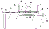
Fig. 1 is a schematic structural view of the present invention;
FIG. 2 is a schematic side view of the present invention;
fig. 3 is a schematic top view of the present invention;
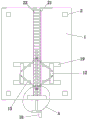
fig. 4 is a schematic structural view of the present invention viewed from the bottom;
FIG. 5 is an enlarged schematic view of part A of the present invention;
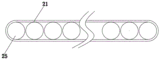
FIG. 6 is a schematic right side view of the belt and pulley connection of the present invention;
FIG. 7 is a partial schematic structural view of the cross section B-B of the C-shaped block and the positive and negative threaded rod of the present invention;
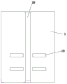
fig. 8 is a schematic structural view of the base plate of the present invention viewed from above.
In the figure: 1. a base plate; 2. a fixed leg; 3. a guide rail; 4. a slider; 5. a steel plate; 6. a first motor; 7. fixing a bracket; 8. a support pillar; 9. a support bar; 10. an auxiliary support bar; 11. moving the guide wheel; 12. c-shaped plates; 13. a rocker; 14. a turntable; 15. a metal rod; 16. a C-shaped block; 17. grinding the sheets; 18. positive and negative thread threaded rod; 19. a square hole; 20. a second motor; 21. a belt; 22. a roller; 23. a square block; 24. a threaded hole; 25. a belt pulley; 26. and (4) strip-shaped holes.
Detailed Description
The technical solutions in the embodiments of the present invention will be described clearly and completely with reference to the accompanying drawings in the embodiments of the present invention, and it is obvious that the described embodiments are only some embodiments of the present invention, not all embodiments. Based on the embodiments in the present invention, all other embodiments obtained by a person skilled in the art without creative work belong to the protection scope of the present invention.
As shown in fig. 1-8, the utility model provides a technical solution: a sheet material polishing device comprises a base plate 1, wherein the bottom of the base plate 1 is fixedly connected with four fixing legs 2 and C-shaped blocks 16, every two of the four fixing legs 2 are symmetrically arranged, the top of the base plate 1 is fixedly connected with six guide rails 3 and a second motor 20, the six guide rails 3 are symmetrically arranged left and right, each guide rail 3 is slidably connected with two sliders 4, the tops of the six sliders 4 positioned on the same side are fixedly connected with the same steel plate 5, the top of each steel plate 5 is fixedly connected with two support columns 8, the two support columns 8 are symmetrically arranged, the top ends and the outer sides of the bottom ends of the adjacent sides of the support columns 8 are respectively fixedly connected with two support rods 9, the two support rods 9 are mutually symmetrical, the bottom of each steel plate 5 is fixedly welded with two C-shaped plates 12, the inner sides of the C-shaped blocks 16 are rotatably connected with positive and negative threaded rods 18, and the outer sides, the bottom of each C-shaped plate 12 is hinged with one end of each rocker 13, the other end of each rocker 13 is hinged with the bottom of the corresponding square block 23, one end of each positive and negative threaded rod 18 is fixedly connected with a rotary table 14, and the front side edge of each rotary table 14 is fixedly connected with a metal rod 15.
The utility model discloses in, the outside that is located the bracing piece 9 at same vertical center is rotated and has been cup jointed and has been removed leading wheel 11, four remove 11 two liang of mutual symmetries of leading wheel and set up, reduce the upper and lower shake of sheet material in the course of working, the stability of sheet material in the reinforcing course of working.
The utility model discloses in, the outside fixedly connected with auxiliary stay pole 10's of support column 8 one end, auxiliary stay pole 10's other end fixed connection strengthens the stability of support column on corresponding steel sheet 5.
The utility model discloses in, bar hole 26 has been seted up at the top of bed plate 1, the inside rotation in bar hole 26 is connected with a plurality of gyro wheels 22, and gyro wheel 22 is close to second motor 20's one end fixedly connected with belt pulley 25, around being equipped with same root belt 21 on the belt pulley 25, fixed connection is on corresponding belt pulley 25 on second motor 20's the output shaft, and the sheet material moves on the gyro wheel, reduces frictional force, improves machining efficiency.
The utility model discloses in, four quad slit 19 have been seted up at the top of bed plate 1, two liang of mutual symmetries of quad slit 19 set up, C template 12 pass two quad slit 19 of homonymy and with 19 contactless of quad slit, the C template passes the quad slit and drives the steel sheet and slide on the guide rail, improve equipment's intensity and stability.
The utility model discloses in, the first motor 6 of top fixedly connected with of steel sheet 5, two mutual symmetries of first motor 6 set up, fixedly connected with polishing piece 17 on the output shaft of first motor 6, two polishing pieces polish the sheet material simultaneously, improve machining efficiency.
In conclusion, when the plate polishing equipment is used, one end of a plate is placed between two polishing sheets 17, the metal rod 15 is rotated, the metal rod 15 drives the turntable 14 to rotate anticlockwise (in a front view), the turntable 14 drives the positive and negative threaded rod 18 to rotate, the positive and negative threaded rod 18 drives the two square blocks 23 to move away from each other, the square blocks 23 drive the rocker 13 to move, the rocker 13 drives the C-shaped plates 12 to move, the two C-shaped plates 12 approach each other, the C-shaped plates 12 drive the corresponding steel plates 5 to move, the steel plates 5 drive the sliding blocks 4 fixed on the steel plates 5, the sliding blocks 4 move on the guide rails 3, the moving guide wheels 11 and the polishing sheets 17 on the two sides approach each other, the metal rod 15 on the turntable 14 is continuously rotated, when the moving guide wheels 11 and the grinding plates 17 on the two sides contact the plate and cannot be continuously close to each other, the metal rod 15 on the rotary table 14 stops rotating. The first motor 6 and the second motor 20 are started simultaneously, the first motor 6 drives the polishing disc 17 to rotate, the polishing disc 17 polishes the plate, the second motor 20 drives the output end belt pulley 25 to rotate, the belt pulley 25 drives the idler wheel 22 to rotate, the idler wheel 22 drives the plate to move, the plate and the moving guide wheels 11 on the two sides rotate relatively at the moment, the position of the plate is limited by the moving guide wheels 11 on the two sides, and the plate is not prone to moving up and down in the machining process.
It is noted that, herein, relational terms such as first and second, and the like may be used solely to distinguish one entity or action from another entity or action without necessarily requiring or implying any actual such relationship or order between such entities or actions. Also, the terms "comprises," "comprising," or any other variation thereof, are intended to cover a non-exclusive inclusion, such that a process, method, article, or apparatus that comprises a list of elements does not include only those elements but may include other elements not expressly listed or inherent to such process, method, article, or apparatus. Without further limitation, an element defined by the phrase "comprising an … …" does not exclude the presence of other identical elements in a process, method, article, or apparatus that comprises the element.
Although embodiments of the present invention have been shown and described, it will be appreciated by those skilled in the art that changes, modifications, substitutions and alterations can be made in these embodiments without departing from the principles and spirit of the invention, the scope of which is defined in the appended claims and their equivalents.