SUMMERY OF THE UTILITY MODEL
In order to solve the above problems, a silicon material pre-cleaning machine is proposed. In order to achieve the above object, the utility model provides a following technical scheme:
the utility model provides a silicon material cleaning machine in advance, is including being used for carrying wait to wash the conveying mechanism of silicon material, being used for treating the brush clearance mechanism that impurity on wasing the silicon material carries out the clearance and be used for treating to wash the silicon material and carry out high pressure spray abluent high pressure and spray wiper mechanism, brush clearance mechanism includes brush subassembly and a plurality of rotatable brush subassemblies down on a plurality of rotatoryly, and a plurality of brush subassembly intervals of going up set up in conveying mechanism's top and are used for wasing the upper portion and the side of silicon material, and a plurality of brush intervals down set up the bottom surface that is used for clearing up the silicon material on conveying mechanism, it is chain gear drive with lower brush subassembly to go up the brush subassembly.
Preferably, a plurality of brush subassemblies of going up divide into two along the direction that conveying mechanism carried, and two are listed as and go up the setting of brush subassembly one-to-one, go up the brush subassembly include first rotation axis and set up in the brush fixed disk of first rotation axis one end with be loudspeaker form install in go up the brush on the periphery circle of brush fixed disk, the one end that the brush fixed disk was kept away from to first rotation axis is provided with first gear, and every brush subassembly all corresponds and is provided with first chain and first motor on going up, is located the first gear on the last brush subassembly of same row and realizes synchronous revolution under the effect of the first chain that corresponds the setting and first motor.
Preferably, guide gears are respectively arranged on two sides of the first motor, and the first chain is positively and negatively connected to two adjacent gears.
Preferably, the lower brush assembly comprises a second rotating shaft, a brush roller and a lower brush, the brush roller rotates along with the second rotating shaft on the second rotating shaft, the lower brush is arranged on the brush roller and comprises a plurality of second brush wires, the second brush wires are distributed in an annular array on the brush roller, a second gear is arranged at one end of the second rotating shaft, a second chain and a second motor are arranged on the second gear corresponding to the lower brush assemblies, and the second gears of the lower brush assemblies rotate synchronously under the action of the second chain and the second motor.
Preferably, the high-pressure spray cleaning mechanism comprises a plurality of upper spray assemblies, a plurality of lower spray assemblies and a water storage tank for recovering spray water, the upper spray assemblies are arranged above the conveying mechanism and used for spraying and cleaning the upper part and the side surface of the silicon material, the upper spray assemblies and the upper brush assemblies are arranged at intervals, the lower spray assemblies are arranged below the conveying mechanism and used for cleaning the bottom surface of the silicon material, and the water storage tank is arranged below the lower spray assemblies.
Preferably, the water storage tank is set to be a T-shaped structure, an opening at the upper part of the water storage tank is matched with the size of the conveying mechanism and used for recovering spraying water for cleaning the silicon material, and the lower part of the water storage tank is a box body structure and used for storing water and transferring the recovered water to a water circulation system or a sewage discharge system through a pipeline for sewage discharge centralized treatment.
Preferably, the upper spray assembly comprises an upper spray pipe and a high-pressure water pump, the upper spray pipe is connected to the high-pressure water pump through a pipeline, a plurality of first nozzles for spraying water downwards are arranged on the upper spray pipe, the lower spray assembly comprises a lower spray pipe, the lower spray pipe is connected to the high-pressure water pump through a pipeline, and a plurality of second nozzles for spraying water upwards are arranged on the lower spray pipe.
Preferably, conveying mechanism includes a plurality of transport rollers that set up side by side, sets up and leaves the clearance that supplies the spun water under high pressure of second nozzle to pass through between the transport roller of spraying assembly top down, the one end of carrying the roller is provided with the third gear, and the third gear that corresponds a plurality of transport rollers is provided with third chain and third motor, and the third gear of a plurality of transport rollers realizes synchronous revolution under the effect of third chain and third motor.
Preferably, the outer side of the conveying roller is provided with a polyurethane rubber coating layer.
Preferably, the device comprises a main frame, wherein the conveying mechanism, the high-pressure spray cleaning mechanism and the brush cleaning mechanism are arranged on the main frame, a fixing plate is arranged on the upper portion of the upper brush assembly, the upper portion of the upper brush assembly is rotatably arranged on the fixing plate, and the fixing plate is fixedly arranged on the main frame.
Preferably, a polypropylene shell for preventing silicon material from being polluted and preventing high-pressure spray water from splashing is arranged on the outer side of the main frame.
Has the advantages that:
the utility model provides a silicon material pre-cleaning machine, this silicon material pre-cleaning machine carries the silicon material of treating the washing through conveying mechanism, go up brush subassembly cooperation upper spray assembly and clear up the upper portion and the side of silicon material, lower brush subassembly cooperation lower spray assembly clears up the bottom surface of silicon material, the clearance of this silicon material pre-cleaning machine treatment silicon material has been realized, upper brush subassembly and lower brush subassembly all set up to a plurality ofly, clear up the silicon material repeatedly, upper spray assembly and lower spray assembly all set up to a plurality ofly, cooperate upper brush subassembly and lower brush subassembly to wash the silicon material repeatedly, remove silicon material surface spot, silicon mud, silicon powder, guaranteed the clean thorough of silicon material clearance; this silicon material washs machine in advance has improved production efficiency greatly, has saved the cost of labor, and easy operation is understandable, and safety and environmental protection more washs cleaner, has improved silicon material quality greatly.
Detailed Description
In order to make those skilled in the art better understand the technical solution of the present invention, the following description, together with the drawings of the present invention, clearly and completely describes the technical solution of the present invention, and based on the embodiments in the present application, other similar embodiments obtained by those skilled in the art without creative efforts shall all belong to the protection scope of the present application. In addition, directional terms such as "upper", "lower", "left", "right", etc. in the following embodiments are directions with reference to the drawings only, and thus, the directional terms are used for illustration and not for limitation of the present invention.
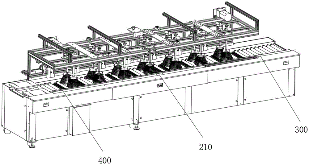
As shown in fig. 1, 2 and 3, the silicon material pre-cleaning machine provided in this embodiment includes a main frame 100, a conveying mechanism 300 for conveying a silicon material to be cleaned, a brush cleaning mechanism for cleaning impurities on the silicon material to be cleaned, and a high-pressure spray cleaning mechanism for high-pressure spray cleaning the silicon material to be cleaned, wherein the conveying mechanism 300, the high-pressure spray cleaning mechanism, and the brush cleaning mechanism are all disposed on the main frame 100, the silicon material to be cleaned is placed at a front end of the conveying mechanism 300, i.e. a loading position, and is conveyed by the conveying mechanism 300 to move forward to the brush cleaning mechanism and the high-pressure spray cleaning mechanism, the silicon material to be cleaned continues to move forward on the conveying mechanism 300 while being cleaned and cleaned by the brush cleaning mechanism and the high-pressure spray cleaning mechanism until the silicon material is conveyed out of a region where the brush cleaning mechanism and the high-pressure spray cleaning mechanism are located, the silicon material continues to move forward by a distance to a rear end of the conveying mechanism 300, i.e., this silicon material cleaning machine's material loading position and unloading position are located conveying mechanism 300's both ends respectively, and brush clearance mechanism and high pressure spray wiper mechanism are located between material loading position and the unloading position, and brush clearance mechanism and high pressure spray wiper mechanism mutually support, and brush clearance mechanism treats and washs silicon material surface spot, silicon mud, silica flour etc. and clear up, and high pressure spray wiper mechanism treats abluent silicon material and washs, realizes quick, convenient, high-efficient, thorough washing to the silicon material.
The conveying mechanism 300 comprises a plurality of conveying rollers arranged side by side, a third gear is arranged at one end of each conveying roller, third bearings are arranged at two ends of each conveying roller, the third bearings at one ends of the conveying rollers provided with the third gears are located on the inner sides of the third gears, and the conveying rollers are rotatably connected to the main frame 100 through the third bearings. The third gears corresponding to the conveying rollers are provided with a third chain and a third motor, the third gears of the conveying rollers synchronously rotate under the action of the third chain and the third motor, so that the purpose of conveying silicon materials by the conveying rollers is realized, a water permeable gap is reserved between every two adjacent conveying rollers and is smaller than the size of the silicon materials, and the silicon materials are prevented from leaking from the water permeable gap.
Further, the outside of carrying the roller is provided with polyurethane rubber coating, and polyurethane rubber coating can guarantee that silicon material can not cause secondary pollution to silicon material at the cleaning process, carries the roller.
Brush clearance mechanism includes brush subassembly 210 and a plurality of rotatable brush subassembly 400 down on a plurality of rotatoryly, brush subassembly 210 interval sets up in the upper portion and the side that are used for wasing the silicon material in conveyor 300's top on a plurality of, a plurality of brush subassembly 210 that go up divide into two along the direction that conveyor 300 carried, brush subassembly 210 one-to-one sets up on two, form the structure of two multirow in conveyor 300's top, in this embodiment, a plurality of brush subassembly 210 that go up are established to two seven rows along the direction that conveyor 300 carried, brush subassembly 210 clears up the silicon material repeatedly on seven rows, the cleanliness factor to the silicon material clearance has been guaranteed. The lower brushes are arranged on the conveying mechanism 300 at intervals and used for cleaning the bottom surface of the silicon material, and the upper brush assembly 210 and the lower brush assembly 400 are in chain gear transmission.
As shown in FIG. 4, the upper brush assembly 210 is provided at an upper portion thereof with a fixing plate 500, the fixing plate 500 is formed in an L-shaped structure by a horizontal plate and a vertical plate, the upper brush assembly 210 is mounted on the main frame 100 via the horizontal plate, and the upper portion of the upper brush assembly 210 is rotatably mounted on the vertical plate of the fixing plate 500.
Go up brush subassembly 210 and include first rotation axis 211 and set up in the brush fixed disk 212 of first rotation axis 211 one end and the last brush 213 of installing on the outer periphery circle of brush fixed disk 212 of loudspeaker form, it includes a plurality of first brush silks to go up brush 213, first brush silk leans out and is 10-40 with the contained angle of vertical direction, preferably 24, it intersects the setting to be located the last brush 213 of going up brush subassembly 210 of same row, first brush silk leans out, the tubaeform structure of going up brush 213 has realized being located the crossing setting of last brush subassembly 210 of same row promptly, this setting can make the coverage of going up brush 213 wide, and can be to all-round washing of silicon material. Further, the length of first brush silk is inhomogeneous, and this makes upper brush 213 clear up the upper portion and the side of silicon material, and longer first brush silk washs the side of silicon material, and shorter brush silk clears up the upper portion of silicon material, and this setting has strengthened upper brush 213's cleaning performance for the washing of silicon material is cleaner.
The brush fixing plate 2 is fixedly installed at one end of a first rotating shaft 211, the other end of the first rotating shaft 211 is provided with a first gear 215, each row of brush assemblies 210 is correspondingly provided with a first chain 240 and a first motor 220, the first motor is provided with a transmission gear 221, two sides of the first motor 220 are respectively provided with a guide gear 230, the guide gear 230 and the transmission gear 221 are positioned at one side of the first gear 215 on the upper brush assembly 210 in the same row, the first chain 240 is synchronously rotated under the action of the transmission gear 221, the guide gear 230, the plurality of first gears 215 on the upper brush assemblies 210 in the same row and the guide gear 230, the first gear 215 on the upper brush assembly 210 in the same row is sequentially positively and negatively connected to two adjacent gears, the first gear 215 on the upper brush assembly 210 in the same row is synchronously rotated under the action of the first chain 240 and the first motor 220 correspondingly arranged, so that the first rotating shaft 211 is rotated, and the first rotating shaft 211, therefore, the upper hairbrush 213 can clean impurities on the silicon material.
As shown in fig. 5, the lower brush assembly 400 includes a second rotating shaft 410, a brush roller 420 disposed on the second rotating shaft 410 and rotating with the second rotating shaft 410, and a lower brush disposed on the brush roller 420, wherein the lower brush includes a plurality of second brush filaments 421, and the plurality of second brush filaments 421 are distributed on the brush roller 420 in an annular array.
One end of the second rotating shaft 410 is provided with a second gear 430, the second gear 430 corresponding to the plurality of lower brush assemblies 400 is provided with a second chain and a second motor, the second gears 430 of the plurality of lower brush assemblies 400 rotate synchronously under the action of the second chain and the second motor, so that the second rotating shaft 400 rotates, the second rotating shaft 410 drives the brush roller 420 to rotate, and the cleaning of the upper impurities of the silicon material by the brush roller 420 is realized. Both ends of the second rotating shaft 410 are provided with second bearings 440, the second bearing 440 provided at one end of the second gear 430 is provided at the inner side of the second gear 430 on the second rotating shaft 410, and the lower brush assembly 400 is mounted on the main frame 100 through the second bearings 440.
Further, the number of the second gears 430 is 2, two second chains are correspondingly arranged corresponding to the 2 second gears 430, the 2 second gears 430 are respectively matched with the two second chains to realize synchronous transmission, and the stable rotation of the second rotating shaft 410 is realized by the arrangement.
Further, the upper brush 213 and the lower brush are both nylon banister brushes, and the arrangement of the nylon banister brushes ensures that the upper brush 213 and the lower brush can not only ensure the cleanliness of silicon material cleaning, but also ensure that the upper brush 213 and the lower brush cannot cause damage or secondary pollution to the silicon material.
High pressure sprays wiper mechanism includes a plurality of spray assembly of going up, a plurality of spray assembly down and be used for retrieving the storage water tank that sprays the water, a plurality of spray assembly of going up set up in conveying mechanism 300's top and be used for spraying the washing to the upper portion and the side of silicon material, a plurality of spray assembly of going up set up with a plurality of brush subassembly 210 intervals of going up, it includes shower and high pressure water pump to go up spray assembly, it passes through pipe connection on high pressure water pump to go up the shower, upward be provided with the first nozzle of a plurality of water sprays downwards on the shower, it realizes carrying out limit clearance limit washing to the upper portion and the side of silicon material with last brush subassembly 210 cooperation to go up spray assembly, it is thoroughly clean to silicon material upper portion and side abluent has been guaranteed.
A plurality of lower spray assembly intervals set up and are used for wasing the bottom surface of silicon material in conveying mechanism 300's below, lower spray assembly includes shower down, lower shower passes through pipe connection on high pressure water pump, be provided with a plurality of second nozzles that upwards spray on the shower down, set up and leave the clearance that supplies second nozzle spun water under high pressure to pass through between the transport roller of spray assembly top down, lower spray assembly realizes wasing the bottom surface of silicon material while clearing up with lower brush subassembly 400 cooperation, it is thoroughly clean to have guaranteed silicon material bottom surface washing.
The storage water tank sets up in the below of spraying the subassembly down, and the storage water tank sets up to T shape structure, and the upper portion opening part of storage water tank is used for retrieving to carry out abluent water of spraying to the silicon material with the size matching of conveying mechanism 300, and the lower part of storage water tank is that the box structure is used for storing water and changes the water of retrieving to water circulating system or change to sewage disposal system and carry out blowdown centralized processing through the pipeline. The outer side of the main frame 100 is provided with a polypropylene case for preventing the silicon material from being polluted and preventing high-pressure shower water from being splashed out.
This silicon material cleaning machine is when using, at first to the material loading position material loading, silicon material moves to brush clearance mechanism and high pressure under conveying mechanism 300's effect and sprays wiper mechanism department to clear up and wash, treat that the silicon material that washs continues to advance on conveying mechanism 300 in brush clearance mechanism and high pressure spray wiper mechanism's clearance and abluent, until carrying out the silicon material out brush clearance mechanism and the region that wiper mechanism place is sprayed to high pressure, continue to carry and carry out the unloading to the unloading position, accomplish the washing, and convenient for operation washs high-efficiently and totally.
It is obvious to a person skilled in the art that the invention is not restricted to details of the above-described exemplary embodiments, but that it can be implemented in other specific forms without departing from the spirit or essential characteristics of the invention. The present embodiments are therefore to be considered in all respects as illustrative and not restrictive, the scope of the invention being indicated by the appended claims rather than by the foregoing description, and all changes which come within the meaning and range of equivalency of the claims are therefore intended to be embraced therein. Any reference sign in a claim should not be construed as limiting the claim concerned.
Furthermore, it should be understood that although the present description refers to embodiments, not every embodiment may contain only a single embodiment, and such description is for clarity only, and those skilled in the art should integrate the description, and the embodiments may be combined as appropriate to form other embodiments understood by those skilled in the art.