CN212753598U - A automatic watering device for landscape architecture - Google Patents
A automatic watering device for landscape architecture Download PDFInfo
- Publication number
- CN212753598U CN212753598U CN202021575478.4U CN202021575478U CN212753598U CN 212753598 U CN212753598 U CN 212753598U CN 202021575478 U CN202021575478 U CN 202021575478U CN 212753598 U CN212753598 U CN 212753598U
- Authority
- CN
- China
- Prior art keywords
- water pipe
- water
- pipe
- fixedly provided
- rack
- Prior art date
- Legal status (The legal status is an assumption and is not a legal conclusion. Google has not performed a legal analysis and makes no representation as to the accuracy of the status listed.)
- Expired - Fee Related
Links
- XLYOFNOQVPJJNP-UHFFFAOYSA-N water Substances O XLYOFNOQVPJJNP-UHFFFAOYSA-N 0.000 claims abstract description 109
- 238000010438 heat treatment Methods 0.000 claims description 5
- 239000003643 water by type Substances 0.000 abstract description 4
- 241000196324 Embryophyta Species 0.000 description 5
- 230000008901 benefit Effects 0.000 description 3
- 230000004048 modification Effects 0.000 description 3
- 238000012986 modification Methods 0.000 description 3
- 238000005516 engineering process Methods 0.000 description 2
- 239000002351 wastewater Substances 0.000 description 2
- 230000007547 defect Effects 0.000 description 1
- 238000012423 maintenance Methods 0.000 description 1
- 238000011084 recovery Methods 0.000 description 1
- GOLXNESZZPUPJE-UHFFFAOYSA-N spiromesifen Chemical compound CC1=CC(C)=CC(C)=C1C(C(O1)=O)=C(OC(=O)CC(C)(C)C)C11CCCC1 GOLXNESZZPUPJE-UHFFFAOYSA-N 0.000 description 1
- 239000007921 spray Substances 0.000 description 1
Images


Landscapes
- Special Spraying Apparatus (AREA)
Abstract
The utility model discloses an automatic watering device for landscape architecture, concretely relates to watering technical field, which comprises a tank body, the fixed casing that is equipped with in jar body one side, the fixed motor that is equipped with in the inside bottom of casing, the fixed gear that is equipped with of motor output shaft, the inside square pipe that is equipped with of casing, the fixed rack that is equipped with in square pipe one side, square pipe and rack run through the casing, the rack is established in gear one side, rack and gear intermeshing, the fixed first water pipe that is equipped with in square pipe top, the fixed rotatory nozzle that is equipped with in first water pipe top. The utility model discloses a thereby the rotatory rack that drives of gear that drives on the output shaft of motor output shaft and square pipe remove, and the removal of square pipe makes rotatory nozzle can evenly water for the plant leaf of co-altitude not, waters efficient and water economy resource and cost of labor.
Description
Technical Field
The embodiment of the utility model provides a relate to the technical field of the device that waters, concretely relates to automatic watering device for landscape architecture.
Background
Landscaping is an aesthetic natural environment and a rest area created by applying engineering technology and artistic means in a certain region and modifying the terrain (or further building mountains, stacking stones and managing water) to plant trees, flowers and plants, building buildings, arranging garden roads and the like, is called as a garden, and is a vital item for watering in the maintenance work of the garden.
The prior art has the following defects: the common watering work is that people hold a water pipe to water the tree roots or the leaves, but the manual watering of the leaves is uneven, the watering efficiency is low, water resources are wasted, and meanwhile, the labor cost is high.
SUMMERY OF THE UTILITY MODEL
Therefore, the embodiment of the utility model provides an automatic watering device for landscape architecture, thereby it drives rack and square pipe removal to drive the rotatory gear that drives output shaft through the rotation of motor output shaft, the removal of square pipe makes rotatory nozzle can evenly water for the plant leaf of co-altitude not, water efficient and water economy resource and cost of labor, water with solve among the prior art because the work of watering of common is that the manual work is held the water pipe and is facing root of a tree or leaf watering, but the manual work is watered for the leaf inhomogeneous results in watering inefficiency and can waste water resources, also have the problem of high cost of labor simultaneously.
In order to achieve the above object, the embodiment of the present invention provides the following technical solutions: an automatic watering device for landscape and garden comprises a tank body, wherein a second water pipe is fixedly arranged at the bottom end of the tank body, a third water pipe is fixedly arranged at the bottom end of the second water pipe, a second hose is fixedly arranged at one end of the third water pipe, a third hose is fixedly arranged at the other end of the third water pipe, a shell is fixedly arranged on one side of the tank body, a motor is fixedly arranged at the bottom end in the shell, a gear is fixedly arranged on an output shaft of the motor, a square pipe is arranged in the shell, a rack is fixedly arranged on one side of the square pipe, the square pipe and the rack penetrate through the shell, the rack is arranged on one side of the gear, the rack and the gear are mutually meshed, a first water pipe is fixedly arranged at the top end of the square pipe, the first water pipe is communicated with the interior of the square pipe, a water receiving box is fixedly arranged at the outer end of the first water pipe, the first water, one end of the second hose extends into the bottom end of the square tube.
Further, a second filter screen is fixedly arranged at the top end of the tank body.
Further, the top end of the water receiving box is fixedly provided with a first filter screen, the first filter screen is fixedly arranged at the outer end of the first water pipe, the bottom end of the water receiving box is fixedly provided with a first hose, one end of the first hose penetrates through the second filter screen and extends into the tank body, and the first hose is arranged on one side of the rack.
Furthermore, a heating pipe is fixedly arranged on the inner wall of the tank body.
Further, a booster pump and two electric valves are fixedly arranged on the third water pipe, the two electric valves are respectively arranged on two sides of the second water pipe, the booster pump is arranged between the second hose and one of the electric valves, and the top end of the booster pump is fixedly connected with the bottom end of the tank body.
Further, an external water pipe is fixedly arranged on the other side of the tank body, the external water pipe extends into the tank body, a ball float valve is fixedly arranged at one end of the external water pipe, and the ball float valve is arranged in the tank body.
Further, a baffle is fixedly arranged at the bottom end of one side of the square pipe and is arranged at the bottom of the shell.
Further, jar body bottom mounting is equipped with four supporting legs.
The embodiment of the utility model provides a have following advantage:
the utility model discloses a thereby the rotatory rack that drives of gear that drives on the output shaft of motor output shaft and square pipe remove for rotatory nozzle removes not co-altitude and waters, compares with prior art, and square pipe's removal makes rotatory nozzle can evenly water for the plant leaf of co-altitude, waters efficiently and water economy resource and cost of labor.
Drawings
In order to more clearly illustrate the embodiments of the present invention or the technical solutions in the prior art, the drawings used in the description of the embodiments or the prior art will be briefly described below. It should be apparent that the drawings in the following description are merely exemplary, and that other embodiments can be derived from the drawings provided by those of ordinary skill in the art without inventive effort.
The structure, ratio, size and the like shown in the present specification are only used for matching with the content disclosed in the specification, so as to be known and read by people familiar with the technology, and are not used for limiting the limit conditions which can be implemented by the present invention, so that the present invention has no technical essential significance, and any structure modification, ratio relationship change or size adjustment should still fall within the scope which can be covered by the technical content disclosed by the present invention without affecting the efficacy and the achievable purpose of the present invention.
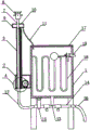
Fig. 1 is a schematic view of a front sectional structure provided by the present invention;
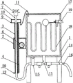
FIG. 2 is a schematic view of a descending cross-sectional structure of the device provided by the present invention;
fig. 3 is a schematic view of a top cross-sectional structure of the housing provided by the present invention;
FIG. 4 is an enlarged view of the portion A in FIG. 1 according to the present invention;
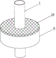
fig. 5 is a schematic view of a three-dimensional structure of the water receiving box provided by the utility model;
in the figure: 1 tank body, 2 shells, 3 square pipes, 4 racks, 5 motors, 6 gears, 7 first water pipes, 8 rotary nozzles, 9 water receiving boxes, 10 first filter screens, 11 first hoses, 12 second hoses, 13 second water pipes, 14 third water pipes, 15 booster pumps, 16 third hoses, 17 second filter screens, 18 heating pipes, 19 external water pipes and 20 baffle plates.
Detailed Description
The present invention is described in terms of specific embodiments, and other advantages and benefits of the present invention will become apparent to those skilled in the art from the following disclosure. Based on the embodiments in the present invention, all other embodiments obtained by a person skilled in the art without creative work belong to the protection scope of the present invention.
Referring to the attached drawings 1-5 of the specification, the automatic watering device for landscape architecture of the embodiment comprises a tank body 1, a second water pipe 13 is fixedly arranged at the bottom end of the tank body 1, a third water pipe 14 is fixedly arranged at the bottom end of the second water pipe 13, a second hose 12 is fixedly arranged at one end of the third water pipe 14, a third hose 16 is fixedly arranged at the other end of the third water pipe 14, a shell 2 is fixedly arranged at one side of the tank body 1, a motor 5 is fixedly arranged at the bottom end inside the shell 2, a gear 6 is fixedly arranged at an output shaft of the motor 5, a square pipe 3 is arranged inside the shell 2, a rack 4 is fixedly arranged at one side of the square pipe 3, the square pipe 3 and the rack 4 penetrate through the shell 2, the rack 4 is arranged at one side of the gear 6, the rack 4 and the gear 6 are mutually meshed, a first water pipe 7 is fixedly arranged at the top end of the square pipe 3, the first water pipe, the fixed water receiving box 9 that is equipped with in first water pipe 7 outer end, first water pipe 7 is established at 2 tops of casing, the fixed rotatory nozzle 8 that is equipped with in first water pipe 7 top, the inside bottom of square 3 pipe of second hose 12 one end extension income.
Further, jar body 1 top is fixed and is equipped with second filter screen 17, and second filter screen 17 can prevent debris such as fallen leaves from falling into jar body 1, and rainwater also can get into jar body 1 through second filter screen 17 during rainy by make full use of.
Further, 9 fixed first filter screens 10 that are equipped with in top of water receiving box, first filter screen 10 is fixed to be established in 7 outer ends of first water pipe, 9 bottom fixings of water receiving box are equipped with first hose 11, first hose 11 one end runs through second filter screen 17 and extends into jar internal portion 1, first hose 11 is established in 4 one sides of rack, and water receiving box 9 can be with 8 drippage of rotatory nozzle's water recovery through first hose 11 reentrant jar body 1, and first filter screen 10 prevents that leaf or other debris from dropping into and blockking up first hose 11 in the water receiving box 9.
Further, a heating pipe 18 is fixedly arranged on the inner wall of the tank body 1, and the heating pipe 18 can heat and melt ice when the ice is frozen in winter.
Further, fixed booster pump 15 and two electric valve that are equipped with on the third water pipe 14, two electric valve establishes respectively in second water pipe 13 both sides, booster pump 15 establishes between second hose 12 and one of them electric valve, 15 tops of booster pump and 1 bottom fixed connection of jar body, electric valve can control respectively and water for root of a tree and leaf, and booster pump 15 can increase water pressure when watering for the leaf.
Further, the fixed external water pipe 19 that is equipped with of 1 opposite side of the jar body, external water pipe 19 extends into jar 1 inside of the body, the fixed ball-cock assembly that is equipped with of 19 one end of external water pipe, the ball-cock assembly is established inside jar 1, and the ball-cock assembly can the automatic control jar inflow in 1, does not need manual intervention.
Further, the bottom end of one side of the square tube 3 is fixedly provided with a baffle 20, the baffle 20 is arranged at the bottom of the shell 2, and the baffle 20 can block the square tube 3 from completely entering the shell 2 when the square tube 3 moves upwards.
Further, 1 bottom mounting of the jar body is equipped with four supporting legs, and the supporting leg can support fixed jar body 1.
The implementation scenario is specifically as follows: water enters the tank body 1 from the external water pipe 19, when the water level reaches a certain height, the ball float valve is automatically closed to forbid water inflow, when the water level descends, the ball float valve is automatically opened to admit water, when the water level is watered, the electric valve at one end of the third water pipe 14 connected with the second filter screen 17 is opened, the water flows into the third hose 16 from the tank body 1 through the second water pipe 13 and the third water pipe 14, the outer end of the third hose 16 is opposite to the tree root, when the leaves are watered, the other electric valve and the booster pump 15 on the third water pipe 14 are opened, the water flows into the second hose 12 from the tank body 1 through the second water pipe 13 and the third water pipe 14, then flows into the square pipe 3 from the second hose 12 and then enters the first water pipe 7, the water passes through the first water pipe 7 and is sprayed out through the rotary spray nozzle 8, during the period, the motor 5 is started, the output shaft of the motor 5 rotates to drive the gear 6 on the output shaft to rotate, the gear 6 rotates, rack 4 drives square pipe 3 and removes, thereby make square pipe 3 remove the not co-altitude watering, the water that drips above the water receiving box 9 catches, when water receiving box 9 removes to being higher than jar body 1 top along with square pipe 3, the water that connects in the water receiving box 9 flows into jar body 1 by first hose 11 in, the removal of square pipe 3 makes rotatory nozzle 8 can water for the plant leaf of co-altitude evenly, water efficient and cost such as water economy resource, and this embodiment has specifically solved common work of watering among the prior art is that the manual work is held the water pipe and is faced root of a tree or leaf watering, but the manual work is watered the leaf inhomogeneous, water inefficiency and can waste water resource, also have high cost of labor's problem simultaneously.
Although the invention has been described in detail with respect to the general description and the specific embodiments, it will be apparent to those skilled in the art that modifications and improvements can be made based on the invention. Therefore, such modifications and improvements are intended to be within the scope of the invention as claimed.
Claims (8)
1. An automatic watering device for landscape architecture, which comprises a tank body (1), and is characterized in that: the tank body (1) is fixedly provided with a second water pipe (13) at the bottom end, the second water pipe (13) is fixedly provided with a third water pipe (14) at the bottom end, one end of the third water pipe (14) is fixedly provided with a second hose (12), the other end of the third water pipe (14) is fixedly provided with a third hose (16), one side of the tank body (1) is fixedly provided with a shell (2), the bottom end inside the shell (2) is fixedly provided with a motor (5), an output shaft of the motor (5) is fixedly provided with a gear (6), the shell (2) is internally provided with a square pipe (3), one side of the square pipe (3) is fixedly provided with a rack (4), the square pipe (3) and the rack (4) penetrate through the shell (2), the rack (4) is arranged on one side of the gear (6), the rack (4) is meshed with the gear (6), the top end of the square pipe (3) is fixedly provided with a first, first water pipe (7) and the inside switch-on of square pipe (3), first water pipe (7) outer end is fixed and is equipped with water receiving box (9), establish at casing (2) top first water pipe (7), first water pipe (7) top is fixed and is equipped with rotatory nozzle (8), second hose (12) one end extends into the inside bottom of square pipe (3).
2. An automatic watering device for landscape architecture according to claim 1, wherein: the top end of the tank body (1) is fixedly provided with a second filter screen (17).
3. An automatic watering device for landscape architecture according to claim 2, wherein: the fixed first filter screen (10) that is equipped with in water receiving box (9) top, first filter screen (10) are fixed to be established in first water pipe (7) outer end, water receiving box (9) bottom mounting is equipped with first hose (11), first hose (11) one end runs through second filter screen (17) and extends into jar body (1) inside, establish in rack (4) one side in first hose (11).
4. An automatic watering device for landscape architecture according to claim 1, wherein: and a heating pipe (18) is fixedly arranged on the inner wall of the tank body (1).
5. An automatic watering device for landscape architecture according to claim 1, wherein: the third water pipe (14) is fixedly provided with a booster pump (15) and two electric valves, the two electric valves are respectively arranged on two sides of the second water pipe (13), the booster pump (15) is arranged between the second hose (12) and one of the electric valves, and the top end of the booster pump (15) is fixedly connected with the bottom end of the tank body (1).
6. An automatic watering device for landscape architecture according to claim 1, wherein: the fixed external water pipe (19) that is equipped with of jar body (1) opposite side, inside external water pipe (19) extended into jar body (1), the fixed ball-cock assembly that is equipped with of external water pipe (19) one end, the ball-cock assembly is established inside jar body (1).
7. An automatic watering device for landscape architecture according to claim 1, wherein: the bottom end of one side of the square pipe (3) is fixedly provided with a baffle (20), and the baffle (20) is arranged at the bottom of the shell (2).
8. An automatic watering device for landscape architecture according to claim 1, wherein: the bottom end of the tank body (1) is fixedly provided with four supporting legs.
Priority Applications (1)
| Application Number | Priority Date | Filing Date | Title |
|---|---|---|---|
| CN202021575478.4U CN212753598U (en) | 2020-07-22 | 2020-07-22 | A automatic watering device for landscape architecture |
Applications Claiming Priority (1)
| Application Number | Priority Date | Filing Date | Title |
|---|---|---|---|
| CN202021575478.4U CN212753598U (en) | 2020-07-22 | 2020-07-22 | A automatic watering device for landscape architecture |
Publications (1)
| Publication Number | Publication Date |
|---|---|
| CN212753598U true CN212753598U (en) | 2021-03-23 |
Family
ID=75049971
Family Applications (1)
| Application Number | Title | Priority Date | Filing Date |
|---|---|---|---|
| CN202021575478.4U Expired - Fee Related CN212753598U (en) | 2020-07-22 | 2020-07-22 | A automatic watering device for landscape architecture |
Country Status (1)
| Country | Link |
|---|---|
| CN (1) | CN212753598U (en) |
Cited By (1)
| Publication number | Priority date | Publication date | Assignee | Title |
|---|---|---|---|---|
| CN113275180A (en) * | 2021-05-11 | 2021-08-20 | 滁州市新康达金属制品有限公司 | Rapid plastic spraying equipment for processing refrigerator bottom plate |
-
2020
- 2020-07-22 CN CN202021575478.4U patent/CN212753598U/en not_active Expired - Fee Related
Cited By (1)
| Publication number | Priority date | Publication date | Assignee | Title |
|---|---|---|---|---|
| CN113275180A (en) * | 2021-05-11 | 2021-08-20 | 滁州市新康达金属制品有限公司 | Rapid plastic spraying equipment for processing refrigerator bottom plate |
Similar Documents
| Publication | Publication Date | Title |
|---|---|---|
| CN211241147U (en) | Energy-concerving and environment-protective gardens irrigation equipment | |
| CN208016432U (en) | More green plant walls of irrigation system | |
| CN209002535U (en) | A kind of wall greening irrigation rig | |
| CN108901768A (en) | A kind of environment-friendly type treegarden irrigation device | |
| CN109287235A (en) | A kind of irrigation rig of afforestation apparatus rain collecting function | |
| CN209609440U (en) | Rainwater collection diversity Water saving type watering arrangement | |
| CN111418389A (en) | A green building with vertical greenery | |
| CN208940470U (en) | A kind of water-saving afforestation cultivation box | |
| CN208875021U (en) | A kind of afforestation irrigation equipment | |
| CN114319936A (en) | Prefabricated assembly type green house building structure | |
| CN205611431U (en) | Watering integrated device is collected in gardens | |
| CN220674660U (en) | Irrigation device for gardens | |
| CN206698925U (en) | A kind of energy-saving agricultural water conservancy project irrigation rig | |
| CN111084077A (en) | Multi-functional irrigation equipment is used in gardens maintenance | |
| CN212993545U (en) | Irrigation equipment for afforestation | |
| CN213343518U (en) | Pergola is used in municipal garden | |
| CN111642367B (en) | Greening plant irrigation device capable of lifting and self-rotating sprinkling water and operation method thereof | |
| CN209345725U (en) | A kind of Catchwork irrigation device being arranged in gardens | |
| CN208286060U (en) | A kind of municipal administration afforestation Water saving type watering arrangement | |
| CN210562390U (en) | Rainwater recycling device | |
| CN113718896A (en) | Rainwater collection system for building energy conservation | |
| CN223349186U (en) | A greening architectural structure on the top of a building | |
| CN207383158U (en) | A kind of portable type treegarden irrigation device | |
| CN208317651U (en) | Irrigation rig is used in a kind of plantation of agricultural greenhouse | |
| CN219124983U (en) | Drainage device for landscaping |
Legal Events
| Date | Code | Title | Description |
|---|---|---|---|
| GR01 | Patent grant | ||
| GR01 | Patent grant | ||
| CF01 | Termination of patent right due to non-payment of annual fee |
Granted publication date: 20210323 |
|
| CF01 | Termination of patent right due to non-payment of annual fee |