CN212748519U - Cable tensile strength reliability testing device - Google Patents

Cable tensile strength reliability testing device Download PDF

Info

Publication number
CN212748519U
CN212748519U CN202021531812.6U CN202021531812U CN212748519U CN 212748519 U CN212748519 U CN 212748519U CN 202021531812 U CN202021531812 U CN 202021531812U CN 212748519 U CN212748519 U CN 212748519U
Authority
CN
China
Prior art keywords
clamping
cable
seat
bevel gear
transmission shaft
Prior art date
Legal status (The legal status is an assumption and is not a legal conclusion. Google has not performed a legal analysis and makes no representation as to the accuracy of the status listed.)
Active
Application number
CN202021531812.6U
Other languages
Chinese (zh)
Inventor
张金豹
Current Assignee (The listed assignees may be inaccurate. Google has not performed a legal analysis and makes no representation or warranty as to the accuracy of the list.)
Jiaxing Cable Co ltd
Original Assignee
Hebei Hangpai Cable Co ltd
Priority date (The priority date is an assumption and is not a legal conclusion. Google has not performed a legal analysis and makes no representation as to the accuracy of the date listed.)
Filing date
Publication date
Application filed by Hebei Hangpai Cable Co ltd filed Critical Hebei Hangpai Cable Co ltd
Priority to CN202021531812.6U priority Critical patent/CN212748519U/en
Application granted granted Critical
Publication of CN212748519U publication Critical patent/CN212748519U/en
Active legal-status Critical Current
Anticipated expiration legal-status Critical

Links

Images

Landscapes

  • Jigs For Machine Tools (AREA)

Abstract

本实用新型公开了一种电缆抗拉强度可靠性检测装置,包括工作台、S型拉力传感器、拉伸机构和两个上下相向设置的夹持机构,还包括用于驱动夹持机构夹紧电缆的夹紧驱动机构。本实用新型通过拨动L型拨板可将待检测的电缆先预夹紧在上下层的夹持机构上,再通过夹紧驱动机构驱动夹持机构完全夹紧电缆,便于对电缆抗拉强度进行检测;检测完毕后,夹紧机构可由系统控制复位,便于对下一电缆抗拉强度进行检测;无需操作人员手动旋拧螺杆固定电缆,夹紧和松开电缆的过程快捷方便,明显提高了检测效率,降低了工作人员的劳动作业负担,并且夹紧力度易于控制,电缆的两端固定牢固,不易滑脱。
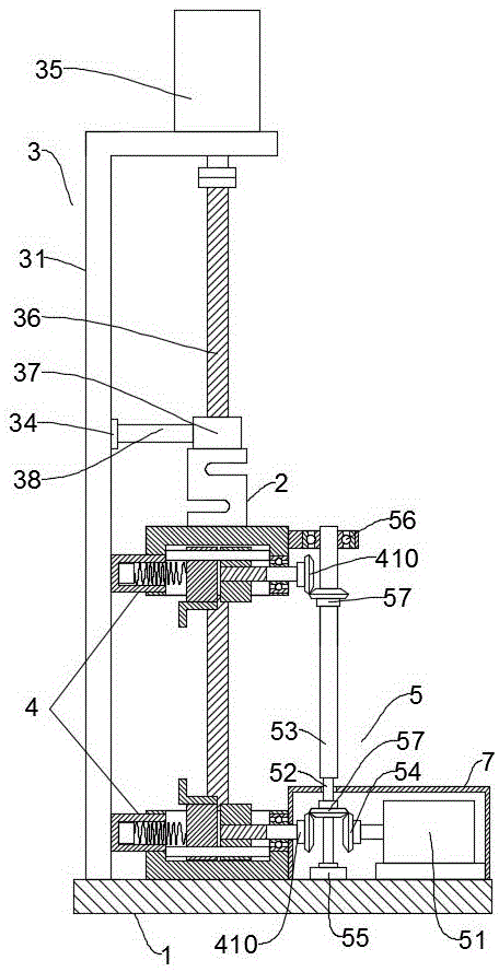
Figure 202021531812

The utility model discloses a cable tensile strength reliability detection device, which comprises a worktable, an S-shaped tension sensor, a stretching mechanism and two clamping mechanisms arranged up and down opposite to each other, and further comprises a clamping mechanism for driving the clamping mechanism to clamp the cable clamping drive mechanism. The utility model can pre-clamp the cable to be detected on the clamping mechanism of the upper and lower layers by turning the L-shaped dial, and then drive the clamping mechanism to completely clamp the cable through the clamping driving mechanism, which is convenient for the tensile strength of the cable. After testing, the clamping mechanism can be reset by the system control, which is convenient for testing the tensile strength of the next cable; the operator does not need to manually screw the screw to fix the cable, and the process of clamping and loosening the cable is fast and convenient, which significantly improves the The detection efficiency reduces the labor burden of the staff, and the clamping force is easy to control, and the two ends of the cable are fixed firmly and are not easy to slip.

Figure 202021531812

Description

Cable tensile strength reliability detection device
Technical Field
The utility model relates to a cable check out test set technical field, especially a cable tensile strength reliability detection device.
Background
The tension detection equipment is a tension tester, is used for carrying out mechanical stress application testing for mechanical property tests such as static load, stretching, compression, bending, shearing, tearing, peeling and the like of instruments and equipment aiming at various materials, is suitable for various physical and mechanical property tests of materials such as plastic plates, pipes, profiled bars, plastic films, rubber, electric wires, cables, steel, glass fibers and the like, is material development, is indispensable detection equipment for physical tests, teaching research, quality control and the like, and needs to be used in cable production.
The common tension detection equipment generally uses a screw compression type clamp, an upper screw and a lower screw are required to be manually screwed when each cable is detected, two ends of each cable are respectively fixed on the clamp, when the next cable is detected, the two ends of each cable cannot be simultaneously and quickly fixed by unscrewing the screws manually, time and labor are wasted in the process of clamping and loosening the cables, so that the detection efficiency is low, and particularly when a large number of cables are detected, the detection personnel can bear heavy labor; and the clamping force is not easy to control during manual operation, the clamping force is small, and the two ends of the test cable are difficult to fix and are easy to slip.
SUMMERY OF THE UTILITY MODEL
The utility model aims at solving the problem, a cable tensile strength reliability detection device has been designed.
The technical scheme of the utility model is that the device for detecting the reliability of the tensile strength of the cable comprises a workbench, an S-shaped tension sensor, a stretching mechanism and two clamping mechanisms which are arranged oppositely up and down, the clamping mechanism comprises a clamping seat, a first sliding rod is fixed in the clamping seat, a driving clamping block and a driven clamping block matched with the driving clamping block to clamp a cable are slidably clamped in the clamping seat, the clamping block and the driven clamping block are both slidably mounted on the first sliding rod, a fixing cylinder is fixedly mounted on one side wall of the clamping seat, a pressure spring and a pressure sensor are arranged in the fixing cylinder, the pressure sensor is located at one end, away from the clamping seat, of the fixing cylinder, two ends of the pressure spring are respectively abutted against the pressure sensor and the driven clamping block, a first screw rod is rotatably mounted on the other side wall of the clamping seat through a first bearing, the first screw rod is in threaded connection with the driving clamping block, and the other end of the first screw rod extends out of;
the stretching mechanism comprises a supporting plate vertically and fixedly mounted on the workbench, a second slide bar vertically arranged is mounted on the supporting plate through a fixing seat, a slide block is slidably mounted on the second slide bar, a first stepping motor is mounted at the top of the supporting plate, a second screw rod is mounted at the rotating end of the first stepping motor through a coupler, the lower end of the second screw rod is mounted on the workbench through a second bearing, a nut seat is mounted on the second screw rod in a threaded manner, and the nut seat is connected with the slide block through a connecting rod;
the clamping seat of the lower clamping mechanism is fixedly arranged on the workbench, and the nut seat and the clamping seat of the upper clamping mechanism are respectively connected with two detection ends of the S-shaped tension sensor;
still press from both sides tight actuating mechanism including being used for driving fixture to press from both sides tight cable, press from both sides tight actuating mechanism and include the second step motor, the transmission shaft, the rotary sleeve, the second step motor is installed on the workstation, drive bevel gear is installed to the rotatory end of second step motor, the rotary sleeve suit is on the transmission shaft and with the transmission shaft key-type connection, the transmission shaft passes through the third bearing and installs on the workstation, be fixed with the bearing frame on fixture's the grip slipper above, the rotary sleeve is installed in the bearing frame, all install drive bevel gear on rotary sleeve and the transmission shaft, the drive bevel gear of installation on rotary sleeve and the transmission shaft is connected with the driven bevel gear meshing of fixture below the top respectively, drive bevel gear is connected with the drive bevel gear.
Preferably, an L-shaped shifting plate is mounted on the end face, back to the clamping seat, of the driven clamping block.
Preferably, a protective shell is fixed on the workbench, and a transmission bevel gear installed on the transmission shaft, a driven bevel gear of the clamping mechanism below, the second stepping motor and the driving bevel gear are all located in the protective shell.
Preferably, the transmission shaft is provided with a sliding key, and the inner wall of the rotating sleeve is provided with a sliding groove for the sliding key to slide.
The utility model has the advantages that: an operator manually shifts the L-shaped shifting plate, the cable to be detected is clamped on the clamping mechanisms on the upper surface and the lower surface in advance under the action of the elastic force of the pressure spring, and then the clamping driving mechanism drives the clamping mechanisms to completely clamp the cable, so that the tensile strength of the cable can be conveniently detected; after the detection is finished, the clamping mechanism can be reset under the control of the system, so that the tensile strength of the next cable can be conveniently detected; need not the manual screw rod fixed cable of twisting of operating personnel, the process of pressing from both sides tight and unclamping the cable is swift convenient, has obviously improved detection efficiency, has reduced staff's work operation burden to press from both sides tight dynamics and easily control, the both ends of cable are fixed firmly, are difficult for the slippage.
Drawings
Fig. 1 is a schematic structural diagram of the present invention;
fig. 2 is a rear view of the present invention;
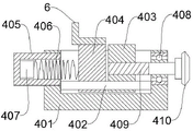
FIG. 3 is a schematic structural view of the clamping mechanism and the L-shaped shifting plate;
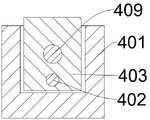
FIG. 4 is a cross-sectional view of the clamping mechanism;
FIG. 5 is a partial schematic view of the drive shaft and rotating sleeve;
in the figure, 1, a workbench; 2. an S-shaped tension sensor; 3. a stretching mechanism; 31. a support plate; 32. a fixed seat; 33. a second slide bar; 34. a slider; 35. a first stepper motor; 36. a second screw; 37. a nut seat; 38. a connecting rod; 39. a second bearing; 4. a clamping mechanism; 401. a clamping seat; 402. a first slide bar; 403. an active clamping block; 404. a driven clamping block; 405. a fixed cylinder; 406. a pressure spring; 407. a pressure sensor; 408. a first bearing; 409. a first screw; 410. a driven bevel gear; 5. a clamping drive mechanism; 51. a second stepping motor; 52. a drive shaft; 53. a rotating sleeve; 54. a drive bevel gear; 55. a third bearing; 56. a bearing seat; 57. a drive bevel gear; 58. a sliding key; 59. a chute; 6. an L-shaped shifting plate; 7. and (4) a protective shell.
Detailed Description
The invention is described in detail below with reference to the accompanying drawings, as shown in fig. 1-5: a cable tensile strength reliability detection device comprises a workbench 1, an S-shaped tension sensor 2, a stretching mechanism 3 and two clamping mechanisms 4 which are arranged in an up-down opposite manner, wherein each clamping mechanism 4 comprises a clamping seat 401, a first slide bar 402 is fixed in each clamping seat 401, a driving clamping block 403 and a driven clamping block 404 which is matched with the driving clamping block 403 to clamp a cable are slidably clamped in each clamping seat 401, each clamping block and the driven clamping block 404 are slidably mounted on the corresponding first slide bar 402, a fixed cylinder 405 is fixedly mounted on one side wall of each clamping seat 401, a pressure spring 406 and a pressure sensor 407 are arranged in each fixed cylinder 405, each pressure sensor 407 is located at one end, far away from the corresponding clamping seat 401, of each fixed cylinder 405, two ends of each pressure spring 406 are respectively abutted against the corresponding pressure sensor 407 and the corresponding driven clamping block 404, a first screw 409 is rotatably mounted on the other side wall of each clamping seat 401 through a first bearing 408, and is, the other end of the first screw 409 extends out of the clamping seat 401 and is provided with a driven bevel gear 410;
the stretching mechanism 3 comprises a supporting plate 31 vertically and fixedly installed on the workbench 1, a second slide rod 33 vertically arranged is installed on the supporting plate 31 through a fixed seat 32, a sliding block 34 is installed on the second slide rod 33 in a sliding mode, the fixed seat 32 is fixed on the supporting plate 31, the fixed seat 32 is provided with an upper portion and a lower portion, two ends of the second slide rod 33 are respectively fixed between the upper fixed seat 32 and the lower fixed seat 32, a first stepping motor 35 is installed at the top of the supporting plate 31, a second screw rod 36 is installed at the rotating end of the first stepping motor 35 through a coupler, the lower end of the second screw rod 36 is installed on the workbench 1 through a second bearing 39, a nut seat 37 is installed on the second screw rod 36 in a threaded mode;
the clamping seat 401 of the lower clamping mechanism 4 is fixedly arranged on the workbench 1, and the nut seat 37 and the clamping seat 401 of the upper clamping mechanism 4 are respectively connected with two detection ends of the S-shaped tension sensor 2;
the cable clamping device further comprises a clamping driving mechanism 5 for driving the clamping mechanism 4 to clamp a cable, the clamping driving mechanism 5 comprises a second stepping motor 51, a transmission shaft 52 and a rotary sleeve 53, the second stepping motor 51 is installed on the workbench 1, a driving bevel gear 54 is installed at the rotating end of the second stepping motor 51, the rotary sleeve 53 is sleeved on the transmission shaft 52 and is in key connection with the transmission shaft 52, the transmission shaft 52 is installed on the workbench 1 through a third bearing 55, a bearing seat 56 is fixed on a clamping seat 401 of the upper clamping mechanism 4, the rotary sleeve 53 is installed in a bearing in the bearing seat 56, the rotating sleeve 53 and the transmission shaft 52 are both provided with a transmission bevel gear 57, the transmission bevel gears 57 arranged on the rotating sleeve 53 and the transmission shaft 52 are respectively meshed and connected with the driven bevel gears 410 of the clamping mechanisms 4 at the upper and lower surfaces, and the driving bevel gear 54 is meshed and connected with the transmission bevel gear 57 arranged on the transmission shaft 52.
Preferably, as shown in fig. 1 to 3, in order to facilitate the shifting of the driven clamping block 404 to pre-clamp the cable, an L-shaped shifting plate 6 is mounted on the end surface of the driven clamping block 404 facing away from the clamping seat 401.
Preferably, in order to prevent a cable or other objects from being involved between the driving bevel gear 57 of the driving shaft 52, the driven bevel gear 410 of the lower clamping mechanism 4, and the driving bevel gear 54, and to protect the second stepping motor 51, the protective housing 7 is fixed to the worktable 1, and the driving bevel gear 57 mounted on the driving shaft 52, the driven bevel gear 410 of the lower clamping mechanism 4, the second stepping motor 51, and the driving bevel gear 54 are all located in the protective housing 7, thereby performing a safety protection function.
Preferably, as shown in fig. 5, in order to realize the key connection of the rotating sleeve 53 and the transmission shaft 52, a sliding key 58 is installed on the transmission shaft 52, and a sliding groove 59 for the sliding key 58 to slide is opened on the inner wall of the rotating sleeve 53.
The working principle of the embodiment is as follows: firstly, pre-clamping a cable to be detected on a lower clamping mechanism 4, specifically, shifting an L-shaped shifting plate of the lower clamping mechanism 4, compressing a pressure spring 406, enabling a driving clamping block 403 to be far away from a driven clamping block 404 so as to keep away the distance for clamping the cable, then placing one end of the cable between the driving clamping block 403 and the driven clamping block 404, loosening the L-shaped shifting plate, enabling the driven clamping block 404 to approach the driving clamping block 403 and clamp the cable under the elastic force action of the pressure spring 406, wherein the clamping force is not very large at the moment but enough to clamp the cable, and avoiding the cable from being separated before the other end of the cable is pre-clamped on the upper clamping mechanism 4;
then, the other end of the cable is clamped on the lower clamping mechanism 4 in advance, and the specific process is the same as that of clamping the cable on the lower clamping mechanism 4; by arranging an industrial personal computer, the first stepping motor 35, the second stepping motor 51, the pressure sensor 407 and the S-shaped tension sensor 2 are electrically connected, when two ends of a cable are pre-clamped on the clamping mechanisms 4 on the upper and lower surfaces, the second stepping motor 51 is started by the industrial personal computer, the second stepping motor 51 drives the lower transmission bevel gear 57 and the transmission shaft 52 to rotate through the driving bevel gear 54, the transmission shaft 52 drives the rotary sleeve 53 and the upper transmission bevel gear 57 to rotate through the sliding key 58, the upper and lower transmission bevel gears 57 respectively drive the upper and lower driven bevel gears 410 and the first screw 409 to rotate, under the guiding and supporting action of the first sliding rod 402, the driving clamping block 403 converts the rotating motion of the first screw 409 into linear motion and moves transversely to the direction of the driven clamping block 404, the driving clamping block 403 pushes the cable and the driven clamping block 404 to move, the pressure spring 406 compresses, the pressure between the driving clamping block 403 and the driven clamping block, the pressure sensor 407 detects the pressure between the driving clamping block 403 and the driven clamping block 404, when the pressure reaches a preset value or controls the second stepping motor 51 to output a preset angular displacement, the second stepping motor 51 stops working, and at the moment, the driving clamping block 403 and the driven clamping block 404 clamp the cable, so that the tensile strength of the cable can be detected;
then, the industrial personal computer controls a second stepping motor 51 to work, the second stepping motor 51 drives a second screw rod 36 to rotate, under the guiding action of a second sliding rod 33, a sliding block 34 and a connecting rod 38, a nut seat 37 rises on the second screw rod 36, the sliding block 34, the connecting rod 38, an S-shaped tension sensor 2 and an upper clamping mechanism 4 rise together with the nut seat 37, a cable is stretched, the S-shaped tension sensor 2 detects tension borne by the cable and sends data to the industrial personal computer, during the process, a sliding key 58 slides in a sliding groove 59, and a rotating sleeve 53 rises relative to a transmission shaft 52;
after the detection is finished, the industrial personal computer controls the first stepping motor 35 and the second stepping motor 51 to rotate reversely, the second stepping motor 51 drives the upper clamping mechanism to reset integrally, the first stepping motor 35 drives the driving clamping block 403 to reset, and the driven clamping block 404 also resets under the action of the elastic force of the pressure spring 406, so that the detected cable can be taken out, the steps can be repeated, and the tensile strength of the next cable can be detected.
Above-mentioned technical scheme has only embodied the utility model discloses technical scheme's preferred technical scheme, some changes that this technical field's technical personnel probably made to some parts wherein have all embodied the utility model discloses a principle belongs to within the protection scope of the utility model.

Claims (4)

1.一种电缆抗拉强度可靠性检测装置,包括工作台(1)、S型拉力传感器(2)、拉伸机构(3)和两个上下相向设置的夹持机构(4),其特征在于:1. A cable tensile strength reliability detection device, comprising a workbench (1), an S-type tension sensor (2), a stretching mechanism (3) and two clamping mechanisms (4) arranged up and down opposite to each other, characterized by: in: 所述夹持机构(4)包括夹持座(401),夹持座(401)内固定有第一滑杆(402),夹持座(401)内滑动卡装有主动夹紧块(403)和与主动夹紧块(403)配合夹持电缆的从动夹紧块(404),夹紧块和从动夹紧块(404)均滑动安装在第一滑杆(402)上,夹持座(401)一侧壁上固定安装有固定筒(405),固定筒(405)内设有压簧(406)和压力传感器(407),压力传感器(407)位于固定筒(405)远离夹持座(401)的一端,压簧(406)两端分别与压力传感器(407)和从动夹紧块(404)抵接,夹持座(401)另一侧壁通过第一轴承(408)转动安装有第一螺杆(409),第一螺杆(409)与主动夹紧块(403)螺纹连接,第一螺杆(409)另一端伸出夹持座(401)且安装有从动锥齿轮(410);The clamping mechanism (4) includes a clamping seat (401), a first sliding rod (402) is fixed in the clamping seat (401), and an active clamping block (403) is slidably clamped in the clamping seat (401). ) and a driven clamping block (404) that cooperates with the active clamping block (403) to clamp the cable, the clamping block and the driven clamping block (404) are both slidably installed on the first sliding rod (402), and the clamp A fixing cylinder (405) is fixedly installed on one side wall of the holder (401), a compression spring (406) and a pressure sensor (407) are arranged in the fixing cylinder (405), and the pressure sensor (407) is located away from the fixing cylinder (405) One end of the clamping seat (401) and both ends of the compression spring (406) are respectively in contact with the pressure sensor (407) and the driven clamping block (404), and the other side wall of the clamping seat (401) passes through the first bearing ( 408) A first screw rod (409) is rotatably installed, the first screw rod (409) is threadedly connected with the active clamping block (403), and the other end of the first screw rod (409) protrudes from the clamping seat (401) and is installed with a driven bevel gear (410); 拉伸机构(3)包括竖直固定安装在工作台(1)上的支撑板(31),支撑板(31)上通过固定座(32)安装有竖直设置的第二滑杆(33),第二滑杆(33)上滑动安装有滑块(34),支撑板(31)顶部安装有第一步进电机(35),第一步进电机(35)旋转端通过联轴器安装有第二螺杆(36),第二螺杆(36)下端通过第二轴承(39)安装在工作台(1)上,第二螺杆(36)上螺纹安装有螺母座(37),螺母座(37)与滑块(34)间通过连接杆(38)连接;The stretching mechanism (3) comprises a support plate (31) vertically and fixedly installed on the worktable (1), and a vertically arranged second sliding rod (33) is installed on the support plate (31) through the fixing seat (32). , a slider (34) is slidably installed on the second sliding rod (33), a first step motor (35) is installed on the top of the support plate (31), and the rotating end of the first step motor (35) is installed through a coupling There is a second screw (36), the lower end of the second screw (36) is mounted on the table (1) through a second bearing (39), and a nut seat (37) is threadedly mounted on the second screw (36), and the nut seat ( 37) is connected with the slider (34) through the connecting rod (38); 下面的夹持机构(4)的夹持座(401)固定安装在工作台(1)上,螺母座(37)、上面的夹持机构(4)的夹持座(401)分别与S型拉力传感器(2)的两个检测端连接;The clamping seat (401) of the lower clamping mechanism (4) is fixedly installed on the workbench (1). The nut seat (37) and the clamping seat (401) of the upper clamping mechanism (4) are respectively the same as the S-type The two detection ends of the tension sensor (2) are connected; 还包括用于驱动夹持机构(4)夹紧电缆的夹紧驱动机构(5),夹紧驱动机构(5)包括第二步进电机(51)、传动轴(52)、旋转套(53),第二步进电机(51)安装在工作台(1)上,第二步进电机(51)旋转端安装有主动锥齿轮(54),旋转套(53)套装在传动轴(52)上且与传动轴(52)键连接,传动轴(52)通过第三轴承(55)安装在工作台(1)上,上面的夹持机构(4)的夹持座(401)上固定有轴承座(56),旋转套(53)安装在轴承座(56)内的轴承中,旋转套(53)和传动轴(52)上均安装有传动锥齿轮(57),旋转套(53)和传动轴(52)上安装的传动锥齿轮(57)分别与上下面的夹持机构(4)的从动锥齿轮(410)啮合连接,主动锥齿轮(54)与传动轴(52)上安装的传动锥齿轮(57)啮合连接。It also includes a clamping driving mechanism (5) for driving the clamping mechanism (4) to clamp the cable, and the clamping driving mechanism (5) includes a second stepping motor (51), a transmission shaft (52), a rotating sleeve (53) ), the second stepping motor (51) is installed on the worktable (1), the rotating end of the second stepping motor (51) is installed with a driving bevel gear (54), and the rotating sleeve (53) is sleeved on the transmission shaft (52) and is keyed to the transmission shaft (52), the transmission shaft (52) is mounted on the worktable (1) through the third bearing (55), and the clamping seat (401) of the upper clamping mechanism (4) is fixed with a The bearing seat (56), the rotating sleeve (53) is installed in the bearing in the bearing seat (56), the rotating sleeve (53) and the transmission shaft (52) are both installed with a transmission bevel gear (57), and the rotating sleeve (53) The transmission bevel gear (57) installed on the transmission shaft (52) is meshed with the driven bevel gear (410) of the upper and lower clamping mechanisms (4) respectively, and the driving bevel gear (54) is connected to the transmission shaft (52). The installed drive bevel gear (57) is meshed. 2.根据权利要求1所述的一种电缆抗拉强度可靠性检测装置,其特征在于,所述从动夹紧块(404)背向夹持座(401)的端面上安装有L型拨板(6)。2 . The cable tensile strength reliability testing device according to claim 1 , wherein an L-shaped dial is installed on the end surface of the driven clamping block ( 404 ) facing away from the clamping seat ( 401 ). 3 . plate (6). 3.根据权利要求1所述的一种电缆抗拉强度可靠性检测装置,其特征在于,所述工作台(1)上固定有防护壳(7),传动轴(52)上安装的传动锥齿轮(57)、下面的夹持机构(4)的从动锥齿轮(410)、第二步进电机(51)和主动锥齿轮(54)均位于防护壳(7)内。3. A cable tensile strength reliability detection device according to claim 1, characterized in that a protective shell (7) is fixed on the worktable (1), and a transmission cone installed on the transmission shaft (52) The gear ( 57 ), the driven bevel gear ( 410 ) of the lower clamping mechanism ( 4 ), the second stepper motor ( 51 ) and the driving bevel gear ( 54 ) are all located in the protective casing ( 7 ). 4.根据权利要求1所述的一种电缆抗拉强度可靠性检测装置,其特征在于,所述传动轴(52)上安装有滑键(58),旋转套(53)内壁上开有供滑键(58)滑动的滑槽(59)。4. A cable tensile strength reliability testing device according to claim 1, characterized in that, a sliding key (58) is installed on the transmission shaft (52), and a power supply is provided on the inner wall of the rotating sleeve (53). The slide key (58) slides the chute (59).
CN202021531812.6U 2020-07-29 2020-07-29 Cable tensile strength reliability testing device Active CN212748519U (en)

Priority Applications (1)

Application Number Priority Date Filing Date Title
CN202021531812.6U CN212748519U (en) 2020-07-29 2020-07-29 Cable tensile strength reliability testing device

Applications Claiming Priority (1)

Application Number Priority Date Filing Date Title
CN202021531812.6U CN212748519U (en) 2020-07-29 2020-07-29 Cable tensile strength reliability testing device

Publications (1)

Publication Number Publication Date
CN212748519U true CN212748519U (en) 2021-03-19

Family

ID=75023962

Family Applications (1)

Application Number Title Priority Date Filing Date
CN202021531812.6U Active CN212748519U (en) 2020-07-29 2020-07-29 Cable tensile strength reliability testing device

Country Status (1)

Country Link
CN (1) CN212748519U (en)

Cited By (9)

* Cited by examiner, † Cited by third party
Publication number Priority date Publication date Assignee Title
CN113252464A (en) * 2021-05-12 2021-08-13 安徽电缆股份有限公司 Tension testing device for heat-insulation type cable for electric power control
CN113533053A (en) * 2021-09-16 2021-10-22 南通恒鑫新材料有限公司 New material tensile strength check out test set
CN113702170A (en) * 2021-10-27 2021-11-26 广东电网有限责任公司佛山供电局 Cable tensile strength detection appliance and method
CN113820201A (en) * 2021-09-10 2021-12-21 国网江苏省电力有限公司建设分公司 Concrete pile foundation external application grounding body tensile resistance detection device and application method thereof
CN114441294A (en) * 2022-02-14 2022-05-06 国网吉林省电力有限公司长春供电公司 Cable tensile strength test device
CN114526986A (en) * 2022-01-14 2022-05-24 江苏瑞恒中显光电科技有限公司 LCM screen pressing and testing integrated tool and pressing and testing method thereof
CN114624094A (en) * 2022-03-01 2022-06-14 苏州君思琦线缆科技有限公司 A detection device for the arbitrariness coefficient of swing amplitude and tension for cable production and processing
CN115753328A (en) * 2022-10-13 2023-03-07 中国建筑西南设计研究院有限公司 Optical storage straight and flexible cable performance testing device
CN115753428A (en) * 2022-11-16 2023-03-07 江苏上上电缆集团有限公司 Intelligent cable insulating layer detection platform

Cited By (13)

* Cited by examiner, † Cited by third party
Publication number Priority date Publication date Assignee Title
CN113252464B (en) * 2021-05-12 2023-11-24 安徽电缆股份有限公司 Tension testing device of heat-insulating cable for electric power control
CN113252464A (en) * 2021-05-12 2021-08-13 安徽电缆股份有限公司 Tension testing device for heat-insulation type cable for electric power control
CN113820201B (en) * 2021-09-10 2023-08-15 国网江苏省电力有限公司建设分公司 Tensile property detection device for concrete pile foundation externally-applied grounding body and application method thereof
CN113820201A (en) * 2021-09-10 2021-12-21 国网江苏省电力有限公司建设分公司 Concrete pile foundation external application grounding body tensile resistance detection device and application method thereof
CN113533053A (en) * 2021-09-16 2021-10-22 南通恒鑫新材料有限公司 New material tensile strength check out test set
CN113533053B (en) * 2021-09-16 2021-11-19 南通恒鑫新材料有限公司 New material tensile strength check out test set
CN113702170A (en) * 2021-10-27 2021-11-26 广东电网有限责任公司佛山供电局 Cable tensile strength detection appliance and method
CN114526986A (en) * 2022-01-14 2022-05-24 江苏瑞恒中显光电科技有限公司 LCM screen pressing and testing integrated tool and pressing and testing method thereof
CN114441294B (en) * 2022-02-14 2022-09-13 国网吉林省电力有限公司长春供电公司 Cable tensile strength test device
CN114441294A (en) * 2022-02-14 2022-05-06 国网吉林省电力有限公司长春供电公司 Cable tensile strength test device
CN114624094A (en) * 2022-03-01 2022-06-14 苏州君思琦线缆科技有限公司 A detection device for the arbitrariness coefficient of swing amplitude and tension for cable production and processing
CN115753328A (en) * 2022-10-13 2023-03-07 中国建筑西南设计研究院有限公司 Optical storage straight and flexible cable performance testing device
CN115753428A (en) * 2022-11-16 2023-03-07 江苏上上电缆集团有限公司 Intelligent cable insulating layer detection platform

Similar Documents

Publication Publication Date Title
CN201218763Y (en) A push-pull test device
CN112345350B (en) Rubber plastic strip stretching ability detection device
CN107228796A (en) A kind of horizontal sliding wedge-shaped clamping device
CN211955025U (en) Concrete detection device
CN115096566B (en) Novel pneumatic program-controlled overload test bench
CN217180295U (en) Strength detection device for combined firework paper tube
CN116858656A (en) Mechanical property detection device capable of adapting to materials in different shapes
CN109201947B (en) Cable bending device
CN222979318U (en) Zinc alloy ductility detection device
CN211477853U (en) Universal material testing machine
CN115950732A (en) New material tensile strength detection device and detection method
CN108375542A (en) A kind of two-way electronic stripping tester of battery back-sheet
CN219777359U (en) Workpiece welding strength testing machine
CN212844717U (en) A power cord tensile test device
CN219694771U (en) Profile tension detection testing machine
CN207858350U (en) A kind of jig being fixedly clamped for shaft coupling
CN218412013U (en) Robot part strength tester
CN217688242U (en) Circuit board test board of variable-frequency speed-regulating integrated machine
CN217349629U (en) Turnover machine
CN213932452U (en) A fast measuring device for backlash of planetary gear reducer
CN213397969U (en) A tensioning machine for bolt testing
CN109604996B (en) A fast grabbing and clamping device for RV reducer
CN212169621U (en) A clamping device for machining
CN224189423U (en) Pressure gauge rapid testing equipment
CN221111582U (en) Two-way threaded bolt processing platform

Legal Events

Date Code Title Description
GR01 Patent grant
GR01 Patent grant
TR01 Transfer of patent right

Effective date of registration: 20231016

Address after: 056900 North of Weisi Road West Section, Manufacturing Equipment Park, Wandi Town, Daming County, Handan City, Hebei Province

Patentee after: Jiaxing Cable Co.,Ltd.

Address before: 056900 northeast corner of the intersection of Yuanzhong street and Funan Road, Daming County, Handan City, Hebei Province

Patentee before: Hebei hangpai Cable Co.,Ltd.

PE01 Entry into force of the registration of the contract for pledge of patent right

Denomination of utility model: Reliability testing device for cable tensile strength

Granted publication date: 20210319

Pledgee: China Postal Savings Bank Co.,Ltd. Daming County Branch

Pledgor: Jiaxing Cable Co.,Ltd.

Registration number: Y2024980017644

PC01 Cancellation of the registration of the contract for pledge of patent right

Granted publication date: 20210319

Pledgee: China Postal Savings Bank Co.,Ltd. Daming County Branch

Pledgor: Jiaxing Cable Co.,Ltd.

Registration number: Y2024980017644

PE01 Entry into force of the registration of the contract for pledge of patent right

Denomination of utility model: Reliability testing device for cable tensile strength

Granted publication date: 20210319

Pledgee: China Postal Savings Bank Co.,Ltd. Daming County Branch

Pledgor: Jiaxing Cable Co.,Ltd.

Registration number: Y2026980000799