CN212743500U - Strutting arrangement is used in building engineering construction - Google Patents
Strutting arrangement is used in building engineering construction Download PDFInfo
- Publication number
- CN212743500U CN212743500U CN202021525766.9U CN202021525766U CN212743500U CN 212743500 U CN212743500 U CN 212743500U CN 202021525766 U CN202021525766 U CN 202021525766U CN 212743500 U CN212743500 U CN 212743500U
- Authority
- CN
- China
- Prior art keywords
- fixedly connected
- stand
- slide bar
- building engineering
- lead screw
- Prior art date
- Legal status (The legal status is an assumption and is not a legal conclusion. Google has not performed a legal analysis and makes no representation as to the accuracy of the status listed.)
- Expired - Fee Related
Links
- 238000010276 construction Methods 0.000 title claims abstract description 18
- 238000001125 extrusion Methods 0.000 claims description 13
- 210000000078 claw Anatomy 0.000 description 6
- 238000005381 potential energy Methods 0.000 description 3
- 229910000831 Steel Inorganic materials 0.000 description 2
- 239000010959 steel Substances 0.000 description 2
- 238000009435 building construction Methods 0.000 description 1
- 230000000694 effects Effects 0.000 description 1
- 238000009434 installation Methods 0.000 description 1
- 238000006467 substitution reaction Methods 0.000 description 1
Images

Landscapes
- Forms Removed On Construction Sites Or Auxiliary Members Thereof (AREA)
Abstract
The utility model discloses a strutting arrangement is used in building engineering construction, which comprises a column, the bottom fixedly connected with bracing piece of stand, the bottom fixedly connected with base of bracing piece, the top both sides wall fixedly connected with stopper of stand, stopper sliding connection has the slide bar, the top fixedly connected with adjusting device of slide bar, adjusting device's top fixedly connected with bracket, the equidistant draw-in groove that is provided with in both sides of stand, the utility model relates to a building engineering technical field. This strutting arrangement for building engineering construction has reached stand, bracing piece, base, stopper, slide bar, adjusting device, bracket, draw-in groove and stop device and has constituteed a whole, and overall structure is convenient for adjust, makes things convenient for the staff to carry out quick adjustment according to the on-the-spot condition, supports the building, improves overall stability, facilitates the use, satisfies user demand's purpose.
Description
Technical Field
The utility model relates to a building engineering field, more specifically say, relate to a strutting arrangement for building engineering construction.
Background
The building engineering refers to an engineering entity formed by the construction of various building constructions and their auxiliary facilities and the installation of lines, pipelines and equipment matched with them, in which various supporting devices are needed to assist constructors. At present, current strutting arrangement for building engineering construction, single structure adopts plank or steel pipe to make usually, and overall structure is fixed relatively, is difficult for adjusting, when carrying out the use, needs the staff to build according to the on-the-spot condition, wastes time and energy, can't satisfy the user demand.
SUMMERY OF THE UTILITY MODEL
1. Technical problem to be solved
To the current strutting arrangement for building engineering construction that exists among the prior art, single structure adopts plank or steel pipe to make usually, and overall structure is relatively fixed, is difficult for adjusting, when using, needs the staff to build according to the on-the-spot condition, wastes time and energy, can't satisfy the problem of user demand, the utility model aims to provide a strutting arrangement for building engineering construction, it can realize stand, bracing piece, base, stopper, slide bar, adjusting device, bracket, draw-in groove and stop device and constitute a whole, and overall structure is convenient for adjust, makes things convenient for the staff to adjust according to the on-the-spot condition, supports the building fast, improves overall stability, facilitates the use, satisfies the user demand.
2. Technical scheme
In order to solve the above problems, the utility model adopts the following technical proposal.
The utility model provides a strutting arrangement for building engineering construction, includes the stand, the bottom fixedly connected with bracing piece of stand, the bottom fixedly connected with base of bracing piece, the top both sides wall fixedly connected with stopper of stand, stopper sliding connection has the slide bar, the top fixedly connected with adjusting device of slide bar, adjusting device's top fixedly connected with bracket, the both sides equidistant draw-in groove that is provided with of stand, the bottom fixedly connected with stop device of slide bar, stop device and draw-in groove joint.
Preferably, adjusting device includes the connecting block, the top fixed connection of connecting block and slide bar, the positive pole is led to the top fixedly connected with of connecting block, the top fixedly connected with fixed plate of leading the positive pole, the bottom of fixed plate is rotated and is connected with the rotation lead screw, the bottom fixedly connected with turning block of rotation lead screw, it has lead screw slider to rotate lead screw threaded connection, lead screw slider and lead positive pole sliding connection, the top fixedly connected with ejector pin of lead screw slider, ejector pin and fixed plate sliding connection, the top and the bracket fixed connection of ejector pin.
Preferably, stop device includes the stripper bar, the bottom sliding connection of stripper bar and slide bar, the one end fixedly connected with dog of stand is kept away from to the stripper bar, the fixed surface of dog is connected with the pull ring, the one end fixedly connected with jack catch of dog is kept away from to the stripper bar, jack catch and draw-in groove joint, the lateral wall fixedly connected with supporting spring of jack catch, supporting spring cup joints with the stripper bar, the jack catch is connected with the draw-in groove through supporting spring.
Preferably, the number of the support rods is three, and the support rods are distributed at equal angles.
3. Advantageous effects
Compared with the prior art, the utility model has the advantages of: the device is characterized in that the device comprises a stand column, a support rod, a base, a limiting block, a sliding rod, an adjusting device, a bracket, a clamping groove and a limiting device, the integral structure is convenient to adjust, workers can conveniently and rapidly adjust according to field conditions to support a building, the integral stability is improved, the adjusting device is arranged to facilitate fine adjustment of the bracket, a rotating block is rotated to drive a rotating lead screw to rotate, a lead screw slider is driven to move, a push rod is driven to move, the height of the bracket is adjusted, the use is convenient, the limiting device is arranged to facilitate rapid adjustment of the integral height, a pull ring is pulled to drive a stop block to move, an extrusion rod is driven to move, the elastic potential energy of a support spring is increased, the limit of the clamping claw and the clamping groove is removed, the position of the sliding rod can be adjusted, the position of the bracket is rapidly adjusted, can fix fast, recycle adjusting device and finely tune, improve the support accuracy, reached stand, bracing piece, base, stopper, slide bar, adjusting device, bracket, draw-in groove and stop device and constitute a whole, overall structure is convenient for adjust, makes things convenient for the staff to carry out quick adjustment according to the on-the-spot condition, supports the building, improves overall stability, facilitates the use, satisfies user demand's purpose.
Drawings
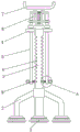
Fig. 1 is a schematic view of the overall structure of the present invention;
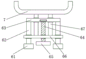
FIG. 2 is a schematic structural view of the adjusting device of the present invention;
fig. 3 is a schematic view of a part of an enlarged structure of fig. 1 according to the present invention.
The reference numbers in the figures illustrate:
1. a column; 2. a support bar; 3. a base; 4. a limiting block; 5. a slide bar; 6. an adjustment device; 61. connecting blocks; 62. a guide rod; 63. a fixing plate; 64. rotating the screw rod; 65. rotating the block; 66. a lead screw slider; 67. a top rod; 7. a bracket; 8. a card slot; 9. a limiting device; 91. an extrusion stem; 92. a stopper; 93. a pull ring; 94. a claw; 95. supporting the spring.
Detailed Description
The drawings in the embodiments of the present invention will be combined; the technical scheme in the embodiment of the utility model is clearly and completely described; obviously; the described embodiments are only some of the embodiments of the present invention; rather than all embodiments. Based on the embodiment of the utility model; all other embodiments obtained by a person skilled in the art without making any inventive step; all belong to the protection scope of the utility model.
Example 1:
referring to fig. 1-3, the present invention provides a technical solution: the utility model provides a strutting arrangement for building engineering construction, including stand 1, the bottom fixedly connected with bracing piece 2 of stand 1, the bottom fixedly connected with base 3 of bracing piece 2, the top both sides wall fixedly connected with stopper 4 of stand 1, stopper 4 sliding connection has slide bar 5, the top fixedly connected with adjusting device 6 of slide bar 5, adjusting device 6's top fixedly connected with bracket 7, the equidistant draw-in groove 8 that is provided with in both sides of stand 1, the bottom fixedly connected with stop device 9 of slide bar 5, stop device 9 and draw-in groove 8 joint. Stand 1, bracing piece 2, base 3, stopper 4, slide bar 5, adjusting device 6, bracket 7, draw-in groove 8 and stop device 9 constitute a whole, and overall structure is convenient for adjust, makes things convenient for the staff to carry out quick adjustment according to the on-the-spot condition, supports the building, improves overall stability.
Example 2:
referring to fig. 2, a supporting device for building engineering construction is substantially the same as that in embodiment 1, and further, the adjusting device 6 includes a connecting block 61, the connecting block 61 is fixedly connected to the top of the sliding rod 5, the top of the connecting block 61 is fixedly connected to a guiding rod 62, the top of the guiding rod 62 is fixedly connected to a fixing plate 63, the bottom of the fixing plate 63 is rotatably connected to a rotating lead screw 64, the bottom of the rotating lead screw 64 is fixedly connected to a rotating block 65, the rotating lead screw 64 is in threaded connection with a lead screw slider 66, the lead screw slider 66 is slidably connected to the guiding rod 62, the top of the lead screw slider 66 is fixedly connected to a top rod 67, the top rod 67 is slidably connected to the fixing plate 63, and the top of the top rod. The adjusting device 6 is arranged, so that fine adjustment of the bracket 7 is facilitated, the rotating block 65 is rotated to drive the rotating lead screw 64 to rotate, the lead screw sliding block 66 is driven to move, the ejector rod 67 is driven to move, the height of the bracket 7 is adjusted, and the use is facilitated.
Example 3:
referring to fig. 3, a supporting device for building engineering construction is substantially the same as embodiment 1, and further, the limiting device 9 includes an extrusion rod 91, the extrusion rod 91 is slidably connected to the bottom of the sliding rod 5, a stopper 92 is fixedly connected to one end of the extrusion rod 91 far from the upright post 1, a pull ring 93 is fixedly connected to the surface of the stopper 92, a claw 94 is fixedly connected to one end of the extrusion rod 91 far from the stopper 92, the claw 94 is clamped with the slot 8, a supporting spring 95 is fixedly connected to a side wall of the claw 94, the supporting spring 95 is sleeved with the extrusion rod 91, and the claw 94 is connected to the slot 8 through the supporting spring 95. Set up stop device 9, be convenient for the holistic height of rapid adjustment, pulling pull ring 93, drive the motion of dog 92, drive the motion of extrusion stem 91, increase supporting spring 95's elastic potential energy, remove the restriction of jack catch 94 and draw-in groove 8, can adjust the position of slide bar 5, and then the position of rapid adjustment bracket 7, loosen pull ring 93, supporting spring 95 elastic potential energy turns into kinetic energy, drive jack catch 94 and draw-in groove 8 and carry out the joint, can fix fast, recycle adjusting device 6 and finely tune, improve the support accuracy.
Example 4:
referring to fig. 1, a supporting device for construction of a building engineering is substantially the same as the embodiment 1, and further, the number of the supporting rods 2 is three, and the supporting rods 2 are distributed at equal angles. Set up three bracing piece 2, improve overall stability.
The above; is only a preferred embodiment of the present invention; however, the scope of protection of the present invention is not limited thereto; any person skilled in the art is within the technical scope of the present disclosure; according to the technical scheme of the utility model and the improvement conception, equivalent substitution or change is carried out; are all covered by the protection scope of the utility model.
Claims (4)
1. The utility model provides a strutting arrangement for building engineering construction, includes stand (1), its characterized in that: the utility model discloses a support column for the automobile seat, including the bottom fixedly connected with bracing piece (2) of stand (1), the bottom fixedly connected with base (3) of bracing piece (2), the top both sides wall fixedly connected with stopper (4) of stand (1), stopper (4) sliding connection has slide bar (5), the top fixedly connected with adjusting device (6) of slide bar (5), the top fixedly connected with bracket (7) of adjusting device (6), the both sides of stand (1) are equidistant to be provided with draw-in groove (8), the bottom fixedly connected with stop device (9) of slide bar (5), stop device (9) and draw-in groove (8) joint.
2. The supporting device for construction of building engineering according to claim 1, wherein: adjusting device (6) include connecting block (61), the top fixed connection of connecting block (61) and slide bar (5), positive pole (62) are led to the top fixedly connected with of connecting block (61), lead top fixedly connected with fixed plate (63) of positive pole (62), the bottom of fixed plate (63) is rotated and is connected with rotation lead screw (64), the bottom fixedly connected with turning block (65) of rotation lead screw (64), it has lead screw slider (66) to rotate lead screw (64) threaded connection, lead screw slider (66) and lead positive pole (62) sliding connection, the top fixedly connected with ejector pin (67) of lead screw slider (66), ejector pin (67) and fixed plate (63) sliding connection, the top and bracket (7) fixed connection of ejector pin (67).
3. The supporting device for construction of building engineering according to claim 1, wherein: stop device (9) are including extrusion stem (91), extrusion stem (91) and the bottom sliding connection of slide bar (5), the one end fixedly connected with dog (92) of stand (1) are kept away from in extrusion stem (91), the fixed surface of dog (92) is connected with pull ring (93), one end fixedly connected with jack catch (94) of dog (92) are kept away from in extrusion stem (91), jack catch (94) and draw-in groove (8) joint, the lateral wall fixedly connected with supporting spring (95) of jack catch (94), supporting spring (95) cup joint with extrusion stem (91), jack catch (94) are connected with draw-in groove (8) through supporting spring (95).
4. The supporting device for construction of building engineering according to claim 1, wherein: the number of the support rods (2) is three, and the support rods (2) are distributed at equal angles.
Priority Applications (1)
| Application Number | Priority Date | Filing Date | Title |
|---|---|---|---|
| CN202021525766.9U CN212743500U (en) | 2020-07-29 | 2020-07-29 | Strutting arrangement is used in building engineering construction |
Applications Claiming Priority (1)
| Application Number | Priority Date | Filing Date | Title |
|---|---|---|---|
| CN202021525766.9U CN212743500U (en) | 2020-07-29 | 2020-07-29 | Strutting arrangement is used in building engineering construction |
Publications (1)
| Publication Number | Publication Date |
|---|---|
| CN212743500U true CN212743500U (en) | 2021-03-19 |
Family
ID=75024594
Family Applications (1)
| Application Number | Title | Priority Date | Filing Date |
|---|---|---|---|
| CN202021525766.9U Expired - Fee Related CN212743500U (en) | 2020-07-29 | 2020-07-29 | Strutting arrangement is used in building engineering construction |
Country Status (1)
| Country | Link |
|---|---|
| CN (1) | CN212743500U (en) |
Cited By (3)
| Publication number | Priority date | Publication date | Assignee | Title |
|---|---|---|---|---|
| CN114809715A (en) * | 2022-04-23 | 2022-07-29 | 中国五冶集团有限公司 | An assembled laminated board support device |
| CN114856183A (en) * | 2022-05-08 | 2022-08-05 | 陈彩盛 | Can prevent crooked template stable support structure for building cement pouring |
| CN116856757A (en) * | 2023-06-12 | 2023-10-10 | 中国核工业华兴建设有限公司 | Quick erection supporting structure of building engineering construction template |
-
2020
- 2020-07-29 CN CN202021525766.9U patent/CN212743500U/en not_active Expired - Fee Related
Cited By (6)
| Publication number | Priority date | Publication date | Assignee | Title |
|---|---|---|---|---|
| CN114809715A (en) * | 2022-04-23 | 2022-07-29 | 中国五冶集团有限公司 | An assembled laminated board support device |
| CN114809715B (en) * | 2022-04-23 | 2023-08-25 | 中国五冶集团有限公司 | An assembled laminated plate support device |
| CN114856183A (en) * | 2022-05-08 | 2022-08-05 | 陈彩盛 | Can prevent crooked template stable support structure for building cement pouring |
| CN114856183B (en) * | 2022-05-08 | 2023-10-31 | 西安高科新达混凝土有限责任公司 | Building cement is template stable support structure for watering that can prevent crooked |
| CN116856757A (en) * | 2023-06-12 | 2023-10-10 | 中国核工业华兴建设有限公司 | Quick erection supporting structure of building engineering construction template |
| CN116856757B (en) * | 2023-06-12 | 2025-11-14 | 中国核工业华兴建设有限公司 | A rapid erection support structure for construction formwork in building engineering |
Similar Documents
| Publication | Publication Date | Title |
|---|---|---|
| CN210105345U (en) | Large-scale steel structure mounting equipment | |
| CN111998824B (en) | Self-suction type positioning measurement auxiliary equipment and use method | |
| CN221004591U (en) | Survey device fixed bolster is used in urban and rural planning | |
| CN210147884U (en) | Pipe fixing device convenient to adjust fixed height | |
| CN220970830U (en) | Electric drill with measurement function | |
| CN219187370U (en) | Environment-friendly furniture electrostatic paint spraying auxiliary device | |
| CN219138326U (en) | Automatic positioning and fastening device for jacking of frame body | |
| CN215908721U (en) | Spirit level for constructional engineering construction measurement | |
| CN217637271U (en) | Geological disaster deep displacement monitoring device | |
| CN217093607U (en) | Test tube fixing device for student experiments | |
| CN205904213U (en) | Oil pipe washs bracket | |
| CN212773638U (en) | Strutting arrangement for building engineering | |
| CN213041192U (en) | Measuring tool for building engineering management | |
| CN217054349U (en) | Concrete forming template convenient to build | |
| CN213749126U (en) | Wind resistance experiment device for steel bridge | |
| CN221078843U (en) | High-voltage insulation test device | |
| CN213710652U (en) | A construction safety management fence | |
| CN215097734U (en) | Pipe fitting placer is used in civil engineering construction | |
| CN213543617U (en) | Building engineering cost on-site mapping device based on BIM | |
| CN207145923U (en) | One kind is used for network equipment mounting bracket | |
| CN215107366U (en) | Foam concrete filling device for building construction | |
| CN216590547U (en) | Pipeline positioning support for water supply and drainage engineering | |
| CN220870471U (en) | Engineering measuring device | |
| CN211145856U (en) | Surveying and mapping device convenient to angle modulation | |
| CN216668740U (en) | Building engineering traffic has straightness detection device that hangs down of stable knot structure |
Legal Events
| Date | Code | Title | Description |
|---|---|---|---|
| GR01 | Patent grant | ||
| GR01 | Patent grant | ||
| CF01 | Termination of patent right due to non-payment of annual fee | ||
| CF01 | Termination of patent right due to non-payment of annual fee |
Granted publication date: 20210319 |