CN212733559U - Non ferrous metal calendering device - Google Patents
Non ferrous metal calendering device Download PDFInfo
- Publication number
- CN212733559U CN212733559U CN202120220723.8U CN202120220723U CN212733559U CN 212733559 U CN212733559 U CN 212733559U CN 202120220723 U CN202120220723 U CN 202120220723U CN 212733559 U CN212733559 U CN 212733559U
- Authority
- CN
- China
- Prior art keywords
- device body
- cooling plate
- plate
- side wall
- ferrous metal
- Prior art date
- Legal status (The legal status is an assumption and is not a legal conclusion. Google has not performed a legal analysis and makes no representation as to the accuracy of the status listed.)
- Expired - Fee Related
Links
- 238000003490 calendering Methods 0.000 title claims abstract description 32
- CWYNVVGOOAEACU-UHFFFAOYSA-N Fe2+ Chemical compound [Fe+2] CWYNVVGOOAEACU-UHFFFAOYSA-N 0.000 title claims abstract description 28
- 239000002184 metal Substances 0.000 title claims abstract description 18
- 229910052751 metal Inorganic materials 0.000 title claims abstract description 18
- 238000001816 cooling Methods 0.000 claims abstract description 29
- 230000006835 compression Effects 0.000 claims abstract description 18
- 238000007906 compression Methods 0.000 claims abstract description 18
- 238000005096 rolling process Methods 0.000 claims description 39
- 238000003825 pressing Methods 0.000 claims description 16
- 230000003014 reinforcing effect Effects 0.000 claims description 4
- 238000007599 discharging Methods 0.000 claims description 3
- 238000009434 installation Methods 0.000 claims description 3
- 230000002146 bilateral effect Effects 0.000 claims 1
- 239000007769 metal material Substances 0.000 description 12
- 238000004519 manufacturing process Methods 0.000 description 3
- 239000000463 material Substances 0.000 description 3
- -1 ferrous metals Chemical class 0.000 description 1
- 238000012423 maintenance Methods 0.000 description 1
- 238000000034 method Methods 0.000 description 1
- 230000008092 positive effect Effects 0.000 description 1
- 230000007115 recruitment Effects 0.000 description 1
- 230000001629 suppression Effects 0.000 description 1
Images


Landscapes
- Casting Or Compression Moulding Of Plastics Or The Like (AREA)
Abstract
The utility model provides a non ferrous metal calendering device, including first backup pad, telescopic support leg and calendering device body, the vertical a plurality of telescopic support legs of installing in first backup pad bottom, a calendering device body is installed at first backup pad top, the calendering device body is provided with a feed inlet on cuboid box column structure and its one of them lateral wall that a lateral wall opened the state, the suit is provided with the compression roller in the second pivot, it is located down directly over the compression roller to go up the compression roller, the cooling plate is installed down to calendering device body inboard bottom, the inboard vertical lifter of installing downwards in calendering device body top, lifter bottom free end level safety is equipped with one and goes up the cooling plate, it is located down the cooling plate directly over to go up the cooling plate, it is located between discharge gate and the mounting bracket with cooling plate down to go up the cooling plate. The utility model discloses make the user become more convenient and high-efficient to the calendering processing of non ferrous metal, can realize calendering processing to the non ferrous metal that different thickness required.
Description
Technical Field
The utility model belongs to non ferrous metal production facility field especially relates to a non ferrous metal calendering device.
Background
In the processing of non-ferrous metal materials, a rolling operation for processing the metal materials into a flat shape is often designed, and non-ferrous metal rolling refers to that thick materials made of non-ferrous metals are processed into a thinner sheet structure through the rolling operation.
At present non ferrous metal rolling equipment often only is used for the calendering of a thickness product, and when needing to process non ferrous metal material into different specification thickness, often need adjust the equipment clearance, and same equipment is difficult to realize the operation of rolling into variable thickness thin slice with same material, simultaneously when rolling the operation, often aim at the position of waiting to roll the rolling equipment with thick material through manual mode, however this kind of mode needs a large amount of manual operation to proofread and correct on the one hand, the recruitment cost has not only been increased, and because improper operation can cause the suppression damage of product, cause economic loss.
Disclosure of Invention
The to-be-solved problem of the utility model is to provide a non ferrous metal calendering device, especially be fit for the user and carry out the calendering processing to non ferrous metal material, and can adjust calendering thickness.
In order to solve the technical problem, the utility model discloses a technical scheme is: the non-ferrous metal rolling device comprises a first supporting plate, a plurality of telescopic supporting legs and a rolling device body, wherein the bottom of the first supporting plate is vertically provided with the plurality of telescopic supporting legs, the top of the first supporting plate is provided with the rolling device body, the rolling device body is of a cuboid box-shaped structure with one side wall in an open state, a feeding hole is formed in one side wall of the rolling device body, a discharging hole is symmetrically formed in one side wall of the rolling device body opposite to the feeding hole, second sliding grooves are symmetrically and vertically formed in two sides of the inner side wall of the rolling device body provided with the feeding hole, second sliding blocks are symmetrically and slidably arranged on the second sliding grooves in two sides, a pressing plate is horizontally arranged between the second sliding blocks in two sides, a fixing plate is horizontally arranged on the inner side wall of the rolling device body above the feeding hole, a second lower pressing rod is vertically arranged at the center, a second support plate is horizontally arranged at the bottom of the feed inlet and positioned on the inner side wall of the calendaring device body, a limiting groove is horizontally arranged on the side wall of the pressure plate, two clamping blocks are arranged on the limiting groove in a sliding manner, a limiting plate is vertically arranged at the bottom of each clamping block, a base is arranged at the bottom of the inner side of the calendaring device body, a support frame is arranged on the upper surface of the base, a first rotating shaft is horizontally arranged on the support frame, a lower press roll is sleeved on the first rotating shaft, a mounting frame is arranged on the inner wall of the top of the calendaring device body, the mounting frame is positioned right above the support frame, first sliding grooves are symmetrically and vertically arranged on the inner sides of the two side walls of the mounting frame, first sliding blocks are respectively arranged on the first sliding grooves on the two sides in a sliding manner, a mounting seat is horizontally arranged between the, horizontal installation has a second pivot between two inside walls of mount pad, and the suit is provided with the compression roller in the second pivot, goes up the compression roller and is located the compression roller down directly over, and the cooling plate is installed down to calendering device body inboard bottom, and the vertical lifter of installing downwards in calendering device body top inboard, the cooling plate is equipped with in lifter bottom free end horizontal installation, goes up the cooling plate and is located the cooling plate down directly over, goes up the cooling plate and is located between discharge gate and the mounting bracket with cooling plate down.
Furthermore, a reinforcing rib is arranged between the bottom of the second supporting plate and the inner side wall of the calendering device body.
Furthermore, the bottom surface of the pressing plate is provided with an elastic pad.
In the use, the user will treat the non ferrous metal material of processing and put into from the feed inlet, and the user presses the clamp plate at non ferrous metal material upper surface this moment, and then the user fixes both sides about non ferrous metal material through the limiting plate, and then the user presses down the compression roller cooperation through first depression bar and rolls down the compression roller, then cools off the processing through last cooling plate and lower cooling plate to the non ferrous metal material after rolling, then discharges through the discharge gate.
The utility model has the advantages and positive effects that: by adopting the technical scheme, the rolling treatment of the non-ferrous metal by a user becomes more convenient and efficient, the rolling treatment of the non-ferrous metal with different thickness requirements can be realized, the accurate rolling can be effectively realized, and the production quality of products is ensured; just the utility model has the advantages of simple structure, easy maintenance, low processing cost, high production efficiency, etc.
Drawings
FIG. 1 is a schematic side view of a portion of the internal structure of the present invention;
FIG. 2 is a schematic structural view of a lower compression roller portion of the present invention;
FIG. 3 is a schematic structural view of the upper roll part of the present invention;
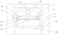
fig. 4 is a schematic view of the inner structure of the feed inlet part of the present invention.
In the figure:
1. first supporting plate 2, telescopic supporting leg 3 and calendering device body
4. Feed inlet 5, discharge gate 6, mounting bracket
7. Support frame 8, lifter 9, upper cooling plate
10. Lower cooling plate 11, base 12, first rotating shaft
13. Lower press roll 14, first chute 15 and first lower press rod
16. First slide block 17, mounting seat 18 and second rotating shaft
19. Upper press roller 20, second sliding groove 21 and limit groove
22. A second slide block 23, a fixed plate 24 and a second press rod
25. Pressing plate 26, elastic pad 27 and second supporting plate
28. The reinforcing rib 29, the fixture block 30 and the limiting plate.
Detailed Description
As shown in figures 1-4, the utility model relates to a non-ferrous metal rolling device, which comprises a first supporting plate 1, a plurality of telescopic supporting legs 2 and a rolling device body 3, wherein the bottom of the first supporting plate 1 is vertically provided with a plurality of telescopic supporting legs 2, the top of the first supporting plate 1 is provided with a rolling device body 3, the rolling device body 3 is a cuboid box-shaped structure with an opened side wall, one side wall of the rolling device body 3 is provided with a feeding hole 4, one side wall of the rolling device body 3 opposite to the feeding hole 4 is symmetrically provided with a discharging hole 5, two sides of the inner side wall of the rolling device body 3 provided with the feeding hole 4 are symmetrically and vertically provided with second chutes 20, two sides of the second chutes 20 are symmetrically provided with second slide blocks 22 in a sliding way, a press plate 25 is horizontally arranged between the second slide blocks 22 at two sides, and a fixed plate 23, a second lower pressure rod 24 is vertically arranged at the center of the bottom of the fixing plate 23, the free end of the bottom of the second lower pressure rod 24 is arranged at the center of the upper surface of the pressure plate 25, a second support plate 27 is horizontally arranged at the bottom of the feed inlet 4 and on the inner side wall of the calendaring device body 3, a limit groove 21 is horizontally arranged on the side wall of the pressure plate 25, two fixture blocks 29 are slidably arranged on the limit groove 21, a limit plate 30 is vertically arranged at the bottom of each fixture block 29, a base 11 is arranged at the bottom of the inner side of the calendaring device body 3, a support frame 7 is arranged on the upper surface of the base 11, a first rotating shaft 12 is horizontally arranged on the support frame 7, a lower pressure roller 13 is sleeved on the first rotating shaft 12, a mounting frame 6 is arranged on the inner wall of the top of the calendaring device body 3, the mounting frame 6 is positioned right above the support frame 7, first sliding, a mounting seat 17 is horizontally mounted between first sliders 16 on two sides, a first lower pressing rod 15 is vertically mounted downwards at the center of the top of the inner side of a mounting frame 6, the free end of the bottom of the first lower pressing rod 15 is mounted at the center of the top of the mounting seat 17, a second rotating shaft 18 is horizontally mounted between the two inner side walls of the mounting seat 17, an upper pressing roller 19 is arranged on the second rotating shaft 18 in a sleeved mode, the upper pressing roller 19 is located right above the lower pressing roller 13, a cooling plate 10 is mounted at the bottom of the inner side of a rolling device body 3, a lifting rod 8 is vertically mounted downwards at the top of the rolling device body 3, an upper cooling plate 9 is horizontally mounted at the free end of the bottom of the lifting rod 8, the upper cooling plate 9 is located right above the lower cooling plate 10, and the upper cooling plate 9 and the lower.
Further, a reinforcing rib 28 is installed between the bottom of the second supporting plate 27 and the inner side wall of the rolling device body 3.
Further, the pressing plate 25 is provided with an elastic pad 26 on the bottom surface.
In the use, the user will treat the non ferrous metal material of processing and put into from feed inlet 4, and the user presses clamp plate 25 at non ferrous metal material upper surface this moment, and then the user fixes non ferrous metal material's left and right sides through limiting plate 30, and then the user presses down compression roller 19 cooperation lower compression roller 13 through first lower compression bar 15 and rolls, then cools off the processing through last cooling plate 9 and lower cooling plate 10 to the non ferrous metal material after rolling, then discharges through discharge gate 5.
While one embodiment of the present invention has been described in detail, the description is only a preferred embodiment of the present invention, and should not be considered as limiting the scope of the present invention. All the equivalent changes and improvements made according to the application scope of the present invention should still fall within the patent coverage of the present invention.
Claims (3)
1. The utility model provides a non ferrous metal calendering device which characterized in that: the device comprises a first supporting plate (1), a plurality of telescopic supporting legs (2) and a rolling device body (3), wherein the telescopic supporting legs (2) are vertically arranged at the bottom of the first supporting plate (1), one rolling device body (3) is arranged at the top of the first supporting plate (1), the rolling device body (3) is a cuboid box-shaped structure with a side wall opened, a feeding hole (4) is formed in one side wall of the rolling device body, a discharging hole (5) is symmetrically arranged on one side wall of the rolling device body (3) opposite to the feeding hole (4), second sliding grooves (20) are vertically arranged in bilateral symmetry on the inner side wall of the rolling device body (3) with the feeding hole (4), second sliding blocks (22) are symmetrically arranged on the second sliding grooves (20) on two sides, and a pressing plate (25) is horizontally arranged between the second sliding blocks (22) on two sides, the upper horizontal mounting of the inner side wall of the calendering device body (3) above the feed inlet (4) is provided with a fixed plate (23), the center of the bottom of the fixed plate (23) is vertically provided with a second lower pressing rod (24), the free end of the bottom of the second lower pressing rod (24) is mounted at the center of the upper surface of the pressing plate (25), the bottom of the feed inlet (4) is positioned on the upper horizontal mounting of the inner side wall of the calendering device body (3) is provided with a second supporting plate (27), the upper horizontal mounting of the side wall of the pressing plate (25) is provided with a limiting groove (21), the limiting groove (21) is provided with two clamping blocks (29) in a sliding manner, the bottoms of the clamping blocks (29) are respectively and vertically provided with a limiting plate (30), the bottom of the inner side of the calendering device body (3) is provided with a base (, the device is characterized in that a first rotating shaft (12) is horizontally arranged on the support frame (7), a lower compression roller (13) is sleeved on the first rotating shaft (12), a mounting frame (6) is installed on the inner wall of the top of the calendaring device body (3), the mounting frame (6) is located right above the support frame (7), first sliding grooves (14) are vertically installed in the inner side of two side walls of the mounting frame (6) in a symmetrical mode, first sliding blocks (16) are arranged on the first sliding grooves (14) on two sides in a sliding mode, a mounting seat (17) is horizontally installed between the first sliding blocks (16) on two sides, a first lower compression rod (15) is vertically installed downwards in the center of the inner top of the mounting frame (6), the free end of the bottom of the first lower compression rod (15) is installed in the center of the top of the mounting seat (17), a second rotating shaft (18) is horizontally installed between the two, the suit is provided with compression roller (19) on second pivot (18), it is located to go up compression roller (19) directly over compression roller (13) down, calendering device body (3) inboard bottom and installing cooling plate (10) once, calendering device body (3) top inboard is vertical installs down a lifter (8), lifter (8) bottom free end horizontal installation is equipped with one and goes up cooling plate (9), it is located to go up cooling plate (9) directly over cooling plate (10) down, go up cooling plate (9) with cooling plate (10) are located down discharge gate (5) with between mounting bracket (6).
2. A non-ferrous metal rolling apparatus as set forth in claim 1, wherein: and a reinforcing rib (28) is arranged between the bottom of the second supporting plate (27) and the inner side wall of the rolling device body (3).
3. A non-ferrous metal rolling apparatus as set forth in claim 1, wherein: and an elastic pad (26) is arranged on the bottom surface of the pressing plate (25).
Priority Applications (1)
| Application Number | Priority Date | Filing Date | Title |
|---|---|---|---|
| CN202120220723.8U CN212733559U (en) | 2021-01-27 | 2021-01-27 | Non ferrous metal calendering device |
Applications Claiming Priority (1)
| Application Number | Priority Date | Filing Date | Title |
|---|---|---|---|
| CN202120220723.8U CN212733559U (en) | 2021-01-27 | 2021-01-27 | Non ferrous metal calendering device |
Publications (1)
| Publication Number | Publication Date |
|---|---|
| CN212733559U true CN212733559U (en) | 2021-03-19 |
Family
ID=74990425
Family Applications (1)
| Application Number | Title | Priority Date | Filing Date |
|---|---|---|---|
| CN202120220723.8U Expired - Fee Related CN212733559U (en) | 2021-01-27 | 2021-01-27 | Non ferrous metal calendering device |
Country Status (1)
| Country | Link |
|---|---|
| CN (1) | CN212733559U (en) |
Cited By (1)
| Publication number | Priority date | Publication date | Assignee | Title |
|---|---|---|---|---|
| CN117286434A (en) * | 2023-09-14 | 2023-12-26 | 江西金泰合新材料科技有限公司 | A stress relief device and method for non-ferrous metal rolling |
-
2021
- 2021-01-27 CN CN202120220723.8U patent/CN212733559U/en not_active Expired - Fee Related
Cited By (2)
| Publication number | Priority date | Publication date | Assignee | Title |
|---|---|---|---|---|
| CN117286434A (en) * | 2023-09-14 | 2023-12-26 | 江西金泰合新材料科技有限公司 | A stress relief device and method for non-ferrous metal rolling |
| CN117286434B (en) * | 2023-09-14 | 2026-03-27 | 江西金泰合新材料科技有限公司 | A stress relief device and method for non-ferrous metal rolling |
Similar Documents
| Publication | Publication Date | Title |
|---|---|---|
| WO2020237833A1 (en) | Sheet metal sheet stamping forming device | |
| CN210358654U (en) | Automatic material conveying structure of sheet metal part bending die | |
| CN204074961U (en) | A pressing device for a stamping die of an outer panel of an automobile door | |
| CN107571088A (en) | A kind of boring shaping support with waste material splicing of bending handware | |
| CN103029499B (en) | A kind of edge knurling machine | |
| CN112474916A (en) | Metal plate bending die | |
| CN105945100A (en) | Forming device for automobile side skin | |
| CN204074950U (en) | Stamping die for an automobile door outer panel | |
| CN102247996A (en) | Rapid assembly structure for scraper device | |
| CN110420998A (en) | A kind of hot rolled steel plate production technology | |
| CN211965376U (en) | Roller type cold rolling mill | |
| CN215587618U (en) | Stamping part die | |
| CN211305096U (en) | Tapping machine | |
| CN212703874U (en) | Nickel-iron alloy stamping die | |
| CN218835882U (en) | Part negative angle bending device applied to die | |
| CN211071660U (en) | Flange forging and extruding device | |
| CN216369525U (en) | Ball head positioning compression roller and roller changing device | |
| CN217606682U (en) | Iron core frame of laminating machine | |
| CN113083952B (en) | Equipment for manufacturing cold rolled steel bending by high-end equipment | |
| CN216832364U (en) | Rolling device for die steel | |
| CN220574574U (en) | Punch press convenient for quickly fixing workpiece | |
| CN215543932U (en) | High-precision cold rolling mechanism for steel pipe machining | |
| CN218108925U (en) | A mold steel deformation correction device | |
| CN223673929U (en) | Gasket processing loading attachment | |
| CN218254693U (en) | Sheet metal machining table capable of being adapted to sheet metals of different sizes |
Legal Events
| Date | Code | Title | Description |
|---|---|---|---|
| GR01 | Patent grant | ||
| GR01 | Patent grant | ||
| CF01 | Termination of patent right due to non-payment of annual fee |
Granted publication date: 20210319 |
|
| CF01 | Termination of patent right due to non-payment of annual fee |