SUMMERY OF THE UTILITY MODEL
The utility model aims to solve the technical problem that a high-efficient circulation air separator is provided, guarantees the seal of winnowing equipment, and the dust subsides fast, and material light impurity separation is abundant, effectively improves the efficiency and the quality of material selection by winnowing.
In order to solve the above problems, the utility model adopts the following technical proposal:
a high-efficiency circulating air separator comprises a machine body, a circulating air separation channel arranged in the machine body, a feeding box fixedly connected to the lower side part of the machine body, a vibrating feeding mechanism communicated with the feeding box and the circulating air separation channel in the machine body, an impurity settling chamber connected below a circulating air separation chamber, an impurity box connected below the impurity settling chamber, an air-blocking discharging box fixedly connected to the lower end of the impurity box and an air-blocking discharging mechanism connected to the air-blocking discharging box;
the impurity settling chamber adopts a sand-lock cylinder connected between the circulating air duct and the impurity box to form a spiral settling structure.
As a further improvement of the utility model, the circulating winnowing chamber comprises a circulating air duct fixedly connected to the upper part of the machine body, a fan fixedly connected to the side end of the circulating air duct, and an air duct arranged in the machine body and communicated with the feeding box and the circulating air duct;
the air outlet of the fan is communicated with the ventilation duct through the air outlet pipe, and the air inlet of the fan is communicated with the circulating air duct.
As a further improvement of the utility model, the spiral sedimentation structure further comprises an air suction straight pipe positioned in the cyclone cylinder, and the upper port of the air suction straight pipe is fixedly connected to the inner side of the bottom plate of the circulating air duct through a straight pipe flange;
the outer side of the air suction straight pipe is fixedly and spirally connected with a packing auger positioned in the sand-cock cylinder.
As a further improvement of the utility model, the outer diameter of the air suction straight pipe is smaller than the inner diameter of the upper port of the shakelong cylinder, and the bottom of the circulating air duct is fixedly connected with an air deflector; the air deflector is positioned between the outer side wall of the air suction straight pipe and the inner side wall of the upper port of the shakelong cylinder;
the upper port of the ventilation duct is communicated with the sand-cock cylinder through the air deflector.
As a further improvement of the utility model, the air-lock discharging mechanism comprises an air-lock casing, a rotating shaft rotatably mounted in the air-lock casing, and an air-lock impeller fixedly connected to the periphery of the rotating shaft along the axial direction of the rotating shaft;
the number of the wind-blocking impellers is more than four, and the wind-blocking impellers are distributed outside the rotating shaft in an array mode by taking the rotating shaft as a center.
As a further improvement of the utility model, the air-closing discharging mechanism further comprises a speed reducer, wherein a driving shaft of the speed reducer is fixedly connected with the rotating shaft;
a fixed mounting block is fixedly connected to the upper port of the inner side of the air seal device shell, and a brush is fixedly mounted on the fixed mounting block;
the rotating shaft is rotatably connected with the air closer shell through a bearing seat, and a protective cover is fixedly arranged on the outer side of the air closer shell;
the outer end of the rotating shaft is positioned in the protective cover;
the upper port of the air seal device shell is fixedly connected with the lower port of the air seal discharge box through an upper flange;
the lower port of the air closer shell is fixedly connected with an air closer discharge port through a lower flange.
As a further improvement of the utility model, the vibration feeding mechanism comprises a vibration feeding box shell, a material blocking inclined plate fixedly connected to the inner side of the vibration feeding box shell, a material dripping plate positioned below the material blocking inclined plate, an eccentric vibration mechanism arranged at the bottom of the material dripping plate and a suspension rod group connected to the outer sides of the material dripping plate and the machine body;
and the upper port of the shell of the vibration feeding box is connected with the lower port of the feeding box.
As a further improvement of the utility model, the eccentric vibration mechanism comprises a vibration motor fixedly arranged on one side of the shell of the vibration feeding box, a driving shaft rotationally connected to two side plates of the shell of the vibration feeding box through a bearing connecting seat, an eccentric sleeve connected to the driving shaft in a key way, and a vibration support arm sleeved outside the eccentric sleeve through rotation of a ball;
the end part of the vibration support arm is fixedly connected with a support lug which is supported on the bottom surface of the material dripping plate.
As a further improvement of the utility model, two sides of the material dripping plate are fixedly connected with side vertical plates positioned in the shell of the vibration feeding box;
the suspension rod group comprises a fixed connecting plate fixedly arranged on the outer side of the machine body, an upper threaded suspension rod penetrating through the fixed connecting plate, a star-shaped handle connected to the upper portion of the upper threaded suspension rod in a threaded manner and positioned above the fixed connecting plate, a lower threaded suspension rod hinged to the side vertical plate, and a spring part hung and sleeved between the lower end of the upper threaded suspension rod and the upper end of the lower threaded suspension rod.
As a further improvement of the utility model, the lower threaded boom penetrates through the shell of the vibration feeding box, and a sheath cylinder is arranged between the lower threaded boom and the shell of the vibration feeding box; the upper end of the sheath cylinder is fixedly connected with a corrugated protective pipe sleeved outside the lower threaded suspender;
the grain protective pipe is positioned outside the shell of the vibration feeding box.
Adopt the produced beneficial effect of above-mentioned technical scheme to lie in:
the utility model discloses have the spiral and subside the structure, the straight tube that induced drafts and the spiral dust remover of husky ke long cylindric one-tenth that adopt the outside to have the auger, the inertial centrifugal force that leans on rotatory air current combines the friction deceleration to separate impurity promptly, the centrifugal force that this kind of motion made impurity production increases many times than the gravity, therefore efficiency such as dust removal has improved 3-4 times at least about than dust settling chamber dust fall, and simple structure, compactness, low in manufacturing cost, the jam problem in the return air inlet in the dust settling chamber in the traditional structure has been avoided, user's cleaning work has been reduced.
The utility model discloses have the impeller and close wind structure of unloading, this structure passes through the impeller and forms sealedly with the cavity, and the foreign material passes through the impeller rotation and discharges, and the sealing of dust fall part is irrelevant with piling up of material, and this structure is sealed more reliably through the knot part to more can guarantee effective dust fall.
The utility model discloses have vibration feed structure, the flitch of trickling through eccentric mechanism and circulation selection by winnowing is connected, reach the effect of trickling flitch law vibration, when the material stream was through trickling the flitch, can be covered the material through the vibration and drip the flitch width with equipment, and clearance grow between the material granule, guarantee that the granule is abundant through the selection by winnowing, improve separation efficiency, and after circulation wind is equipped with vibration feed system, but this vibration feed structure exclusive use also can use with the microphone set combination, the suitability is more extensive.
Drawings
In order to more clearly illustrate the technical solutions of the embodiments of the present invention, the drawings required for the embodiments or the prior art descriptions will be briefly described below, and it is obvious that the drawings in the following description are only some embodiments of the present invention, and it is obvious for those skilled in the art to obtain other drawings without creative efforts.
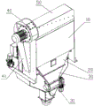
FIG. 1 is a schematic view of an axial angle measurement structure of the present invention;
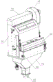
FIG. 2 is a schematic view of another angle measurement structure of the present invention;
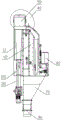
FIG. 3 is a schematic structural view of the circulating air separation channel of the present invention;
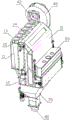
fig. 4 is a schematic structural diagram of the air inlet of the fan of the present invention;
FIG. 5 is a schematic structural view of the straight suction pipe of the present invention;
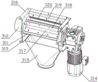
FIG. 6 is a schematic structural view of the air-closing unloading mechanism of the present invention;
fig. 7 is a schematic structural view of the airlock impeller of the present invention;
FIG. 8 is a schematic view of the external structure of the vibrating feeding mechanism of the present invention;
FIG. 9 is a schematic view of the vibrating feeding plate of the present invention;
fig. 10 is a schematic structural view of the suspension bar assembly of the present invention;
fig. 11 is a schematic structural view of the eccentric sleeve and the vibrating arm according to the present invention.
Wherein:
10 machine body, 20 impurity box, 30 air-closed discharge box, 40 fan, 50 circulating air duct, 60 feeding box, 70 discharge box, 80 discharge hole, 90 vibration feeding mechanism, 11 shakelong cylinder, 12 air duct, 13 straight pipe flange, 14 air deflector, 15 air suction straight pipe, 16 packing auger, 31 air-closed discharge mechanism, 311 air-closed device shell, 312 protective cover, 313 air-closed device discharge hole, 314 speed reducer, 315 lower flange, 316 upper flange, 317 rotating shaft, 318 wind-blocking impeller, 319 fixed mounting block, 320 hairbrush, 41 air outlet pipe, 42 fan air inlet, 91 vibration feeding box shell, 92 fixed connecting plate, 93 suspension rod group, 94 bearing connecting seat, 95 vibration motor, 96 material dripping plate, 97 side vertical plate, 98 material blocking inclined plate, 99 vibration support arm, 990 support ear, 931 star-shaped handle, 932 upper thread suspension rod, 933 spring element, 934 lower thread suspension rod, 935 corrugated protection pipe, 936 driving shaft and 937 eccentric sleeve.
Detailed Description
The technical solutions in the embodiments of the present application will be clearly and completely described below with reference to the drawings in the embodiments of the present application, and it is obvious that the described embodiments are only a part of the embodiments of the present application, and not all of the embodiments. The following description of at least one exemplary embodiment is merely illustrative in nature and is in no way intended to limit the application, its application, or uses. All other embodiments, which can be derived by a person skilled in the art from the embodiments given herein without making any creative effort, shall fall within the protection scope of the present application.
It is noted that the terminology used herein is for the purpose of describing particular embodiments only and is not intended to be limiting of example embodiments according to the present application. As used herein, the singular forms "a", "an" and "the" are intended to include the plural forms as well, and it should be understood that when the terms "comprises" and/or "comprising" are used in this specification, they specify the presence of stated features, steps, operations, devices, components, and/or combinations thereof, unless the context clearly indicates otherwise.
It should be noted that: like reference numbers and letters refer to like items in the following figures, and thus, once an item is defined in one figure, further discussion thereof is not required in subsequent figures.
In the description of the present application, it is to be understood that the orientation or positional relationship indicated by the directional terms such as "front, rear, upper, lower, left, right", "lateral, vertical, horizontal" and "top, bottom", etc., are generally based on the orientation or positional relationship shown in the drawings, and are used for convenience of description and simplicity of description only, and in the case of not making a reverse description, these directional terms do not indicate and imply that the device or element being referred to must have a particular orientation or be constructed and operated in a particular orientation, and therefore, should not be considered as limiting the scope of the present application; the terms "inner and outer" refer to the inner and outer relative to the profile of the respective component itself.
As shown in the figures 1-2 of the drawings,
a high-efficiency circulating air separator comprises a machine body 10, a circulating air separation channel arranged in the machine body 10, a feeding box 60 fixedly connected to the lower side part of the machine body 10, a vibrating feeding mechanism 90 communicated with the feeding box 60 and the circulating air separation channel in the machine body 10, an impurity settling chamber connected below a circulating air separation chamber, an impurity box 20 connected below the impurity settling chamber, an air-blocking discharging box 30 fixedly connected to the lower end of the impurity box 20 and an air-blocking discharging mechanism 31 connected to the air-blocking discharging box 30;
the impurity settling chamber adopts a cyclone 11 connected between the circulating air duct 50 and the impurity box 20 to form a spiral settling structure.
As shown in the figures 3-5 of the drawings,
the circulating air separation chamber comprises a circulating air duct 50 fixedly connected to the upper part of the machine body 10, a fan 40 fixedly connected to the side end of the circulating air duct 50, and an air duct 12 arranged in the machine body 10 and communicated with a feed box 60 and the circulating air duct 50;
the air outlet of the fan 40 is communicated with the ventilation duct 12 through an air outlet pipe 41, and the fan air inlet 42 of the fan 40 is communicated with the circulating air duct 50.
The air outlet of the fan 40 is communicated with an air channel at the feeding position of the feeding box 60 from the side surface of the machine body 1 to blow up light impurities in feeding, and the lifted light impurities enter the impurity settling chamber along with the air suction negative pressure of the fan 40 to realize air circulation.
Further, the spiral sedimentation structure further comprises an air suction straight pipe 15 positioned in the cyclone cylinder 11, and the upper port of the air suction straight pipe 15 is fixedly connected to the inner side of the bottom plate of the circulating air duct 50 through a straight pipe flange 13;
the outer side of the air suction straight pipe 15 is fixedly and spirally connected with an auger 16 positioned in the cyclone cylinder 11.
Further, the outer diameter of the air suction straight pipe 15 is smaller than the inner diameter of the upper port of the shakelong cylinder 11, and the bottom of the circulating air duct 50 is fixedly connected with an air deflector 14; the air deflector 14 is positioned between the outer side wall of the air suction straight pipe 15 and the inner side wall of the upper port of the Seikon tube 11;
the upper port of the air duct 12 is communicated with the cyclone cylinder 11 through an air deflector 14.
The working process of the spiral sedimentation structure is as follows: the blower 40 is started, the material enters the lower part of the machine body 10 through the feeding box 60, light impurities (such as leather shells, shrivelled grains, silt, dust and the like) in the material are subjected to air suction negative pressure in the air duct 12 and are separated from the material, the material enters the discharging box 70 and is discharged from the discharging port 80, the light impurities enter between the outer side wall of the air suction straight pipe 15 and the upper port of the sand-dragon cylinder 11 through the air deflector 14 along with the air suction negative pressure, the impurities sink into the sand-dragon cylinder 11 along the auger spiral outside the air suction straight pipe 15, the inertial centrifugal force of the rotating air flow increases the centrifugal force generated by the impurities by a plurality of times, so the impurities sink along the side wall of the sand-dragon cylinder 11, and clean air at the lower port of the air suction straight pipe 15 circulates from the side surface of the machine body 1 to the air duct 12 through the air outlet.
The spiral dust collector is formed by adopting the air suction straight pipe with the packing auger on the outer side and the sand-k-pipe, namely, the impurities are separated by combining the inertial centrifugal force of the rotating airflow with the friction speed reduction, and the centrifugal force generated by the impurities is increased by many times compared with the heavy force by the movement, so that the dust removal efficiency and the like is at least improved by about 3-4 times compared with the dust removal of a dust removal chamber, the structure is simple and compact, the manufacturing cost is low, the problem of blockage of an air return port in the dust removal chamber in the traditional structure is avoided, and the cleaning work of a user is reduced.
As shown in the figures 6-7 of the drawings,
the airlock discharging mechanism 31 comprises an airlock casing 311, a rotating shaft 317 rotatably arranged in the airlock casing 311, and an airlock impeller 318 fixedly connected to the periphery of the rotating shaft 317 along the axial direction of the rotating shaft 317;
the airlock impeller 318 forms a seal with the inner cavity of the airlock housing 311.
Further, the number of the wind-blocking impellers 318 is more than four, and the wind-blocking impellers are distributed outside the rotating shaft 317 by taking the rotating shaft 317 as a center array.
Further, the air-closing discharging mechanism 31 further comprises a speed reducer 314, and a driving shaft of the speed reducer 314 is fixedly connected with a rotating shaft 317 so as to drive the rotating shaft 317 to rotate.
Further, a fixed mounting block 319 is fixedly connected to an upper port of the inner side of the air lock casing 311, and a brush 320 is fixedly mounted on the fixed mounting block 319.
Further, the rotating shaft 317 is rotatably connected with the air lock casing 311 through a bearing seat, and a protective cover 312 is fixedly installed on the outer side of the air lock casing 311;
the outer end of the rotating shaft 317 is positioned in the protective cover 312; the protective cover 312 prevents the rotating shaft 317 and the bearing seat from entering dust during the rotating process, plays a role in protection, and ensures the flexibility of the rotating shaft 317.
Further, the upper port of the air lock casing 311 is fixedly connected with the lower port of the air lock discharging box 30 through an upper flange 316;
the lower port of the airlock casing 311 is fixedly connected with an airlock discharge port 313 through a lower flange 316.
The working process of the air-closing discharging mechanism 31 is as follows: the light impurities enter the impurity settling chamber along with the air suction negative pressure, the settled impurities fall into the impurity box 20 and then enter the air-blocking discharge box 30 from the lower port of the impurity box 20, when the accumulated impurities in the impurity box 20 need to be discharged, the speed reducer 314 drives the rotating shaft 317 to drive the air-blocking impeller 318 to rotate, so that the impurities at the lower port of the impurity box 20 flow to the air-blocking device discharge port 313 to be discharged, and the impurities attached to the air-blocking impeller 318 are brushed off by the brush 320; when the accumulated impurities in the impurity box 20 do not need to be discharged, the speed reducer 314 is stopped, and the air-tight impeller 318 and the inner cavity of the air-tight casing 311 are sealed, so that the air-tight effect can be ensured no matter whether the materials are accumulated or not, and effective dust settling can be further ensured.
As shown in the figures 8-11 of the drawings,
the vibration feeding mechanism 90 comprises a vibration feeding box shell 91, a material blocking inclined plate 98 fixedly connected to the inner side of the vibration feeding box shell 91, a material dripping plate 96 positioned below the material blocking inclined plate 98, an eccentric vibration mechanism arranged at the bottom of the material dripping plate 96 and a suspension rod group 93 connected to the material dripping plate 96 and the outer side of the machine body 10;
the upper port of the vibration feeding box shell 91 is connected with the lower port of the feeding box 60.
Further, the eccentric vibration mechanism comprises a vibration motor 95 fixedly arranged on one side of the vibration feeding box shell 91, a driving shaft 936 rotatably connected to two side plates of the vibration feeding box shell 91 through a bearing connecting seat 94, an eccentric sleeve 937 connected to the driving shaft 936 in a key manner, and a vibration support arm 99 rotatably sleeved outside the eccentric sleeve 937 through balls;
the end of the vibrating arm 99 is fixedly connected with a supporting lug 990 supported on the bottom surface of the material dripping plate 96.
Further, two sides of the material dripping plate 96 are fixedly connected with side vertical plates 97 positioned in the vibrating feeding box shell 91;
the suspension rod group 93 comprises a fixed connecting plate 92 fixedly installed on the outer side of the machine body 10, an upper threaded suspension rod 932 penetrating through the fixed connecting plate 92, a star-shaped handle 931 in threaded connection with the upper portion of the upper threaded suspension rod 932 and located above the fixed connecting plate 92, a lower threaded suspension rod 934 hinged to the side vertical plate 97, and a spring piece 933 hung and sleeved between the lower end of the upper threaded suspension rod 932 and the upper end of the lower threaded suspension rod 934.
Further, the lower threaded suspender 934 penetrates through the shell 91 of the vibration feeding box, and a sheath cylinder is arranged between the lower threaded suspender 934 and the shell 91 of the vibration feeding box in a cushioning manner; the upper end of the sheath cylinder is fixedly connected with a corrugated protective pipe 935 sleeved outside the lower threaded suspender 934;
the corrugated guard tube 935 is located outside the vibratory feed box housing 91.
Further, the circulating air separation chamber comprises a circulating air duct 50 fixedly connected to the upper part of the machine body 10, a fan 40 fixedly connected to the side end of the circulating air duct 50, and an air duct arranged in the machine body 10 and communicating the vibrating feeding box shell 91 with the circulating air duct 50;
an air outlet of the fan 40 is communicated with the air duct; the air outlet of the fan 40 is communicated with an air channel at the feeding position of the feeding box 60 from the side surface of the machine body 1 to blow up light impurities in feeding, and the lifted light impurities enter the impurity settling chamber along with the air suction negative pressure of the fan 40 to realize air circulation.
The equipment also comprises a discharge box 70, the upper end opening of which is fixedly connected with the lower ends of the circulating air duct 50 and the vibration feeding box shell 91 and is used for receiving materials flowing down through the material flowing plate 96;
a discharge port 80 is fixedly connected to the discharge box 70.
The working process of the vibrating feeding mechanism 90 is as follows: the fan 40 and the vibration motor 95 are started, the material enters the vibration feeding mechanism 90 from the feeding box 60, the material blocking inclined plate 98 blocks the leaked material to the material dripping plate 96, the material dripping plate 96 is suspended by the suspension rod group 93, the magnitude of the elastic force of the spring part 933 in the suspension rod group 93 to the material dripping plate can be changed by adjusting the star-shaped handle 931, the spring part 933 has a buffering effect on the vibration of the material dripping plate 96, the vibration motor 95 drives the driving shaft 936 to rotate, the eccentric sleeve 937 rotates eccentrically therewith, the vibration support arm 99 sleeved outside the eccentric sleeve 937 drives the support lug 990 supported on the bottom surface of the material dripping plate 96 to oscillate repeatedly, so that the vibration effect that the stroke of the material dripping plate 96 is adjusted regularly and according to needs under the condition that the suspension rod group 93 is suspended is achieved, the material on the material dripping plate disperses along with the vibration, the material accumulation is avoided, the material is distributed uniformly, and the material thickness is in the vibration process, make clearance grow between the material granule, light impurity (like the hull, flat grain, silt and dust etc.) including being mingled with separates more fully at the vibration feeding in-process, receives the negative pressure that induced drafts in the ventiduct, and with the material separation, the material gets into out workbin 70 and discharges by discharge gate 80.
Vibration feed mechanism 90 is connected with the flitch of trickling of circulation selection by winnowing through eccentric mechanism, reaches the effect of trickling the flitch law vibration, makes the material fill equipment as far as and trickles the flitch width, and the clearance grow between the material granule, guarantees that the granule fully passes through the selection by winnowing, improves separation efficiency, and behind circulation wind being equipped with vibration feed system, but this vibration feed structure exclusive use also can use with wheat thresher combination, and the suitability is more extensive.
In this circulation air separator manufacturing process, the optimal design equipment structure, traditional air separator mainly are welded structure, and the integrated configuration is single, warp greatly, and this device structure mainly adopts and connects assembly structure, and not only the deflection is little, has more effectively reduced the welding degree of difficulty, has optimized equipment manufacturing procedure.
As a further optimization design, the sectional area of the air duct 12 has an adjustable structure, and the adjustment of the air duct sectional area in the field of grain machinery is a conventional technical means, so that the prior art is not repeated. The air duct can form different cross-sectional area differences from top to bottom by adjusting the air adjusting plate, so that the air quantity and the air speed are accurately controlled, the separation precision and the efficiency of materials are improved, the power is more reasonably utilized, and the purpose of energy conservation is achieved; the ventilation duct 12 is adjustable, and the device can be suitable for different material types, so that the practicability of the device is improved.
Finally, it should be noted that: the above embodiments are only used to illustrate the technical solution of the present invention, and not to limit it; although the present invention has been described in detail with reference to the foregoing embodiments, it should be understood by those skilled in the art that: the technical solutions described in the foregoing embodiments may still be modified, or some technical features may be equivalently replaced; it is obvious to those skilled in the art that a plurality of embodiments of the present invention may be combined. Such modifications and substitutions do not depart from the spirit and scope of the embodiments of the present invention.