Multipurpose battery storage box
[ technical field ] A method for producing a semiconductor device
The utility model relates to a battery receiver technical field especially relates to a multipurpose battery receiver.
[ background of the invention ]
With the development of technology, film and television shooting, group or individual shooting have become an indispensable part of life, and a battery required by shooting equipment becomes an essential item.
However, at present, most of the batteries of the shooting devices are placed in a disordered manner and have single functions, so that a multipurpose battery storage box is needed to solve the technical problems.
[ Utility model ] content
To the defect that above-mentioned prior art exists, the utility model provides a multipurpose battery receiver to solve current battery and be accomodating chaotic and the technical problem of function singleness.
The utility model provides a multipurpose battery storage box, including lid and box body, the lid set up in on the box body, the box body sets gradually all to be used for accomodating the first holding tank and the second holding tank of battery to and be used for the functional area to battery charge-discharge, first holding tank with second holding tank mutually independent, first holding tank, the inside of functional area sets up functional circuit board and external interface.
Further, the shape of first holding tank and second holding tank is cuboid or column arbitrary.
Further, the functional area further comprises a display lamp for displaying the electric quantity.
Furthermore, a clamping groove for storing the SD card is formed in one surface, facing the functional area, of the box cover.
Furthermore, the box cover is connected with the clamping groove through a rotary clamping piece, and the clamping groove is detachably connected with the rotary clamping piece.
Furthermore, the clamping grooves are double SD clamping grooves, a clamping ring is formed between the double SD clamping grooves far away from the rotary clamping piece, a buckle is arranged at the edge of the box cover corresponding to the clamping ring, and the clamping ring and the buckle are buckled.
Further, the functional area is provided with anti-slip lines towards the upper surface of the clamping groove.
Further, a connecting piece is further arranged between the box cover and the box body for connection, and when the box cover is opened, the box cover and the box body are connected through the connecting piece without separation.
Further, the interface comprises a USB for outputting electric energy, a TYPE-C and/or a Micro-USB for inputting electric energy.
Further, the material of multipurpose battery receiver is any one of PP, PE, PC, PVC, ABS, PS.
Compared with the prior art, the utility model provides a pair of multipurpose battery receiver has following beneficial effect:
the utility model provides a multipurpose battery storage box, includes lid and box body, the lid set up in on the box body, this box body is used for depositing the battery, lid mainly used closing cap and protection box body. The box body sets gradually all be used for accomodating the first holding tank and the second holding tank of battery to and be used for the functional area to battery charge-discharge, first holding tank with the second holding tank is independent each other, both first holding tank and second holding tank all include cell wall and tank bottom, the tank bottom sets up the positive negative electrode that is used for connecting the battery, the inside of functional area sets up functional circuit board and external interface. After the battery is accommodated in the multipurpose battery accommodating box, the multipurpose battery accommodating box not only has the function of accommodating the battery, but also can charge the battery through the input interface, and can also charge various electronic products, such as mobile phones or flat panels, through the output interface by taking the multipurpose battery accommodating box for storing the battery as a mobile power supply.
[ description of the drawings ]
Fig. 1 is a schematic view showing a closed state structure of a multipurpose battery storage case according to the present invention;
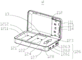
fig. 2 is a schematic view showing an open state of the multipurpose battery storage case of the present invention;
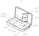
fig. 3 is a structural schematic view of a further opened state of the multipurpose battery storage case based on fig. 2;
fig. 4 is a reference view showing a usage state of the multipurpose battery storage case of the present invention;
description of reference numerals:
10. a multi-purpose battery storage case; 11. a box cover; 12. a box body; 13. a connecting member; 111. a card slot; 112. Rotating the clamping piece; 113. a snap ring; 114. buckling; 121. a first accommodating groove; 122. a second accommodating groove; 123. a functional region; 124; positive and negative electrodes; 126; an interface; 1261. Micro-USB; 1262. TYPE-C; 1263. USB; 127. a display lamp; 128. anti-skid lines; 1211. a trench wall; 1212. the bottom of the tank; 100. a battery; 200. an SD card.
[ detailed description ] embodiments
The following detailed description of the preferred embodiments of the present invention will be provided in conjunction with the accompanying drawings, so as to enable those skilled in the art to more easily understand the advantages and features of the present invention, and thereby define the scope of the invention more clearly and clearly. It is obvious that the described embodiments are only some of the embodiments of the present invention, and not all of them. Based on the embodiments of the present invention, all other embodiments obtained by a person of ordinary skill in the art without creative efforts belong to the protection scope of the present invention.
Referring to fig. 1, the present invention provides a multipurpose battery storage box 10, which is a cuboid, and includes a box cover 11 and a box body 12, wherein the box cover 11 is disposed on the box body 12, the box body 12 is used for storing batteries, specifically, batteries of photographic equipment, such as NP-FZ100 and LP-E6, and the box cover 11 is mainly used for covering and protecting the box body 12. The material of this multipurpose battery storage box 10 is any one of PP, PE, PC, PVC, ABS, PS.
Referring to fig. 2, the box body 12 is sequentially provided with a first receiving groove 121, a second receiving groove 122 and a functional area 123, wherein the first receiving groove 121 and the second receiving groove 122 are used for receiving batteries, and are independent from each other, the functional area 123 is used for charging and discharging the batteries, further, the first receiving groove 121 and the second receiving groove 122 both include a groove wall 1211 and a groove bottom 1212, the groove bottom 1212 is provided with a positive electrode 124 and a negative electrode 124, the positive electrode 124 and the negative electrode 124 are used for connecting the batteries so as to facilitate charging and discharging of the batteries, and the shapes and positions of the positive electrode 124 and the negative electrode 124 can be set according to the electrodes of the batteries. A functional circuit board (not shown) and an external interface 126 are disposed inside the functional region 123, and the interface 126 and the positive and negative electrodes 124 are connected to the circuit board through wires. The first receiving groove 121 and the second receiving groove 122 are both rectangular or columnar.
Further, the interface 126 includes an input interface and an output interface, specifically, the output interface is a USB1263, and the input interfaces are a TYPE-C1262 and a Micro-USB1261, respectively. The interface 126 is disposed at one side of the case 12, and when the battery is received in the multi-purpose battery receiving case 10, it not only plays a role of receiving the battery, but also can charge the battery through the input interface TYPE-C1262 and/or Micro-USB1261, and can charge various electronic products, such as mobile phones or tablets, through the output interface USB1263 by using the multi-purpose battery receiving case 10 storing the battery as a mobile power source.
The functional region 123 further includes a display lamp 127, and the display lamp 127 is used for displaying the state of the battery during charging and discharging and is disposed on the side of the case 12 adjacent to the interface 126. The number of the display lamps 127 is 4, and specifically, it is allocated that two display lamps 127 are provided for the first receiving groove 121, and two display lamps 127 are provided for the second receiving groove 122.
Referring to fig. 2, a connector 13 is further disposed between the box cover 11 and the box body 12 for connection, and when the box cover 11 is opened, the connector 13 connects the box cover 11 and the box body 12 without separation, thereby preventing the box cover 11 from being lost or damaged.
Referring to fig. 2 and 3, a card slot 111 for storing an SD card is disposed on a surface of the box cover 11 facing the functional area 123, the card slot 111 is a dual SD card slot 111, and the size of the single card slot 111 is set according to the size of the SD card on the market, which is not limited herein. Specifically, the box cover 11 is connected to the engaging groove 111 by a rotating engaging member 112, the rotating engaging members 112 are symmetrically disposed on two symmetrical sides of the box cover 11, and the engaging groove 111 is detachably connected to the rotating engaging member 112.
As a modified embodiment, the connection between the slot 111 and the rotation fastener 112 may also be a magnetic connection, a snap connection or an embedded fixed connection.
Referring to fig. 2 and fig. 3, a snap ring 113 is formed between the two SD slots 111 far from the rotational card 112, and the main shape of the snap ring is a square or circular ring with a hole formed in the middle, and a snap fastener 114 is disposed at the edge of the box cover 11 corresponding to the snap ring 113, and the snap fastener 114 is fastened by the snap ring 113 with a hole, so as to mainly prevent the auto-opening of the slot 111 and the loss of the stored SD card.
Further, the functional region 123 is provided with an anti-slip pattern 128 facing the upper surface of the card slot 111, and the anti-slip pattern 128 not only has an aesthetic effect, but also can achieve an anti-slip effect.
Referring to fig. 4, the multi-purpose battery storage box 10 stores the battery 100 and the SD card 200, so that the problem that the battery 100 and the SD card 200 are placed in disorder when the photographing device is used in normal times is solved, and further, the multi-purpose battery storage box 10 also solves the problem of single function, can charge the stored battery 100, and can be used as a mobile power source to charge electronic products through the external interface 126.
It is to be understood that the first receiving groove 121 and the second receiving groove 122 are collectively referred to as receiving grooves, and the distinction between the first and second is merely for convenience of description and is not intended to be limiting, and the multi-purpose battery storage case 10 includes no limiting number of receiving grooves.
The above description is only intended to illustrate the technical solution of the present invention, and not to limit it; although the present invention has been described in detail with reference to the foregoing embodiments, it should be understood by those skilled in the art that: the technical solutions described in the foregoing embodiments may still be modified, or some or all of the technical features may be equivalently replaced; all the equivalent structures or equivalent flow changes made by the contents of the specification and the drawings of the utility model, or the direct or indirect application in other related technical fields, are included in the patent protection scope of the utility model.