Energy-conserving building photovoltaic curtain that light energy utilization rate is high
Technical Field
The utility model belongs to the technical field of energy-conserving building, especially, relate to an energy-conserving building photovoltaic curtain that light energy utilization rate is high.
Background
The energy-saving building combines energy-saving technology and building technology, distinguishes building planning, and is a low-energy-consumption building designed after research is carried out on spatial distance and external space environment according to building orientation. The building photovoltaic curtain wall not only guarantees the building safety protection requirement, but also can generate electric energy for use. The solar energy is used as a green renewable energy source, has the characteristics of environmental protection and no pollution, accords with the production purpose of environmental protection, and is deeply loved by people.
However, the existing photovoltaic curtain wall fixes the photovoltaic panel on the surface of a building object, the angle is inconvenient to adjust, the angle cannot be changed along with the change of the angle of the solar ray, the sunlight cannot directly penetrate the photovoltaic curtain wall, and the solar energy utilization rate is low.
SUMMERY OF THE UTILITY MODEL
Not enough to prior art, the utility model aims to provide an energy-conserving building photovoltaic curtain that light energy utilization is high through setting up inclination adjustment mechanism and rotary mechanism, can adjust the angle of photovoltaic board, obtains the best angle of shining, has prolonged the illumination time simultaneously, has improved the utilization ratio of solar energy.
The utility model provides a following technical scheme:
an energy-saving building photovoltaic curtain wall with high light energy utilization rate comprises a frame and a photovoltaic panel; the frame is arranged on the surface of a building wall body; a plurality of photovoltaic panel supports are arranged on the inner side of the frame; the photovoltaic panel is arranged on the photovoltaic panel bracket; an inclination angle adjusting mechanism is arranged between the bottoms of the photovoltaic panel supports; the inclination angle adjusting mechanism is connected with a round rod; the round rod is connected with a threaded rod through a threaded cap, and the threaded rod is connected with a first motor; a rotating mechanism is arranged on the upper side of the angle adjusting mechanism; the rotating mechanism comprises a second motor and a worm; the output shaft of the second motor is connected with the worm; the worm is connected with the photovoltaic panel bracket.
Preferably, the inclination angle adjusting mechanism comprises a first guide rail, a second guide rail, a first ball, a second ball and a support rod; the first ball is arranged on the inner side of the first guide rail, and the second ball is arranged on the inner side of the second guide rail; the first guide rail is arranged at the upper end of the supporting rod, and the second guide rail is arranged at the lower end of the supporting rod.
Preferably, a first connecting rod and a second connecting rod are arranged between the first ball and the second ball.
Preferably, the support rod is provided with a worm wheel, and the worm wheel is meshed with the worm.
Preferably, the photovoltaic panel is disposed on a surface of the first connecting rod.
Preferably, the second ball is provided with a through hole, and the round rod is arranged in the through hole.
Preferably, the first motor is arranged on the support rod through a motor bracket.
Preferably, bearings are arranged at the upper end and the lower end of the supporting rod and are connected with the frame through bearing seats.
Preferably, the length of the first guide rail is smaller than the length of the second guide rail.
Compared with the prior art, the utility model discloses following beneficial effect has:
(1) the utility model relates to an energy-conserving building photovoltaic curtain that light energy utilization rate is high, through inclination adjustment mechanism, when rotatory threaded rod, the round bar drives the second ball and removes, realizes the purpose of photovoltaic board angle modulation in vertical plane.
(2) The utility model relates to an energy-conserving building photovoltaic curtain that light energy utilization rate is high through rotary mechanism, rotates the worm, and the bracing piece drives the rotatory certain angle of photovoltaic board, realizes that the photovoltaic board has prolonged the illumination time around space Z axle pivoted purpose.
(3) The utility model relates to an energy-conserving building photovoltaic curtain that light energy utilization rate is high through setting up the worm gear, has realized mechanism self-locking function, has improved the transmission efficiency of mechanism.
(4) The utility model relates to an energy-conserving building photovoltaic curtain that light energy utilization rate is high, the energy saving, simple to use, convenient operation.
Drawings
In order to more clearly illustrate the technical solutions of the embodiments of the present invention, the drawings that are required to be used in the embodiments will be briefly described below, it should be understood that the following drawings only illustrate some embodiments of the present invention, and therefore should not be considered as limiting the scope, and for those skilled in the art, other related drawings can be obtained according to the drawings without inventive efforts.
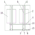
Fig. 1 is a main schematic diagram of the present invention.
Fig. 2 is a schematic side view of the present invention.
Fig. 3 is a schematic view of the first connecting rod and the second connecting rod of the present invention.
Fig. 4 is a schematic view of a second guide rail of the present invention.
In the figure: 1. a frame; 2. a support bar; 3. a worm gear; 4. a worm; 5. a second connecting rod; 6. a second guide rail; 7. a second ball bearing; 8. a round bar; 9. a first connecting rod; 10. a photovoltaic panel; 11. a first guide rail; 12. a first ball bearing; 13. a threaded cap; 14. a second motor.
Detailed Description
In order to make the objects, technical solutions and advantages of the embodiments of the present invention clearer, the drawings of the embodiments of the present invention will be combined to clearly and completely describe the technical solutions of the embodiments of the present invention. It is to be understood that the embodiments described are only some of the embodiments of the present invention, and not all of them. Based on the embodiments in the present invention, all other embodiments obtained by a person skilled in the art without creative work belong to the protection scope of the present invention.
Thus, the following detailed description of the embodiments of the present invention, presented in the accompanying drawings, is not intended to limit the scope of the invention, as claimed, but is merely representative of selected embodiments of the invention. Based on the embodiments in the present invention, all other embodiments obtained by a person skilled in the art without creative work belong to the protection scope of the present invention.
As shown in fig. 1-4, an energy-saving building photovoltaic curtain wall with high light energy utilization rate comprises a frame 1 and a photovoltaic panel 10; the frame 1 is arranged on the surface of a building wall; a plurality of photovoltaic panel supports are arranged on the inner side of the frame 1, and a plurality of photovoltaic panels are uniformly arranged in the frame; the photovoltaic panel 10 is arranged on a photovoltaic panel support; an inclination angle adjusting mechanism is arranged between the bottoms of the photovoltaic panel supports; the inclination angle adjusting mechanism is connected with a round rod 8; the round rod 8 is connected with a threaded rod through a threaded cap 13, the threaded rod is connected with a first motor, the first motor drives the threaded rod to rotate, and the round rod 8 moves under the action of the threaded cap 13, so that the aim of adjusting the inclination angle of the photovoltaic panel 10 in a vertical plane is fulfilled; a rotating mechanism is arranged on the upper side of the angle adjusting mechanism; the rotating mechanism comprises a second motor 14 and a worm 4; the output shaft of the second motor 14 is connected with the worm 4 through a coupler; the worm 4 is connected with the photovoltaic panel support, the rotating mechanism can enable the photovoltaic panel 10 to rotate for a certain angle, and the first motor and the second motor 14 are both servo motors and are electrically connected with an external power supply.
The inclination angle adjusting mechanism comprises a first guide rail 11, a second guide rail 6, a first ball 12, a second ball 7 and a support rod 2. The first guide rail 11 and the second guide rail 6 have the same structure; the first ball 12 is arranged inside the first guide rail 11, the second ball 7 is arranged inside the second guide rail 6, the first ball 12 can move in the first guide rail 11, and the second ball 7 can move in the second guide rail 6; the first guide rail 11 is arranged at the upper end of the support rod 2, and the second guide rail 6 is arranged at the lower end of the support rod 2. A first connecting rod 9 and a second connecting rod 5 are arranged between the first ball 12 and the second ball 7, the first connecting rod 9 is inserted in the second connecting rod 5, and the first connecting rod 9 can move in the second connecting rod 5; the first ball 12 and the second ball 7 are connected through a first connecting rod 9 and a second connecting rod 5.
The support rod 2 is provided with a worm wheel 3, the worm wheel 3 is meshed with a worm 4, the worm 4 is rotated, and the support rod 2 can rotate for a certain angle under the action of the worm wheel 3.
The photovoltaic panel 10 is arranged on the surface of the first connecting rod 9. The second ball 7 is provided with a through hole, the through hole passes through the center of the second ball 7, the round rod 8 is arranged in the through hole, and the round rod 8 penetrates through the second balls 7. The first motor is arranged on the support rod 2 through a motor bracket.
The upper end and the lower end of the support rod 2 are provided with bearings, the bearings are connected with the frame 1 through bearing seats, and the support rod 2 can rotate in the frame 1. The length of the first guide rail 11 is smaller than the length of the second guide rail 6.
The device obtained by the technical scheme is an energy-saving building photovoltaic curtain wall with high light energy utilization rate, in the working process of the device, the first motor is started according to actual needs, the first motor drives the threaded rod to rotate, the round rod 8 moves under the action of the threaded cap 13, and the second ball 7 is driven to further move, so that the aim of adjusting the inclination angle of the photovoltaic panel 10 in the vertical plane is fulfilled; the second motor 14 is started, the second motor 14 drives the worm 4 to rotate, the worm 4 acts on the worm wheel 3, the support rod 2 rotates for a certain angle under the action of the worm wheel 3, and the purpose that the photovoltaic panel 10 rotates around the space Z axis is achieved; in practical application, in the morning, the sun is located in the east, and the photovoltaic panel 10 is adjusted to rotate around the space Z axis to the sun side to receive the sunlight; at noon, the sun is positioned in the south-most direction, and the photovoltaic panel 10 is adjusted to rotate around the Z axis in the space towards the south; in the evening, the sun is positioned in the west, and the photovoltaic panel 10 is adjusted to rotate around the Z axis of the space to the west; by adjusting the angle of the photovoltaic panel 10, the time for the photovoltaic panel 10 to receive illumination is prolonged, and the light energy utilization rate is improved. The above is only to illustrate the working principle of the device, and the specific rotation angle is adjusted by combining the actual situation; through setting up inclination adjustment mechanism and rotary mechanism, can adjust the angle of photovoltaic board, obtain the best angle of illumination, prolong the illumination time simultaneously, improve the utilization ratio of light energy.
The above description is only a preferred embodiment of the present invention, and is not intended to limit the present invention, and various modifications and changes may be made by those skilled in the art; any modification, equivalent replacement, or improvement made within the spirit and principle of the present invention should be included in the protection scope of the present invention.