CN212703752U - Positioning module structure of bending machine - Google Patents
Positioning module structure of bending machine Download PDFInfo
- Publication number
- CN212703752U CN212703752U CN202020890572.2U CN202020890572U CN212703752U CN 212703752 U CN212703752 U CN 212703752U CN 202020890572 U CN202020890572 U CN 202020890572U CN 212703752 U CN212703752 U CN 212703752U
- Authority
- CN
- China
- Prior art keywords
- sides
- slide
- positioning
- lead screw
- module
- Prior art date
- Legal status (The legal status is an assumption and is not a legal conclusion. Google has not performed a legal analysis and makes no representation as to the accuracy of the status listed.)
- Active
Links
Images
Landscapes
- Bending Of Plates, Rods, And Pipes (AREA)
Abstract
A positioning module structure of a bending machine relates to a positioning module structure, which comprises module components, a motor and a positioning seat, wherein two module components are symmetrically arranged on the positioning seat in a left-right mode, any one module component comprises two guide plates, a slide way, a lead screw and a support seat, the two sides of the lower portion of the slide way are respectively provided with the support seats, the two guide plates are respectively fixed on the two sides between the two support seats, a gap is respectively arranged between the slide way and the two guide plates, the two ends of the lead screw are respectively fixed on the support seats on the two sides, a slide seat clamped outside the slide way is fixed on a lead screw nut of the lead screw, a fixing plate is respectively fixed on the slide seat, a long strip-shaped groove is arranged on the fixing plate, two rows of screw holes are symmetrically arranged on the two sides of the groove, a; the utility model discloses simple structure, the location axle sets up location more accurate in the breach, has improved the qualification rate of the process of bending greatly.
Description
Technical Field
The utility model relates to a location module structure especially relates to a location module structure of bender.
Background
As is known, a bending machine is a machining production device capable of bending the edge of a metal plate, and bends a workpiece by using bending cutter bodies at different angles at different stations; in the working process of the bending machine, a workpiece needs to be pressed and fixed on an operation table board, and then the subsequent bending process is carried out, because the sizes and the shapes of the plates are different, accurate positioning on the left side and the right side of the plates cannot be realized for the plates with notches on two sides, the bending or edge folding operation is not accurate, the waste of materials is caused, and a large amount of labor cost is also wasted; therefore, the positioning module of the bending machine is provided, which can accurately position two sides of plates with different sizes, and becomes a basic appeal for technical personnel in the field.
Disclosure of Invention
In order to overcome not enough among the background art, the utility model discloses a location module structure of bender.
In order to realize the purpose, the utility model adopts the following technical scheme:
a positioning module structure of a bending machine comprises module components, a motor and a positioning seat, wherein two module components are symmetrically arranged on the positioning seat left and right, the outer ends of the two module components are respectively connected with the motor, any one module component comprises two guide plates, a slide way, a screw rod and a supporting seat, both sides of the lower part of the slideway are provided with supporting seats, two guide plates are respectively fixed on both sides between the supporting seats on both sides, a gap is arranged between the slideway and the two guide plates, both ends of the screw rod are respectively fixed on the supporting seats on both sides, a slide seat clamped outside the slide way is fixed on a lead screw nut of the lead screw, fixing plates are fixed on the slide seats, a strip-shaped groove is arranged on the fixing plate, two rows of screw holes are symmetrically formed in two sides of the groove, positioning blocks are arranged in the groove, vertically-arranged positioning shafts are arranged on the upper portions of the positioning blocks, and the positioning blocks are fixed in the grooves of the fixing plates through screws.
The positioning module structure of the bending machine is characterized in that the outer end of the lead screw is connected with a motor.
Since the technical scheme is used, the utility model discloses following beneficial effect has:
the positioning module structure of the utility model drives the lead screw through the driving motor to make the fixed plate 2 move on the slideway 8, the upper part of the fixed plate 2 is provided with the positioning block 3 which is finely adjusted by screws, and the upper part of the positioning block 3 is fixed with the positioning shaft 11 which can position the plate with a gap; the utility model discloses simple structure, convenient to use, location axle 11 sets up and fixes a position more accurately in the breach, has improved the qualification rate of the process of bending greatly.
Drawings
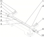
Fig. 1 is a schematic structural diagram of the present invention;
in the figure: 1. a module assembly; 2. a fixing plate; 3. positioning blocks; 4. a motor; 5. a supporting seat; 6. positioning seats; 7. a screw hole; 8. a slideway; 9. a slide base; 10. a guide plate; 11. and (5) positioning the shaft.
Detailed Description
The invention will be explained in more detail by the following examples, which disclose the invention and are intended to protect all technical improvements within the scope of the invention.
The positioning module structure of the bending machine, which is described by combining the attached figure 1, comprises module assemblies 1, a motor 4 and a positioning seat 6, wherein two module assemblies 1 are symmetrically arranged on the positioning seat 6 left and right, the outer ends of the two module assemblies 1 are connected with the motor 4, any one module assembly 1 comprises two guide plates 10, a slide way 8, a screw rod and a support seat 5, the support seats 5 are arranged on two sides of the lower part of the slide way 8, the two guide plates 10 are respectively fixed on two sides between the two support seats 5 on two sides, a gap is arranged between the slide way 8 and the two guide plates, two ends of the screw rod are respectively fixed on the support seats 5 on two sides, a slide seat 9 clamped outside the slide way 8 is fixed on a screw nut of the screw rod, a fixing plate 2 is fixed on the slide seat 9, a strip-shaped groove is arranged on the fixing plate 2, the upper part of the positioning block 3 is provided with a positioning shaft 11 which is vertically arranged, and the positioning block 3 is fixed in a groove of the fixing plate 2 through a screw.
The positioning module structure of the bending machine is characterized in that the outer end of the lead screw is connected with a motor 4.
Implement location module structure of bender, when using, adjust the distance between two fixed plates 2 according to the size of sheet material, two motors 4 drive the lead screw in the module 1 respectively, control two lead screws and drive fixed plate 2 on two slides 9 respectively and remove on the upper portion of slide 8, locating piece 3 is adjusted on the length direction of fixed plate 2 through the screw, make the location axle 11 card on 3 upper portions of locating piece in the breach on the face of sheet material both sides, thereby it is more reliable to the sheet material location that has the breach.
The part of the utility model not detailed is prior art.
The embodiments selected for the purpose of disclosing the invention, are presently considered to be suitable, it being understood, however, that the invention is intended to cover all variations and modifications of the embodiments, which fall within the scope of the concept and the utility model.
Claims (2)
1. The utility model provides a location module structure of bender, includes module subassembly, motor and positioning seat, characterized by: bilateral symmetry is equipped with two module subassemblies on the positioning seat, the outer end of two module subassemblies all is connected with the motor, arbitrary one module subassembly all includes two baffles, the slide, lead screw and supporting seat, both sides all are equipped with the supporting seat in the lower part of slide, two baffles are fixed respectively on both sides between the supporting seat of both sides, all be equipped with the clearance between slide and two baffles, the both ends of lead screw are fixed respectively on the supporting seat of both sides, be fixed with the slide of joint in the slide outside on the screw nut of lead screw, all be fixed with the fixed plate on the slide, the higher authority of fixed plate is equipped with rectangular shape recess, both sides symmetry at the recess is equipped with two rows of screws, all be equipped with the locating piece in the recess, be equipped with the location axle of vertical setting on the upper.
2. The positioning module structure of bending machine according to claim 1, wherein: the outer ends of the lead screws are connected with motors.
Priority Applications (1)
| Application Number | Priority Date | Filing Date | Title |
|---|---|---|---|
| CN202020890572.2U CN212703752U (en) | 2020-05-25 | 2020-05-25 | Positioning module structure of bending machine |
Applications Claiming Priority (1)
| Application Number | Priority Date | Filing Date | Title |
|---|---|---|---|
| CN202020890572.2U CN212703752U (en) | 2020-05-25 | 2020-05-25 | Positioning module structure of bending machine |
Publications (1)
| Publication Number | Publication Date |
|---|---|
| CN212703752U true CN212703752U (en) | 2021-03-16 |
Family
ID=74946890
Family Applications (1)
| Application Number | Title | Priority Date | Filing Date |
|---|---|---|---|
| CN202020890572.2U Active CN212703752U (en) | 2020-05-25 | 2020-05-25 | Positioning module structure of bending machine |
Country Status (1)
| Country | Link |
|---|---|
| CN (1) | CN212703752U (en) |
-
2020
- 2020-05-25 CN CN202020890572.2U patent/CN212703752U/en active Active
Similar Documents
| Publication | Publication Date | Title |
|---|---|---|
| US4682401A (en) | Multiple processing machine | |
| CN213729679U (en) | Two-chuck movable pipe cutting machine | |
| CN104625745A (en) | A gantry type composite automatic sheet metal processing center | |
| CN106945088B (en) | A kind of styrofoam trimming mechanism | |
| CN201816387U (en) | Dual-purpose engraver | |
| CN215467434U (en) | Copper bar automatic positioning puncher | |
| CN101251961B (en) | Modularization four axis miniature teaching numerical control machine | |
| CN213001969U (en) | Multi-edge transverse unequal-distance high-precision bending device for ultra-long tower tube | |
| CN212884418U (en) | A copper row punching positioning device | |
| CN205381074U (en) | Small -size horizontal cnc engraving and milling machine | |
| CN210755924U (en) | Supporting device for laser processing piece | |
| CN219093228U (en) | Equidirectional double-sided bending machine | |
| CN217551330U (en) | Metal cutting machine tool with adjustable cutting surface | |
| CN215467627U (en) | Stamping positioning device | |
| CN210099048U (en) | Numerical control machine tool for machining coil cushion block | |
| CN214135068U (en) | Gantry machining center | |
| CN209175256U (en) | A kind of digital stamping and laser cutting compounding machine | |
| CN210232229U (en) | Equipment for milling four side surfaces of rectangular plate by one-step clamping | |
| CN210414839U (en) | Novel positioning fixture mechanism of drilling equipment | |
| CN202571371U (en) | Multi-hole boring mill with combined boring rod | |
| CN211682585U (en) | Woodworking stop point positioning and milling equipment | |
| CN221773279U (en) | A punching device for power distribution cabinet production | |
| CN223070503U (en) | Milling device | |
| CN223288859U (en) | A tower punching machine with clamping and conveying function | |
| CN212419280U (en) | Frame frock of punching a hole |
Legal Events
| Date | Code | Title | Description |
|---|---|---|---|
| GR01 | Patent grant | ||
| GR01 | Patent grant |