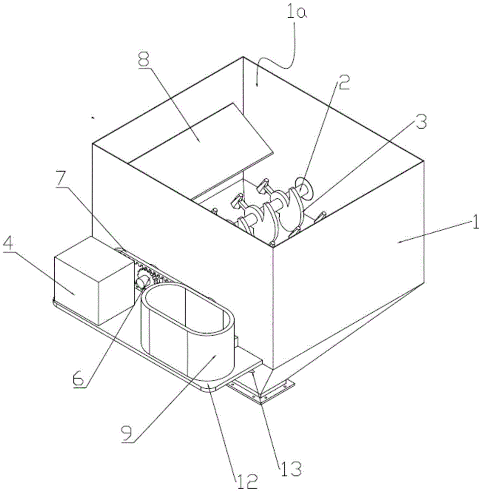
Charging hopper with crushing structure
Technical Field
The utility model relates to a loading hopper technical field especially relates to a loading hopper with broken structure.
Background
In the process of processing production, often need smash and carry the raw materials, adopt crushing structure to carry out shredding to the raw materials when smashing, can influence the machining efficiency and the processingquality of subsequent processing procedure to the crushing degree of raw materials.
The existing charging hopper is generally used for continuously feeding, does not have a crushing function, and part of the charging hopper with the crushing function is not uniform in size of raw materials, and the crushing structure is unreasonable in design, so that the crushing structure cannot crush the raw materials sufficiently, and the phenomenon that the raw materials block a discharge port can occur.
SUMMERY OF THE UTILITY MODEL
The technical proposal adopted by the utility model is that the charging hopper with a crushing structure is provided, which comprises a hopper body, the upper end of the hopper body is provided with a feed inlet, the lower end of the hopper body is provided with a discharge outlet, a rotating shaft which penetrates through the side wall of the hopper body is rotationally arranged in the hopper body, a plurality of crushing blades for crushing the raw materials in the hopper body are arranged on the rotating shaft at intervals, the crushing blade comprises a blade body, one end of the blade body is provided with an arc-shaped blade with an upward pointed end, the other end of the blade body is provided with a crushing cone, the arc-shaped blade and the crushing cone are respectively positioned at two sides of the rotating shaft, a driving motor is fixedly arranged outside the hopper body, a driving gear is arranged on an output shaft of the driving motor, driven gear is installed to the one end of pivot, the driving gear passes through rubber gear belt drive with driven gear and is connected.
Furthermore, the hopper body is internally provided with guide plates which are positioned on two sides of the rotating shaft relatively, one ends of the guide plates are fixed on the inner wall of the hopper body, and the other ends of the guide plates are obliquely arranged towards the crushing cone.
Further, the hopper body is provided with the compounding groove that is used for adding liquid material or powdered material outward, the lower extreme in compounding groove is equipped with the conveyer pipe with this internal intercommunication of hopper, the conveyer pipe is located the below of pivot.
Furthermore, the rotating shafts are arranged in the hopper body at intervals, the driven gears are arranged at two intervals, and the two crushing blades on the rotating shafts which are adjacently arranged are correspondingly arranged.
Further, a bearing is arranged on the side wall of the hopper body, and one end, far away from the driven gear, of the rotating shaft is installed on the hopper body through the bearing.
Further, a base plate is horizontally arranged on the outer wall of the hopper body, a plurality of supporting plates are arranged between the hopper body and the base plate, and the driving motor, the mixing groove and the conveying pipe are arranged on the base plate.
Compared with the prior art the utility model discloses technical scheme's beneficial effect does:
1. the utility model provides a pair of loading hopper with broken structure sets up arc blade and the broken awl that has the tip in this internal pivot of hopper, and the raw materials is broken up or is bored brokenly through broken awl earlier, then smashes through arc blade again, makes to mix garrulously more abundant, mixes garrulous effect better, and can not block up the discharge gate, is convenient for last material loading.
2. Set up the deflector in the both sides of pivot, guide the raw materials to broken awl or arc blade's tip on, tentatively refine the raw materials earlier, the arc blade of being convenient for further smashes the raw materials, avoids the raw materials card between broken awl head and arc blade's pointed end.
3. Through setting up the compounding groove, be convenient for mix the material that adds with this internal kibbling raw materials of hopper.
Drawings
In order to more clearly illustrate the technical solutions in the embodiments of the present invention, the drawings needed to be used in the description of the embodiments will be briefly described below, and it is obvious that the drawings in the following description are only some embodiments of the present invention, and it is obvious for those skilled in the art to obtain other drawings without creative efforts.
Fig. 1 is a perspective view of a hopper with a crushing structure provided by the present invention;
FIG. 2 is a perspective view of another aspect of a hopper with a crushing structure;
fig. 3 is a top view of a hopper with a crushing structure provided by the present invention;
fig. 4 is a schematic structural diagram of the rotating shaft and the crushing blade provided by the present invention.
Wherein the reference numerals are:
1. hopper body, 1a, feed inlet, 1b, discharge gate, 2, pivot, 3, crushing blade, 31, blade body, 32, arc blade, 33, broken awl, 4, driving motor, 5, driving gear, 6, driven gear, 7, rubber gear area, 8, deflector, 9, compounding groove, 10, conveyer pipe, 11, bearing, 12, base plate, 13, backup pad.
Detailed Description
The invention will be further explained with reference to the drawings and the specific embodiments.
Example 1
Please refer to fig. 1-4, the utility model provides a pair of loading hopper with crushing structure, including hopper body 1, hopper body 1's upper end is equipped with feed inlet 1a, hopper body 1's lower extreme is equipped with discharge gate 1b, hopper body 1 internal rotation is equipped with the pivot 2 that runs through hopper body 1 lateral wall setting, the interval is equipped with a plurality of crushing blades 3 that are used for carrying out kibbling to the raw materials in hopper body 1 in pivot 2, crushing blade 3 includes blade body 31, blade body 31's one end is equipped with has sharp-end arc blade 32 up, blade body 31's the other end is equipped with broken awl 33, arc blade 32 and broken awl 33 are located the both sides of pivot 2 respectively, hopper body 1 external fixation is equipped with driving motor 4, be equipped with driving gear 5 on driving motor 4's the output shaft, driven gear 6 is installed to the one end of pivot 2, driving gear 5 passes through rubber gear belt 7 transmission with driven gear 6 and is. Wherein, the driving gear 5 and the driven gear 6 are respectively meshed with the rubber gear belt 7.
Set up arc blade 32 and broken awl 33 that have the tip on pivot 2 in hopper body 1, the raw materials is broken up or is bored brokenly through broken awl 33 earlier, then smashes through arc blade 32 again, makes and smashes more abundant, and crushing effect is better, and can not block up discharge gate 1b, is convenient for last material loading.
Specifically, a bearing 11 is arranged on the side wall of the hopper body 1, and one end of the rotating shaft 2, which is far away from the driven gear 6, is mounted on the hopper body 1 through the bearing 11.
Specifically, pivot 2 keeps the interval relatively in hopper body 1 to be equipped with two, and driven gear 6 is equipped with two, and two adjacent epaxial crushing blade 3 of two pivots 2 that set up correspond the setting to improve the crushing effect and the efficiency of loading hopper.
Specifically, in order to ensure the relative uniformity of the crushed particles of the raw material, the rotating shaft 2 and the crushing blades 3 are provided with a plurality of groups from top to bottom.
Preferably, the hopper body 1 is internally and oppositely provided with guide plates 8 at two sides of the rotating shaft 2, one end of each guide plate 8 is fixed on the inner wall of the hopper body 1, and the other end of each guide plate 8 is obliquely arranged towards the crushing cone 33 or the tip of the arc-shaped blade 32.
Set up deflector 8 in the both sides of pivot 2, guide the raw materials to broken awl 33 or arc blade 32 on the tip, tentatively refine the raw materials earlier, the arc blade 32 of being convenient for is further smashed the raw materials, avoids the raw materials card between broken awl 33 and arc blade 32's pointed end.
Preferably, a mixing groove 9 for adding liquid materials or powder materials is arranged outside the hopper body 1, a conveying pipe 10 communicated with the inside of the hopper body 1 is arranged at the lower end of the mixing groove 9, and the conveying pipe 10 is positioned below the rotating shaft 2.
Through setting up mixing tank 9, be convenient for mix the material that adds with kibbling raw materials in the hopper body 1, follow-up stirring processing again can prevent that certain raw materials from not being taken to the loading hopper lower extreme by the liquid material that adds after fully smashing.
Specifically, a lid (not shown) is provided at the upper end of the mixing tank 9.
Preferably, a base plate 12 is horizontally arranged on the outer wall of the hopper body 1, a plurality of support plates 13 are arranged between the hopper body 1 and the base plate 12, and the driving motor 4, the mixing trough 9 and the conveying pipe 10 are arranged on the base plate 12.
Specifically, hopper body 1 is including the vertical feeding section and the slope feeding section that are connected, and feed inlet 1a sets up in the upper end of vertical feeding section, and discharge gate 1b sets up at the lower extreme of slope feeding section, and on the outer wall of the fixed and vertical feeding section of base plate 12, the lower extreme of backup pad 13 is fixed with the outer wall of slope feeding section, the lower fixed surface of upper end and base plate 12.
The utility model provides a loading hopper with broken structure is applicable to the breakage and the material loading of the great raw materials of particle diameter, for example raw materials such as watermelon, apple, pumpkin, coal ball.
The foregoing has described in detail preferred embodiments of the present invention. It should be understood that numerous modifications and variations can be devised by those skilled in the art in light of the teachings of the present invention without undue experimentation. Therefore, the technical solutions that can be obtained by a person skilled in the art through logic analysis, reasoning or limited experiments based on the prior art according to the concepts of the present invention should be within the scope of protection defined by the claims.