CN212676137U - Interlocking device for grounding switch cabinet door - Google Patents
Interlocking device for grounding switch cabinet door Download PDFInfo
- Publication number
- CN212676137U CN212676137U CN202021514723.0U CN202021514723U CN212676137U CN 212676137 U CN212676137 U CN 212676137U CN 202021514723 U CN202021514723 U CN 202021514723U CN 212676137 U CN212676137 U CN 212676137U
- Authority
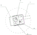
- CN
- China
- Prior art keywords
- interlocking
- cabinet door
- operating shaft
- operating
- grounding switch
- Prior art date
- Legal status (The legal status is an assumption and is not a legal conclusion. Google has not performed a legal analysis and makes no representation as to the accuracy of the status listed.)
- Active
Links
Images
Landscapes
- Patch Boards (AREA)
Abstract
An interlocking device for a grounding switch cabinet door. The problem of the back cabinet door interlocking of current cubical switchboard unreliable, and operating axis rotate the difficulty is solved. The first operating shaft is connected with the second operating shaft through a connecting crank arm, an operating part is arranged at one end of the first operating shaft, a first bevel gear is arranged at the other end of the first operating shaft and is meshed with a second bevel gear arranged on a switch cabinet body, the second bevel gear is connected with a grounding switch through a grounding crank arm and is used for operating the grounding switch to close and open a switch, and an interlocking mechanism used for interlocking with a rear cabinet door is arranged on the second operating shaft. The beneficial effects of the utility model are that, through the bevel gear transmission for the operating shaft rotates more laborsavingly, simple structure, and the transmission is reliable, and convenient operation has set up interlocking device moreover and has avoided the back cabinet door maloperation to open, and the security is higher.
Description
Technical Field
The utility model relates to a cubical switchboard, concretely relates to earthing switch cabinet door interlock.
Background
Along with the progress of the manufacturing process of the power equipment, the power supply device of the power equipment is more and more stable, and in order to further improve the automation degree of the power industry, all units in the power supply industry comprehensively develop unattended transformation of a transformer substation.
The switch cabinet is an electrical device, the external line of the switch cabinet firstly enters a main control switch in the cabinet and then enters a branch control switch, and each branch is arranged according to the requirement. Such as meters, automatic controls, magnetic switches of motors, various alternating current contactors, and the like, some of which are also provided with high-voltage chambers and low-voltage chamber switch cabinets, and high-voltage buses, such as power plants, and some of which are also provided with low-frequency load shedding for keeping main equipment. The grounding switch is a mechanical switch used for a circuit grounding part, the grounding switch in the high-voltage switch cabinet is used for ensuring personal safety during maintenance, and the mechanical grounding device is used for grounding and is used for replacing a portable ground wire, so that equipment is grounded during maintenance of high-voltage equipment and circuits, and personal safety is protected; the artificial grounding is caused, and the protection requirement is met. The earthing switch is arranged beside the disconnecting switches on the two sides of the circuit breaker, and the earthing switch plays a role in earthing the two sides when the circuit breaker is overhauled. The existing grounding switch is usually driven to be disconnected or closed by a grounding operation main shaft, an interlocking device is arranged on the grounding operation main shaft, and when a rear door (sealing plate) is closed, the interlocking device is unlocked to operate the grounding switch; when the grounding switch is in a closing state and the back door (closing plate) is opened, the interlocking device is locked, so that the grounding operation main shaft cannot rotate, the grounding switch cannot be opened, and the safety of maintainers is ensured. But current interlocking structure is unreliable, and back door interlocking and operating axis be the linear type setting, and the operation is hard, and product insulation distance is shorter, has certain potential safety hazard.
SUMMERY OF THE UTILITY MODEL
For the back cabinet door interlocking unreliable of solving among the background art current cubical switchboard, and the operating axis rotates the problem of difficulty, the utility model provides a grounding switch cabinet door interlock.
The technical scheme of the utility model is that: the utility model provides a ground switch cabinet door interlock, includes first operating axis and second operating axis, first operating axis be connected through connecting the turning arm with the second operating axis, the one end of first operating axis is equipped with the operation portion, is equipped with first bevel gear on the other end, first bevel gear with locate the second bevel gear on the cubical switchboard cabinet body and mesh mutually, the second bevel gear be connected with earthing switch through ground connecting the turning arm and be used for operating earthing switch closing and separating brake, the second operating axis on be equipped with and be used for interlocking with back cabinet door looks interlocking device.
As an improvement of the utility model, the first operating axis and the second operating axis are arranged in a staggered manner from top to bottom.
As a further improvement of the utility model, the connecting crank arm is C-shaped.
As a further improvement of the utility model, the first bevel gears have two, and two first bevel gears are symmetrically arranged on the second bevel gear.
As a further improvement of the present invention, the number of teeth of the first bevel gear is less than the number of teeth of the second bevel gear.
As the utility model discloses a further improvement, interlocking device including being fixed in the switch cabinet support on the body, the support on be equipped with the interlocking pin, the second operating axis on be equipped with the interlocking plate, the interlocking pin have and make interlocking plate and second operating axis rotate spacing primary importance and back cabinet door when the earthing switch combined floodgate back cabinet door is opened and make interlocking plate free rotation's second position when the unblock is closed to the back cabinet door, the interlocking plate avoid back cabinet door maloperation to open through rotating interlocking back cabinet door when the interlocking pin is in the second position.
As a further improvement of the present invention, the interlocking pin is provided with a reset member, and the reset member has a movement tendency that the driving interlocking pin tends to the first position.
As a further improvement of the present invention, the operation portion is disposed in the mounting frame, the mounting frame is provided with an operation interlocking frame, the operation interlocking frame has a first position for shielding the operation portion and a second position for opening the operation portion driven by the driving member.
As a further improvement of the utility model, the operating part overcoat be equipped with indicate the lid and with indicate the lid linkage to be connected, the instruction lid locate the mounting bracket in.
As a further improvement of the utility model, the first operating shaft on be equipped with the sector plate, the mounting bracket on be equipped with and be used for the rotatory spacing stopper of sector plate.
The beneficial effects of the utility model are that, through the bevel gear transmission for the operating shaft rotates more laborsavingly, simple structure, and the transmission is reliable, and convenient operation has set up interlocking device moreover and has avoided the back cabinet door maloperation to open, and the security is higher. The utility model discloses simple structure still has, convenient assembling, and the action is reliable, advantages such as long service life.
Drawings
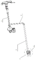
Fig. 1 is a schematic structural diagram of an embodiment of the present invention.
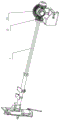
Fig. 2 is a schematic structural view of fig. 1 at a first operation axis 1.
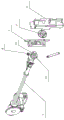
Fig. 3 is a schematic diagram of the exploded structure of fig. 2.
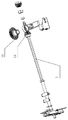
Fig. 4 is a schematic structural view in the other direction of fig. 2.
Fig. 5 is an enlarged schematic view of the structure at I in fig. 1.
In the figure, 1, a first operating shaft; 11. an operation section; 12. a first bevel gear; 13. a second bevel gear; 14. a sector plate; 2. a second operating shaft; 3. connecting a crank arm; 4. an interlock mechanism; 41. a support; 42. an interlock pin; 43. an interlock plate; 44. a reset member; 5. a mounting frame; 6. operating an interlocking frame; 7. an indicating cover; 8. and a limiting block.
Detailed Description
The embodiments of the present invention will be further explained with reference to the accompanying drawings:
as shown in fig. 1 and fig. 2-5, an interlocking device for a grounding switch cabinet door comprises a first operating shaft 1 and a second operating shaft 2, wherein the first operating shaft 1 is connected with the second operating shaft 2 through a connecting crank arm 3, one end of the first operating shaft 1 is provided with an operating part 11, the other end of the first operating shaft is provided with a first bevel gear 12, the first bevel gear 12 is engaged with a second bevel gear 13 arranged on a switch cabinet body, the second bevel gear 13 is connected with a grounding switch through the grounding crank arm and is used for operating the grounding switch to close or open a brake, and the second operating shaft 2 is provided with an interlocking mechanism 4 used for interlocking with a rear cabinet door. The beneficial effects of the utility model are that, through the bevel gear transmission for the operating shaft rotates more laborsavingly, simple structure, and the transmission is reliable, and convenient operation has set up interlocking device moreover and has avoided the back cabinet door maloperation to open, and the security is higher. The utility model discloses simple structure still has, convenient assembling, and the action is reliable, advantages such as long service life.
The first operating shaft 1 and the second operating shaft 2 are arranged in a vertically staggered mode. First operating axis and second operating axis dislocation set make to avoid mechanism and ground connection female arranging too closely, provide sufficient air insulation distance, avoid setting up insulating cover, and the product security is higher.
The connecting crank arm 3 is C-shaped. Such a configuration makes the first and second operation shafts operate reliably.
The number of the first bevel gears 12 is two, and the two first bevel gears 12 are symmetrically arranged on the second bevel gear 13. Specifically, the number of teeth of the first bevel gear 12 is smaller than that of the second bevel gear 13. More specifically, the number of teeth of the first bevel gear is half that of the second bevel gear, so that the first operating shaft can be operated more easily, and different gear ratios can be set according to needs.
Interlocking device 4 including being fixed in the support 41 on the switch cabinet body, support 41 on be equipped with interlocking pin 42, second operating shaft 2 on be equipped with interlocking plate 43, interlocking pin 42 have make interlocking plate 43 and second operating shaft 2 rotate spacing first position and make interlocking plate 43 freely rotate when the back cabinet door closes the unblock when earthing switch closes the back cabinet door and opens, interlocking plate 43 avoid the back cabinet door maloperation to open through rotating the interlocking back cabinet door when interlocking pin 42 is in the second position. Such structure makes the cabinet door interlocking of back reliably avoid the maloperation to open the cabinet door.
The interlocking pin 42 is provided with a resetting piece 44, and the resetting piece 44 has a movement trend for driving the interlocking pin 42 to the first position. The setting of piece that resets makes the interlocking pin can carry out the reversal interlocking to the second operating axis spacing when the cabinet door is opened, avoids second operating axis maloperation.
The operation portion 11 locate in the mounting bracket 5, the mounting bracket 5 on be equipped with operation interlocking frame 6, operation interlocking frame 6 have the first position of sheltering from operation portion 11 and open the driving piece drive operation portion 11 pivoted second position of being convenient for. Therefore, the operation part of the first operation shaft can be exposed only by pressing the operation interlocking frame, and the safety is higher.
The operating part 11 overcoat be equipped with instruct lid 7 and with instruct lid 7 linkage connection, instruct lid 7 locate the mounting bracket 5 in. Therefore, the state of the product can be indicated, and misoperation of workers is avoided.
The first operating shaft 1 is provided with a sector plate 14, and the mounting frame 5 is provided with a limiting block 8 for limiting the rotation of the sector plate 14. The sector plate plays a role in closing limiting, and after the sector plate rotates by 180 degrees, the sector plate interferes with a limiting block to complete in-place limiting.
In the description of the present invention, it should be noted that the terms "center", "longitudinal", "lateral", "up", "down", "front", "back", "left", "right", "vertical", "horizontal", "top", "bottom", "inner", "outer", and the like indicate the orientation or positional relationship based on the orientation or positional relationship shown in the drawings, and are only for convenience of description and simplification of the description, but do not indicate or imply that the device or element referred to must have a specific orientation, be constructed and operated in a specific orientation, and thus, should not be construed as limiting the present invention. Furthermore, the terms "first" and "second" are used for descriptive purposes only and are not to be construed as indicating or implying relative importance.
In the description of the present invention, it is to be noted that, unless otherwise explicitly specified or limited, the terms "mounted," "connected," and "connected" are to be construed broadly, and may be, for example, fixedly connected, detachably connected, or integrally connected; can be mechanically or electrically connected; they may be connected directly or indirectly through intervening media, or they may be interconnected between two elements. The specific meaning of the above terms in the present invention can be understood in specific cases to those skilled in the art. In addition, in the description of the present invention, "a plurality" means two or more unless otherwise specified.
The skilled person should understand that: although the present invention has been described in accordance with the above embodiments, the inventive concept is not limited to this embodiment, and any modification of the inventive concept will be included in the scope of the patent claims.
Claims (10)
1. The interlocking device for the cabinet door of the grounding switch comprises a first operating shaft (1) and a second operating shaft (2), and is characterized in that the first operating shaft (1) is connected with the second operating shaft (2) through a connecting crank arm (3), one end of the first operating shaft (1) is provided with an operating part (11), the other end of the first operating shaft is provided with a first bevel gear (12), the first bevel gear (12) is meshed with a second bevel gear (13) arranged on a cabinet body of the switch cabinet, the second bevel gear (13) is connected with the grounding switch through the grounding crank arm and is used for operating the closing and opening of the grounding switch, and an interlocking mechanism (4) used for interlocking with a rear cabinet door is arranged on the second operating shaft (2).
2. The interlocking device of the grounding switch cabinet door according to claim 1, wherein the first operating shaft (1) and the second operating shaft (2) are arranged in a vertically staggered manner.
3. The interlocking device for grounding switch cabinet doors according to claim 1, characterized in that said connecting crank arm (3) is C-shaped.
4. The interlocking device for the door of the grounding switch cabinet according to claim 1, wherein the number of the first bevel gears (12) is two, and the two first bevel gears (12) are symmetrically arranged on the second bevel gear (13).
5. A grounding switch cabinet door interlock according to claim 1, characterized in that the number of teeth of said first bevel gear (12) is less than the number of teeth of said second bevel gear (13).
6. The interlocking device for the grounding switch cabinet door according to claim 1, wherein the interlocking mechanism (4) comprises a support (41) fixed on the cabinet body of the switch cabinet, an interlocking pin (42) is arranged on the support (41), an interlocking plate (43) is arranged on the second operating shaft (2), the interlocking pin (42) has a first position enabling the interlocking plate (43) and the second operating shaft (2) to rotate for limiting when the cabinet door is opened after the grounding switch is closed and a second position enabling the interlocking plate (43) to rotate freely when the cabinet door is closed and unlocked, and the interlocking plate (43) prevents the cabinet door from being opened by misoperation when the interlocking pin (42) is in the second position by rotating the interlocking cabinet door.
7. An earthing switch cabinet door interlock according to claim 6, characterized in that said interlock pin (42) is provided with a reset member (44), said reset member (44) having a tendency to drive the interlock pin (42) towards the first position.
8. An interlocking device for a grounding switch cabinet door according to claim 1, characterized in that the operating part (11) is arranged in a mounting frame (5), an operating interlocking frame (6) is arranged on the mounting frame (5), and the operating interlocking frame (6) has a first position for shielding the operating part (11) and a second position for opening to facilitate the driving part to drive the operating part (11) to rotate.
9. The interlocking device for the door of the grounding switch cabinet according to claim 8, characterized in that the operating part (11) is sleeved with an indicating cover (7) and is in linkage connection with the indicating cover (7), and the indicating cover (7) is arranged in the mounting frame (5).
10. The interlocking device of the grounding switch cabinet door according to claim 8, wherein the first operating shaft (1) is provided with a sector plate (14), and the mounting frame (5) is provided with a limiting block (8) for limiting the rotation of the sector plate (14).
Priority Applications (1)
| Application Number | Priority Date | Filing Date | Title |
|---|---|---|---|
| CN202021514723.0U CN212676137U (en) | 2020-07-28 | 2020-07-28 | Interlocking device for grounding switch cabinet door |
Applications Claiming Priority (1)
| Application Number | Priority Date | Filing Date | Title |
|---|---|---|---|
| CN202021514723.0U CN212676137U (en) | 2020-07-28 | 2020-07-28 | Interlocking device for grounding switch cabinet door |
Publications (1)
| Publication Number | Publication Date |
|---|---|
| CN212676137U true CN212676137U (en) | 2021-03-09 |
Family
ID=74815902
Family Applications (1)
| Application Number | Title | Priority Date | Filing Date |
|---|---|---|---|
| CN202021514723.0U Active CN212676137U (en) | 2020-07-28 | 2020-07-28 | Interlocking device for grounding switch cabinet door |
Country Status (1)
| Country | Link |
|---|---|
| CN (1) | CN212676137U (en) |
Cited By (2)
| Publication number | Priority date | Publication date | Assignee | Title |
|---|---|---|---|---|
| CN114141558A (en) * | 2021-11-29 | 2022-03-04 | 云南昆宝电气科技有限公司 | Intelligent interlocking device for high-voltage cabinet capable of being safely operated |
| CN115764556A (en) * | 2022-08-19 | 2023-03-07 | 四川汉舟电气股份有限公司 | The installation structure and installation method of the floor knife used above the electric control cabinet |
-
2020
- 2020-07-28 CN CN202021514723.0U patent/CN212676137U/en active Active
Cited By (2)
| Publication number | Priority date | Publication date | Assignee | Title |
|---|---|---|---|---|
| CN114141558A (en) * | 2021-11-29 | 2022-03-04 | 云南昆宝电气科技有限公司 | Intelligent interlocking device for high-voltage cabinet capable of being safely operated |
| CN115764556A (en) * | 2022-08-19 | 2023-03-07 | 四川汉舟电气股份有限公司 | The installation structure and installation method of the floor knife used above the electric control cabinet |
Similar Documents
| Publication | Publication Date | Title |
|---|---|---|
| JP4848018B2 (en) | Closed switchboard for electric power | |
| CN101150247A (en) | Vacuum Insulated Switchgear | |
| CN103441439A (en) | Switch cabinet equipped with isolating switches, vacuum circuit breakers and grounding switches | |
| CN108305813A (en) | A kind of output is walked around the single motor three position mechanism at angle more | |
| CN203218164U (en) | Interlock, indication and auxiliary switch structure of single-motor three-station mechanism | |
| CN203434502U (en) | A switch cabinet provided with isolating switches, vacuum circuit breakers, and grounding switches | |
| CN217656221U (en) | Switch cabinet | |
| CN105470830A (en) | Small-sized fixed type switch cabinet for realizing five-prevention by single-hole single-shaft operation and control method for small-sized fixed type switch cabinet | |
| CN206301707U (en) | A high-voltage switchgear with isolating switch and interlocking parts | |
| CN219226893U (en) | Intelligent switch cabinet with five-prevention interlocking function | |
| CN201392989Y (en) | Top entry and exit switchgear | |
| CN207124138U (en) | The built-in interlock of ring main unit | |
| CN203352036U (en) | Switchgear | |
| CN2521797Y (en) | Indoor metal-clad with drawable switch equipment | |
| CN206301706U (en) | Interlocking devices for disconnectors and earthing switches for high-voltage circuit-breaker cabinets | |
| CN111852245A (en) | Mechanical anti-misoperation locking device of 6kV high-voltage switch cabinet | |
| CN213151301U (en) | Interlocking device and interlocking switch cabinet that security performance is good | |
| CN114141558A (en) | Intelligent interlocking device for high-voltage cabinet capable of being safely operated | |
| CN206236569U (en) | A kind of high-voltage switch gear isolates grounding interlocking device | |
| CN215897023U (en) | Low-voltage switch cabinet with safety interlocking structure | |
| CN212935351U (en) | A switch cabinet with a valve that opens quickly | |
| CN212849585U (en) | Anti-misoperation device of high-voltage board | |
| CN116526327A (en) | Cabinet door interlocking structure of ring main unit | |
| CN213584912U (en) | Aerify cabinet with multiple protection interlocking device | |
| CN220526809U (en) | Locking device of grounding switch |
Legal Events
| Date | Code | Title | Description |
|---|---|---|---|
| GR01 | Patent grant | ||
| GR01 | Patent grant | ||
| CP03 | Change of name, title or address | ||
| CP03 | Change of name, title or address |
Address after: 325000 58 Jixian Road, Louqiao Industrial Park, Ouhai District, Wenzhou City, Zhejiang Province Patentee after: Xingji Electric Appliance Group Co.,Ltd. Country or region after: China Address before: 325000 58 Jixian Road, Louqiao Industrial Park, Ouhai District, Wenzhou City, Zhejiang Province Patentee before: XINGJI ELECTRIC APPLIANCE Co.,Ltd. Country or region before: China |