CN212660010U - Silicon steel sheet component for driving electric fan to dissipate heat - Google Patents
Silicon steel sheet component for driving electric fan to dissipate heat Download PDFInfo
- Publication number
- CN212660010U CN212660010U CN202021891965.1U CN202021891965U CN212660010U CN 212660010 U CN212660010 U CN 212660010U CN 202021891965 U CN202021891965 U CN 202021891965U CN 212660010 U CN212660010 U CN 212660010U
- Authority
- CN
- China
- Prior art keywords
- silicon steel
- shell
- steel sheet
- mounting
- fixedly connected
- Prior art date
- Legal status (The legal status is an assumption and is not a legal conclusion. Google has not performed a legal analysis and makes no representation as to the accuracy of the status listed.)
- Expired - Fee Related
Links
- 229910000976 Electrical steel Inorganic materials 0.000 title claims abstract description 56
- 238000009434 installation Methods 0.000 claims abstract description 36
- 230000017525 heat dissipation Effects 0.000 claims abstract description 18
- 239000000178 monomer Substances 0.000 claims abstract description 10
- 230000000087 stabilizing effect Effects 0.000 claims description 7
- 241000883990 Flabellum Species 0.000 abstract description 2
- 238000009413 insulation Methods 0.000 description 5
- 238000001816 cooling Methods 0.000 description 3
- 230000002035 prolonged effect Effects 0.000 description 2
- 230000004075 alteration Effects 0.000 description 1
- 230000009286 beneficial effect Effects 0.000 description 1
- 230000000694 effects Effects 0.000 description 1
- 238000000034 method Methods 0.000 description 1
- 238000012986 modification Methods 0.000 description 1
- 230000004048 modification Effects 0.000 description 1
- 238000006467 substitution reaction Methods 0.000 description 1
- 238000009423 ventilation Methods 0.000 description 1
Images


Landscapes
- Cooling Or The Like Of Electrical Apparatus (AREA)
Abstract
The utility model discloses a be used for radiating blade of silicon steel subassembly of electric fan drive, including installation shell, bearing and blade of silicon steel body, the equal fixedly connected with fixed block in both ends about the installation shell, and through screw hole fixedly connected with connecting bolt between the upper and lower monomer of fixed block, the louvre has all been seted up at the upper and lower free upper and lower both ends of installation shell, and installs the inner wall fixedly connected with supporting shoe of shell, fixedly connected with fixture block on the supporting shoe, and the stable slot block on fixture block and the insulating casing is connected, insulating casing's inside fixed mounting has the blade of silicon steel body, and the mid-mounting of blade of silicon steel body is connected with the bearing, the one end fixedly connected with erection column of louvre is kept away from to. This be used for radiating blade of silicon steel subassembly of electric fan drive, easy to assemble is quick to and improve the slew velocity of flabellum, also conveniently carry out abundant heat dissipation simultaneously.
Description
Technical Field
The utility model relates to a silicon steel sheet subassembly technical field that is relevant specifically is a silicon steel sheet subassembly that is used for electric fan drive radiating.
Background
The cooling fan is a tool for cooling electronic products, and the cooling fan integrates a motor core, and the motor core comprises a silicon steel sheet component and a coil wound on the silicon steel sheet component, and the fan blades are pushed to rotate by magnetic field force generated by the silicon steel sheet.
However, the conventional silicon steel sheet assembly is inconvenient to install quickly, increase the rotation speed of the fan blades, and perform sufficient heat dissipation, so we propose a silicon steel sheet assembly for driving the electric fan to dissipate heat, which is used to solve the above problems.
SUMMERY OF THE UTILITY MODEL
An object of the utility model is to provide a be used for radiating blade component of electric fan drive to solve the inconvenient installation of general blade component of silicon steel that proposes in the above-mentioned background art fast, and the inconvenient slew velocity that improves the flabellum, also inconvenient radiating problem that carries on fully simultaneously.
In order to achieve the above object, the utility model provides a following technical scheme: the utility model provides a be used for radiating blade of silicon steel subassembly of electric fan drive, is including installation shell, bearing and blade of silicon steel body, the equal fixedly connected with fixed block in both ends about the installation shell, and through screw hole fixedly connected with connecting bolt between the upper and lower monomer of fixed block, the louvre has all been seted up at the upper and lower free upper and lower both ends of installation shell, and the inner wall fixedly connected with supporting shoe of installation shell, fixedly connected with fixture block on the supporting shoe, and the stable slot block on fixture block and the insulating casing is connected, the inside fixed mounting of insulating casing has the blade of silicon steel body, and the mid-mounting of blade of silicon steel body is connected with the bearing, the one end fixedly connected with erection column of louv.
Preferably, the installation shell is of a concave structure, the installation shell is of a hollow cylinder structure, and the installation columns fixedly connected to the installation shell are arranged between the upper monomer and the lower monomer of the installation shell in a staggered mode.
Preferably, the thickness dimension of the wall thickness of the insulating shell is equal to the length dimension of the supporting blocks, and the spacing dimension of the supporting blocks is not less than the thickness dimension of the insulating shell.
Preferably, the insulation housing is of a circular ring-shaped structure, the insulation housing is provided with stabilizing slots at equal angles, and the stabilizing slots and the clamping blocks are arranged in an up-down one-to-one correspondence manner.
Preferably, the mounting posts are arranged at equal angles on the mounting shell, the mounting posts and the mounting holes are connected in a clamping mode, and the mounting posts and the mounting holes are arranged on the mounting shell at intervals.
Preferably, the silicon steel sheet body is arranged on the insulating shell at equal angles, and the silicon steel sheet body and the insulating shell are in an integrated connection structure.
Compared with the prior art, the beneficial effects of the utility model are that: the silicon steel sheet component for driving the electric fan to dissipate heat is convenient and quick to mount, improves the rotating speed of the fan blades, and meanwhile facilitates sufficient heat dissipation;
1. the insulation device is provided with an installation shell and supporting blocks, the single bodies of the installation shell are fixedly connected through fixing blocks and connecting bolts, the insulation shell is fixedly installed inside the installation shell through the supporting blocks, and therefore the insulation device is convenient to install and fix, convenient to install quickly, prevented from falling off and convenient to use;
2. the silicon steel sheet body is integrally connected and fixed with the insulating shell, and the insulating shell has an insulating protection effect on the silicon steel sheet body, so that the silicon steel sheet body is prevented from being damaged and is convenient to use;
3. be equipped with louvre and fixture block, insulating casing passes through the fixture block and installs on the supporting shoe, and the fixed surface of installation shell is connected with the louvre to be convenient for ventilate the heat dissipation to the blade of silicon steel body, facilitate the use, thereby be convenient for improve life.
Drawings
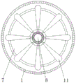
Fig. 1 is a schematic view of the front cross-sectional structure of the present invention;
fig. 2 is a schematic view of the overall structure of the mounting housing of the present invention;
FIG. 3 is a schematic top view of the cross-sectional structure of the present invention;
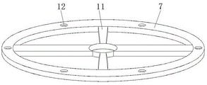
fig. 4 is a schematic view of the overall structure of the insulating housing of the present invention.
In the figure: 1. installing a shell; 2. heat dissipation holes; 3. a fixed block; 4. a connecting bolt; 5. a support block; 6. a clamping block; 7. an insulating housing; 8. a bearing; 9. mounting a column; 10. a threaded hole; 11. a silicon steel sheet body; 12. stabilizing the slot; 13. and (7) installing holes.
Detailed Description
The technical solutions in the embodiments of the present invention will be described clearly and completely with reference to the accompanying drawings in the embodiments of the present invention, and it is obvious that the described embodiments are only some embodiments of the present invention, not all embodiments. Based on the embodiments in the present invention, all other embodiments obtained by a person skilled in the art without creative work belong to the protection scope of the present invention.
Referring to fig. 1-4, the present invention provides a technical solution: a silicon steel sheet component for driving and radiating of an electric fan comprises a mounting shell 1, radiating holes 2, fixing blocks 3, connecting bolts 4, supporting blocks 5, clamping blocks 6, an insulating shell 7, a bearing 8, mounting columns 9, threaded holes 10, a silicon steel sheet body 11, stabilizing slots 12 and mounting holes 13, wherein the fixing blocks 3 are fixedly connected with the left end and the right end of the mounting shell 1, and the upper and lower single bodies of the fixing block 3 are fixedly connected with a connecting bolt 4 through a threaded hole 10, the upper and lower ends of the upper and lower single bodies of the mounting shell 1 are both provided with heat dissipation holes 2, and the inner wall of the mounting shell 1 is fixedly connected with a supporting block 5, the supporting block 5 is fixedly connected with a clamping block 6, the locking block 6 is connected with the stable slot 12 on the insulating housing 7 in a locking manner, the silicon steel sheet body 11 is fixedly installed inside the insulating housing 7, and the middle part of the silicon steel sheet body 11 is provided with a bearing 8, and one end of the mounting shell 1 far away from the heat dissipation hole 2 is fixedly connected with a mounting column 9.
Insulating casing 7 is the ring form structure as in fig. 1 and fig. 4, and insulating casing 7 is last to wait the angle and seted up stable slot 12, and it sets up to be one-to-one about stable slot 12 and the fixture block 6 between, it is firm on installation casing 1 to conveniently install insulating casing 7, facilitate the use, like the equal angle setting of erection column 9 in fig. 1 on installation casing 1, and connect for the block between erection column 9 and the mounting hole 13, and erection column 9 and mounting hole 13 set up on installation casing 1 at intervals, be convenient for support insulating casing 7, the fixed silicon steel sheet body 11 of easy to assemble, facilitate the use.
As shown in FIG. 1, FIG. 2 and FIG. 3, the silicon steel sheet body 11 is disposed on the insulating housing 7 at an equal angle, and the silicon steel sheet body 11 and the insulating housing 7 are integrally connected, so that ventilation and heat dissipation can be conveniently performed on the silicon steel sheet body 11 during operation, the service life of the silicon steel sheet body 11 can be conveniently prolonged, and the use is convenient.
The working principle is as follows: when the silicon steel sheet component for driving and radiating the electric fan is used, firstly, as shown in fig. 1 and fig. 4, the insulating shell 7 is clamped on the clamping block 6 through the stabilizing slot 12, so that the insulating shell 7 is installed in the installation shell 1 at the lower side, then the installation shell 1 at the upper side is clamped in the stabilizing slot 12 at the upper side of the insulating shell 7 through the clamping block 6, so that the supporting block 5 is convenient for supporting and clamping the insulating shell 7 for fixing, and preventing the insulating shell from falling off, the connecting bolt 4 is fixedly connected with the installation shell 1 through the fixing block 3 for completing the installation and the fixation of the insulating shell 7, as shown in fig. 2 and fig. 3, the silicon steel sheet body 11 is integrally connected in the insulating shell 7, the silicon steel sheet body 11 is arranged in the insulating shell 7 at equal angles, so that the rotating speed of fan blades installed on the bearing 8 is improved when the silicon steel sheet body 11, the silicon steel sheet assembly is convenient to use, meanwhile, the silicon steel sheet body 11 is conveniently subjected to heat dissipation treatment through the heat dissipation holes 2 formed in the mounting shell 1, the service life of the silicon steel sheet body 11 is prolonged, and the whole process of driving the heat dissipation silicon steel sheet assembly by the electric fan is realized.
Although embodiments of the present invention have been shown and described, it will be appreciated by those skilled in the art that changes, modifications, substitutions and alterations can be made in these embodiments without departing from the principles and spirit of the invention, the scope of which is defined in the appended claims and their equivalents.
Claims (6)
1. The utility model provides a be used for radiating blade of silicon steel subassembly of electric fan drive, is including installation shell (1), bearing (8) and blade of silicon steel body (11), its characterized in that: the mounting structure is characterized in that the mounting shell (1) is provided with a fixed block (3) at the left end and the right end, upper and lower monomers of the fixed block (3) are provided with connecting bolts (4) through threaded holes (10) in fixedly connected mode, heat dissipation holes (2) are formed in the upper and lower monomers of the mounting shell (1) in a clamped mode, inner wall fixedly connected with supporting blocks (5) of the mounting shell (1) are installed, fixedly connected with clamping blocks (6) are arranged on the supporting blocks (5), the clamping blocks (6) are connected with stabilizing slots (12) in the insulating shell (7) in a clamped mode, the insulating shell (7) is fixedly provided with a silicon steel sheet body (11), a bearing (8) is installed in the middle of the silicon steel sheet body (11), and one end fixedly connected with mounting columns (9) of the heat dissipation holes (.
2. A silicon steel sheet assembly for use in an electric fan for heat dissipation as defined in claim 1, wherein: the installation shell (1) is of a concave structure, the installation shell (1) is of a hollow cylinder structure, and the installation columns (9) fixedly connected to the installation shell (1) are arranged between the upper monomer and the lower monomer of the installation shell (1) in a staggered mode.
3. A silicon steel sheet assembly for use in an electric fan for heat dissipation as defined in claim 1, wherein: the thickness dimension of the wall thickness of the insulating shell (7) is equal to the length dimension of the supporting blocks (5), and the distance dimension of the supporting blocks (5) is not less than the thickness dimension of the insulating shell (7).
4. A silicon steel sheet assembly for use in an electric fan for heat dissipation as defined in claim 1, wherein: insulating casing (7) are the ring form structure, and wait for the angle on insulating casing (7) and seted up and stabilize slot (12) to be the one-to-one setting from top to bottom between stable slot (12) and fixture block (6).
5. A silicon steel sheet assembly for use in an electric fan for heat dissipation as defined in claim 1, wherein: the mounting columns (9) are arranged at equal angles on the mounting shell (1), the mounting columns (9) are connected with the mounting holes (13) in a clamping mode, and the mounting columns (9) and the mounting holes (13) are arranged on the mounting shell (1) at intervals.
6. A silicon steel sheet assembly for use in an electric fan for heat dissipation as defined in claim 1, wherein: the silicon steel sheet body (11) is arranged on the insulating shell (7) at an equal angle, and the silicon steel sheet body (11) and the insulating shell (7) are in an integrated connection structure.
Priority Applications (1)
| Application Number | Priority Date | Filing Date | Title |
|---|---|---|---|
| CN202021891965.1U CN212660010U (en) | 2020-09-02 | 2020-09-02 | Silicon steel sheet component for driving electric fan to dissipate heat |
Applications Claiming Priority (1)
| Application Number | Priority Date | Filing Date | Title |
|---|---|---|---|
| CN202021891965.1U CN212660010U (en) | 2020-09-02 | 2020-09-02 | Silicon steel sheet component for driving electric fan to dissipate heat |
Publications (1)
| Publication Number | Publication Date |
|---|---|
| CN212660010U true CN212660010U (en) | 2021-03-05 |
Family
ID=74761617
Family Applications (1)
| Application Number | Title | Priority Date | Filing Date |
|---|---|---|---|
| CN202021891965.1U Expired - Fee Related CN212660010U (en) | 2020-09-02 | 2020-09-02 | Silicon steel sheet component for driving electric fan to dissipate heat |
Country Status (1)
| Country | Link |
|---|---|
| CN (1) | CN212660010U (en) |
-
2020
- 2020-09-02 CN CN202021891965.1U patent/CN212660010U/en not_active Expired - Fee Related
Similar Documents
| Publication | Publication Date | Title |
|---|---|---|
| CN215580765U (en) | High-efficient heat dissipation motor | |
| CN111668969A (en) | High heat dissipation type sewing machine motor shell | |
| CN215292961U (en) | Wind tunnel simulation fan | |
| CN215212648U (en) | An assembled electric power tower | |
| CN118713382B (en) | Direct current motor with heat dissipation protective structure | |
| CN117748797A (en) | Explosion-proof motor with base heat dissipation mechanism | |
| CN207304221U (en) | A kind of motor housing | |
| CN209994168U (en) | Industrial ceiling fan | |
| CN111124091B (en) | CPU radiator | |
| CN215377542U (en) | Power battery system support | |
| CN216599180U (en) | Novel low-density anti-fatigue metal motor support | |
| CN213185730U (en) | Miniature motor capable of dissipating heat and cooling | |
| CN223908437U (en) | Pipeline fan | |
| CN221380720U (en) | Compressor motor stator assembly with improved structure | |
| CN219841596U (en) | Industrial air conditioner heat exchanger installation device | |
| CN222146971U (en) | A heat dissipation device for energy-saving weak current engineering distribution box | |
| CN218784010U (en) | DC power supply device convenient to install | |
| CN224054600U (en) | Frequency converter support structure | |
| CN219960322U (en) | High-precision thin-wall hollow precision motor | |
| CN220475329U (en) | Cable bracket convenient to fix cable | |
| CN218416114U (en) | Disc type motor stator | |
| CN216904462U (en) | Novel motor | |
| CN222169461U (en) | A compressor motor with insulation protection structure | |
| CN219953695U (en) | Axial flow impeller fan | |
| CN217590455U (en) | Motor casing |
Legal Events
| Date | Code | Title | Description |
|---|---|---|---|
| GR01 | Patent grant | ||
| GR01 | Patent grant | ||
| CF01 | Termination of patent right due to non-payment of annual fee |
Granted publication date: 20210305 |
|
| CF01 | Termination of patent right due to non-payment of annual fee |