Adjustable excircle boring cutter
Technical Field
The utility model belongs to the technical field of machining equipment and specifically relates to a boring cutter.
Background
The existing adjustable excircle boring cutter is limited by the bearing of a machine tool spindle, the structural optimization and weight reduction of the cutter are mainly considered in the design, the density and rigidity of a material are considered by selecting a cutter main body material, and a good vibration damping means is not provided.
The existing adjustable excircle boring cutter comprises a cutter handle, a cutter holder, a balancing weight, a cutter rod and a cutter fine-tuning unit, wherein the balancing weight and the cutter rod are respectively and symmetrically arranged at two ends of the cutter holder and are rigidly connected with the cutter holder, the cutter fine-tuning unit is fixedly arranged on the cutter rod, and the cutter handle is rigidly connected with the cutter holder. After the tool holder is connected with the rotating shaft of the boring machine, the tool holder is driven to rotate, and then the tool bit is driven to rotate, so that the workpiece is machined. Because all parts from the rotating shaft to the cutter are rigidly connected, when a workpiece is machined, the excircle boring cutter can generate large bending moment and torque at the connecting position of a machine tool spindle and the cutter under the machining state, the cutter is easily shaken under the influence of the tension of the machine tool spindle and the rigidity of a machine tool-cutter system, and the problems of cutter abrasion aggravation, part size instability and surface roughness overproof are caused.
SUMMERY OF THE UTILITY MODEL
The utility model aims to solve the technical problem that an adjustable excircle boring cutter that can alleviate vibration and machining precision is higher is provided.
The utility model provides a technical scheme that its technical problem adopted is: the utility model discloses a cutter body and handle of a knife, cutter body and handle of a knife are connected, the cutter body is rectangular shape, and it has the spout to open along cutter body length direction at the cutter body top, and the one end of spout is equipped with the balancing piece subassembly that there is the slider bottom, and the other end is equipped with the cutter fine setting unit subassembly that there is the slider bottom, slider and spout closely cooperate and form the direction cooperation, the spout bottom is equipped with the screw hole, it has rectangular through-hole to open on cutter fine setting unit subassembly and the balancing piece subassembly, and stretching screw passes rectangular through-hole and cutter body connection on the cutter fine setting unit subassembly, and stretching screw passes rectangular through-hole and cutter body connection on the balancing piece subassembly, sets up the damping.
Further, the material of the vibration damping block is foam metal or hard rubber, and the material of the cutter body is forged aluminum.
Further, the tool fine adjustment unit assembly and the balance weight assembly are symmetrically arranged relative to the rotation central axis of the tool holder.
Further, the cutter fine-tuning unit component is composed of a cutter fine-tuning unit, a cutter bar, a sliding block and a supporting seat in rigid connection, and the balance block component is composed of a balance block, a sliding block and a supporting seat in rigid connection.
Further, the foamed metal is foamed aluminum.
Further, the strip-shaped through holes are formed in the supporting seats, two strip-shaped through holes are formed in each supporting seat, and the strip-shaped through holes in each supporting seat are symmetrically arranged relative to the center line of the cutter body in the length direction; the balance weight and the cutter bar have the same weight and the same shape.
Furthermore, one end of the cutter rod, which is far away from the cutter body, is provided with an inclined mounting plane facing the balance block, and the cutter fine adjustment unit is mounted in the center of the mounting plane and is vertical to the mounting plane.
Further, the sliding blocks are respectively arranged on the other side of the supporting seat opposite to the cutter bar and the balance block.
Further, the balance block assembly and the cutter fine-tuning unit assembly are symmetrically arranged at two ends of the cutter body relative to the cutter body rotation axis.
Further, a notch is arranged at the top of the sliding groove at one end of the cutter fine adjustment unit assembly arranged on the cutter body, and a vibration reduction block is arranged in the notch.
Furthermore, the size of the vibration reduction block is the same as that of the notch, and the size of the vibration reduction block meets the requirement of the sliding stroke of the cutter fine adjustment unit component.
The utility model has the advantages that: compare with current adjustable excircle boring cutter, the utility model discloses be rigid connection between each spare part and not completely, but set up the damping piece that the material that has certain rigidity that can absorb the impact made between cutter body and cutter fine setting unit subassembly, the damping piece is when playing support cutter fine setting unit subassembly, when the processing work piece, can absorb the impact that comes from cutter and the production of lathe main shaft junction, thereby alleviate the impact that transmits the tool bit, finally alleviate the vibration of tool bit, thereby improve the machining precision and alleviate the wearing and tearing of cutter.
Drawings
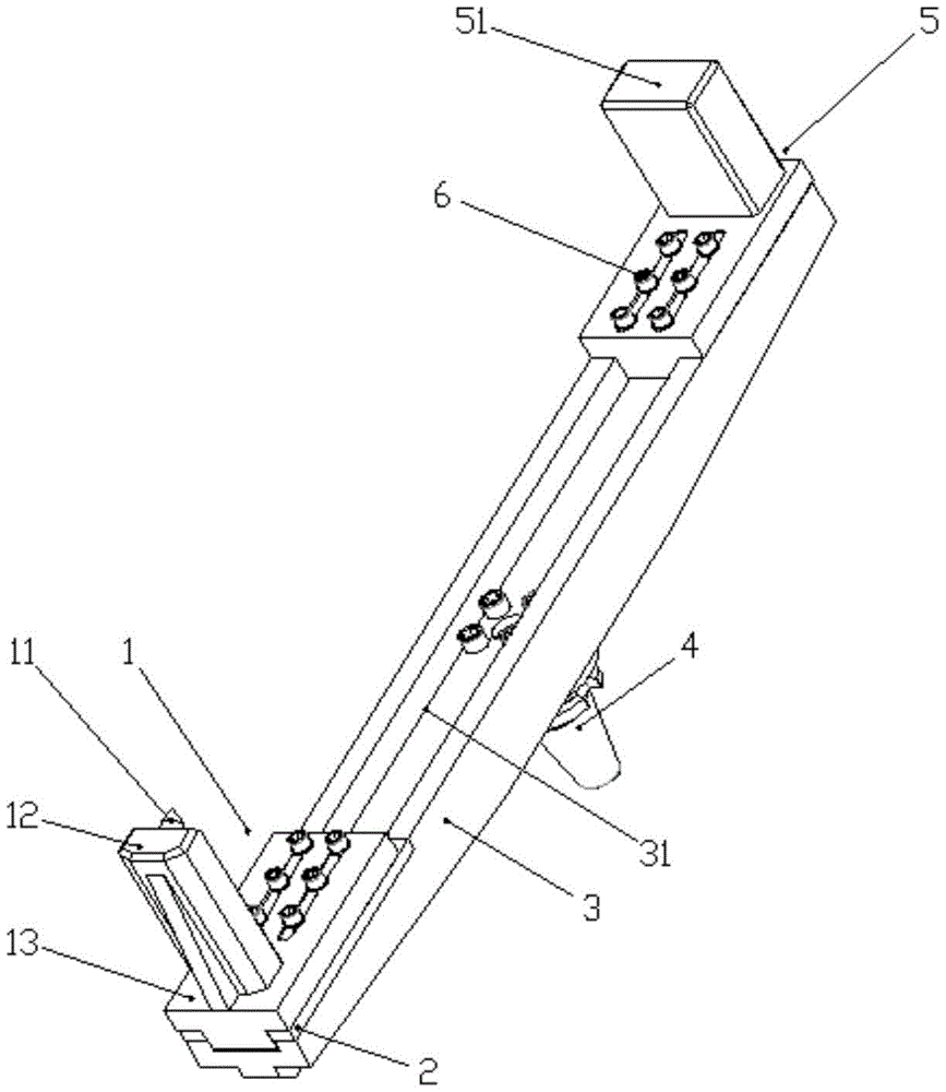
Fig. 1 is a perspective view of the assembled body of the present invention;
FIG. 2 is a schematic structural view of a balance block assembly;
FIG. 3 is a schematic view of a cutter body structure;
FIG. 4 is a schematic view of the tool fine adjustment unit assembly;
parts, positions and numbers in the drawings: the tool fine-tuning unit comprises a tool fine-tuning unit component 1, a tool fine-tuning unit 11, a tool bar 12, a supporting seat 13, a sliding block 14, a long through hole 15, a vibration reduction block 2, a tool body 3, a sliding groove 31, a notch 32, a tool shank 4, a balance block component 5, a balance block 51 and a tension screw 6.
Detailed Description
The following describes embodiments of the present invention with reference to the accompanying drawings.
As shown in fig. 1, the utility model discloses a cutter fine tuning unit subassembly 1, damping piece 2, cutter body 3, handle of a knife 4, balance block subassembly 5, tension screw 6, cutter body 3 is rectangular shape, handle of a knife 4 and cutter body 3 fixed connection, handle of a knife 4 is connected with the pivot axis of lathe, it is rotatory to drive cutter body 3, cutter fine tuning unit subassembly 1 and balance block subassembly 5 are arranged at the both ends of cutter body 4 length direction for the rotation axis symmetry of cutter body 3 and are connected with the screw hole on cutter body 3 through tension screw 6, adjust the distance between cutter fine tuning unit subassembly 1, the balance block subassembly 5 according to the size of the work piece of being processed, damping piece 2 sets up in breach 32 between fine tuning cutter unit subassembly 1 and the cutter body, and compressed tightly on cutter body 3; the mode of not arranging the notch 32 can also be adopted, and only the vibration reduction block 2 and the cutter fine adjustment unit assembly 1 are rigidly connected to form an integrated component.
The cutter fine-tuning unit component 1 consists of a cutter fine-tuning unit 11, a cutter bar 12 and a supporting seat 13, can slide along the length direction of the cutter body 3, and can adjust the size of a machined excircle. The cutter fine-tuning unit 11 is in the prior art and can adjust the angle of a cutter head; the top end of the cutter bar 12 far away from the supporting seat 13 is provided with an inclined mounting plane facing the balance block 51, and the cutter fine adjustment unit 11 is vertically mounted in the center of the mounting plane through a screw; the cutter bar 12 and the supporting seat 13 are rigidly connected by welding and the like, a convex sliding block 14 is arranged on the other surface of the supporting seat 13 opposite to the cutter bar 12, the sliding block 14 can be one of rectangular or dovetail-shaped in cross section, and the sliding block 14 and a sliding groove 31 at the top of the cutter body 3 form guiding fit; the width of the supporting seat 13 is the same as that of the cutter body 3, two strip through holes 15 are formed in the supporting seat 13, the tensioning screws 6 can penetrate through the through holes and can move relatively in the through holes, and the strip through holes 15 are symmetrically arranged relative to the central line of the cutter body 3 in the length direction.
The vibration damping block 2 is made of a material with strong impact absorption capability, is in a strip shape, and is preferably a material with low density and high strength and rigidity so as to provide sufficient support for the tool fine adjustment unit assembly 1 while reducing the weight, one of hard rubber or foam metal is adopted, the preferred material is foam metal, the foam metal material has excellent impact energy absorption characteristics, particularly foam aluminum, and the length of the vibration damping block 2 is at least half of the processing size adjustment range more than the length of the supporting seat 13 so as to meet the requirement of the sliding stroke of the assembly.
The top of the cutter body 3 is provided with a sliding groove 31 along the length direction, the section shape of the sliding groove 31 is matched with that of the sliding block 14, threaded holes with uniform intervals are arranged at two ends of the bottom of the sliding groove 31, the threaded holes are symmetrically arranged relative to the center line of the cutter body in the width direction, a notch 31 is formed at one end of the sliding groove 31, which is provided with the cutter fine-tuning unit assembly 1, the size of the notch 31 is the same as that of the vibration damping block 2, and a key groove and a through hole which are matched with the cutter handle 4 are formed in the; under the condition of meeting the strength requirement, the cutter body 3 removes partial materials relative to the back of the chute 31 so as to save materials and reduce weight; the cutter body 3 is preferably made of a solid material with low density and high rigidity and strength, and is preferably made of forged aluminum.
Handle of a knife 4 is the standard component, belongs to prior art, is connected fixedly through screw and key and cutter body 3, and the transmission comes the moment of torsion of lathe rotation axis for the cutter body.
The balance block assembly 5 comprises a balance block 51 and a support base 13 and can slide along the length direction of the cutter body 3, the shape and the weight of the balance block 51 are the same as those of the cutter rod 12, the balance block 51 is rigidly connected with the support base 13 in a welding mode and the like, a convex sliding block 14 is arranged on the other side, opposite to the balance block 51, of the support base 3, the cross section of the sliding block 14 is the same as that of the cutter fine adjustment unit assembly 1, and the balance block assembly 5 and the cutter fine adjustment unit assembly 1 are symmetrically arranged relative to the rotation central axis of the cutter body 3 so as to enable the center of mass of the.
The tensioning screw 6 is matched with the connecting threaded hole of the cutter handle 4 so as to improve the universality among parts.