CN212628380U - Sound box with good playing tone quality effect - Google Patents
Sound box with good playing tone quality effect Download PDFInfo
- Publication number
- CN212628380U CN212628380U CN202021868665.1U CN202021868665U CN212628380U CN 212628380 U CN212628380 U CN 212628380U CN 202021868665 U CN202021868665 U CN 202021868665U CN 212628380 U CN212628380 U CN 212628380U
- Authority
- CN
- China
- Prior art keywords
- box
- loudspeaker
- sound
- full
- window
- Prior art date
- Legal status (The legal status is an assumption and is not a legal conclusion. Google has not performed a legal analysis and makes no representation as to the accuracy of the status listed.)
- Active
Links
- 230000000694 effects Effects 0.000 title claims abstract description 23
- 229920000742 Cotton Polymers 0.000 claims description 8
- 238000009434 installation Methods 0.000 claims description 7
- 230000000149 penetrating effect Effects 0.000 claims description 4
- 238000009413 insulation Methods 0.000 claims description 3
- 230000002349 favourable effect Effects 0.000 abstract description 5
- CJDNEKOMKXLSBN-UHFFFAOYSA-N 1-chloro-3-(4-chlorophenyl)benzene Chemical compound C1=CC(Cl)=CC=C1C1=CC=CC(Cl)=C1 CJDNEKOMKXLSBN-UHFFFAOYSA-N 0.000 description 10
- 230000006870 function Effects 0.000 description 3
- 238000007789 sealing Methods 0.000 description 3
- 238000012986 modification Methods 0.000 description 2
- 230000004048 modification Effects 0.000 description 2
- 230000006978 adaptation Effects 0.000 description 1
- 230000009286 beneficial effect Effects 0.000 description 1
- 238000010586 diagram Methods 0.000 description 1
- 230000008034 disappearance Effects 0.000 description 1
- 238000005516 engineering process Methods 0.000 description 1
- 230000005669 field effect Effects 0.000 description 1
- 238000000034 method Methods 0.000 description 1
- 125000006850 spacer group Chemical group 0.000 description 1
Images


Landscapes
- Obtaining Desirable Characteristics In Audible-Bandwidth Transducers (AREA)
Abstract
The utility model discloses a sound box with good effect of playing sound quality, which comprises a box body, and a heavy woofer, a full-frequency horn and an inverted phase tube which are arranged on the box body; the box body is internally provided with an accommodating cavity, and the full-frequency loudspeakers are respectively arranged on the left side and the right side of the subwoofer; the sound outlet end of the subwoofer is arranged upwards; one end of the phase inverter tube is connected with the area where the subwoofer is located, and the other end of the phase inverter tube is arranged forwards; the sound outlet end of the full-frequency loudspeaker is arranged forwards; so, through the design of arranging of heavy woofer and full loudspeaker, utilize heavy woofer to go out the sound up, full loudspeaker go out the sound forward, in order to realize that the audio amplifier produces the effect of encircleing the audio, and, the setting of paraphase pipe, the bass that vibrations produced in the cavity with heavy woofer is poured forward through the paraphase pipe, make the heavy bass effect of audio amplifier better, structural design is simple, and is ingenious reasonable, be favorable to improving the broadcast tone quality of audio amplifier, experience for the better audio of user.
Description
Technical Field
The utility model relates to a sound box field technique especially indicates a sound box that broadcast tone quality effect is good.
Background
Along with the development of science and technology, the living standard of people is improved, and entertainment and leisure are more and more valued by society, so that a lot of business opportunities are brought; the sound box is used as an output terminal of the sound equipment, mainly has the function of converting the electric signal into sound through the loudspeaker, and restores the sound into a field effect as much as possible by means of the sound assisting function of the sound box; the sound box usually comprises a heavy woofer and a full-frequency loudspeaker, and the sound box can generate surround sound effect by the combined playing of the heavy woofer and the full-frequency loudspeaker, so that better hearing experience is brought; however, the sound outlet ends of the existing subwoofer and the full-frequency speaker are all arranged in the same direction, so that the surrounding sound effect of the sound box is poor, the sound effect is limited, and the application range is small.
Therefore, a new technical solution is needed to solve the above problems.
Disclosure of Invention
In view of this, the utility model discloses to the disappearance that prior art exists, its main objective is to provide a good audio amplifier of broadcast tone quality effect, it is through the design of arranging of heavy woofer and full loudspeaker all around to realize that the audio amplifier produces the effect of encircleing the audio, and, the setting of paraphase pipe, pour the bass that heavy woofer vibrations produced in the cavity forward through the paraphase pipe, make the heavy bass effect of audio amplifier better, the broadcast tone quality of audio amplifier has been improved, experience for the better audio of user.
In order to achieve the above purpose, the utility model adopts the following technical scheme:
a sound box with good playing tone quality effect comprises a box body, a heavy woofer, a full-frequency horn and an inverter tube, wherein the heavy woofer, the full-frequency horn and the inverter tube are arranged in the box body; wherein:
the box body is internally provided with an accommodating cavity, and the full-frequency loudspeakers are respectively arranged on the left side and the right side of the subwoofer; the sound outlet end of the subwoofer is arranged upwards; one end of the phase inverter tube is connected with the area where the subwoofer is located, and the other end of the phase inverter tube is arranged forwards; the sound outlet end of the full-frequency loudspeaker is arranged forwards;
two sound insulation plates which are arranged in a left-right spacing mode are arranged in the accommodating cavity so as to divide the accommodating cavity into a left cavity, a middle cavity and a right cavity which are arranged in sequence from left to right; full frequency loudspeaker set up respectively in left side cavity, right side cavity, heavy woofer and paraphase pipe all are located middle cavity.
As a preferred scheme, a first window penetrating through the accommodating cavity is formed in the top end of the box body, the heavy woofer is mounted on the first window and extends into the accommodating cavity, a second window and a third window are formed in the front end of the box body, the full-frequency horn is mounted on the second window and extends into the accommodating cavity, and the front end of the phase reversal pipe is mounted on the third window.
Preferably, the inverter tube comprises a straight tube part and an elbow part, the straight tube part extends from left to right, the elbow part extends obliquely forwards from one end of the straight tube part, and the front end of the elbow part is provided with an installation part to be connected to the periphery of a third window at the front end of the box body.
Preferably, the included angle between the straight pipe part and the bent pipe part is 120-130 degrees.
As a preferable scheme, the two heavy woofers are respectively arranged close to the left chamber and the right chamber; the inverter tube is located between the two subwoofers.
As a preferred scheme, full frequency loudspeaker are provided with four, and left side cavity, right side cavity respectively are provided with two.
As a preferred scheme, the front side of box is provided with the front shroud, encloses between front shroud and box front end and constitutes the antetheca, the antetheca is provided with soundproof cotton, soundproof cotton corresponds and sets up between heavy woofer, full frequency loudspeaker.
As a preferred scheme, the box body comprises a main shell body and side plates, wherein the main shell body is integrally connected with the side plates, and the side plates are arranged at the left end and the right end of the main shell body respectively; the first window, the second window and the third window are respectively arranged on the main shell.
As an optimal scheme, the subwoofer has a horn frame that supplies it to install, the horn frame is installed in first window department, the horn frame is provided with the spliced pole, the spliced pole extends down and supports and locate holding intracavity bottom, corresponding first connecting hole, second connecting hole have been seted up respectively to box and spliced pole to connect gradually in first connecting hole, second connecting hole through first connecting piece in the bottom of box to reach the installation location of subwoofer in the box.
Compared with the prior art, the utility model have obvious advantage and beneficial effect, particularly, can know by above-mentioned technical scheme, it mainly is through the design of arranging of heavy woofer and full loudspeaker, utilize heavy woofer to go out the sound up, full loudspeaker go out the sound forward, in order to realize that the audio amplifier produces the effect of encircleing the audio, and, the setting of paraphase pipe, pour the bass that vibrations produced heavy woofer in the cavity through the paraphase pipe, make the heavy bass effect of audio amplifier better forward, structural design is simple, and is ingenious reasonable, be favorable to improving the broadcast tone quality of audio amplifier, experience for the better audio of user.
To illustrate the structural features and functions of the present invention more clearly, the present invention will be described in detail with reference to the accompanying drawings and specific embodiments.
Drawings
Fig. 1 is a first perspective view of an embodiment of the present invention;
fig. 2 is a second perspective view of the embodiment of the present invention;
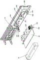
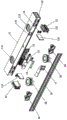
fig. 3 is a first exploded view of an embodiment of the present invention;
fig. 4 is an exploded view of a speaker unit according to an embodiment of the present invention;
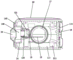
fig. 5 is a first cross-sectional view of an embodiment of the invention;
fig. 6 is a second cross-sectional view of an embodiment of the invention;
fig. 7 is an exploded view of a PCB board, cover and mounting member of an embodiment of the invention;
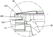
fig. 8 is a third cross-sectional view of an embodiment of the invention;
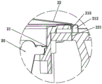
fig. 9 is a fourth cross-sectional view of an embodiment of the invention;
fig. 10 is a second exploded view of an embodiment of the present invention;
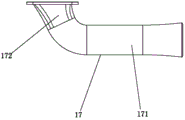
FIG. 11 is a schematic diagram of an inverter according to an embodiment of the present invention.
The attached drawings indicate the following:
10. case 101, first connecting hole
102. Third connecting hole 11, main casing
111. The accommodating cavity 112 and the first window
113. Second window 114, front cavity
115. Third Window 116, baffle
117. Fourth window 12, side plate
121. Key 13 and PCB
131. Extension 132, spacer
133. Data interface 14, mounting bracket
141. Opening 142 and first connecting part
143. Second connecting part 144 and positioning groove
145. Fixed edge 146, groove
147. Convex strip 148 and switch
15. Sealing cover 151 and sealed space
16. Ear hanging part 17, inverter tube
171. Straight pipe 172 and bent pipe
18. Front cover 20, heavy woofer
201. Second positioning portion 202, fourth connecting hole
21. Speaker frame 211, connecting column
212. Mounting and positioning edge 213 and first positioning part
214. Concave position 215 and clamping hole
216. Second and fifth connection holes 217 and 217
22. Net cover 221, snap projection
30. Full frequency loudspeaker.
Detailed Description
Fig. 1 to 11 show specific structures of embodiments of the present invention.
A sound box with good playing tone quality effect comprises a box body 10, a heavy woofer 20, a full-frequency loudspeaker 30 and an inverter tube 17, wherein the heavy woofer 20, the full-frequency loudspeaker 30 and the inverter tube 17 are arranged on the box body 10; wherein:
the box body 10 is provided with an accommodating cavity 111, and the full-frequency speakers 30 are respectively arranged at the left side and the right side of the subwoofer 20; the sound outlet end of the subwoofer 20 is arranged upwards; one end of the phase inverter tube 17 is connected with the area where the subwoofer 20 is located, and the other end of the phase inverter tube 17 is arranged forwards; the sound outlet end of the full-frequency loudspeaker 30 is arranged forwards; so, utilize the heavy woofer to go out the sound up, full frequency loudspeaker go out the sound forward to realize that the audio amplifier produces the effect of encircleing the audio, just, the setting of inverted phase pipe pours the bass that heavy woofer vibrations produced in the cavity through inverted phase pipe forward, makes the heavy bass effect of audio amplifier better, has improved the broadcast tone quality of audio amplifier, gives the better audio experience of user.
Generally, two sound insulation boards 116 are arranged in the accommodating cavity 111 in a left-right spacing manner, so as to divide the accommodating cavity 111 into a left chamber, a middle chamber and a right chamber which are arranged in sequence from left to right; the full-frequency horn 30 is respectively arranged in the left cavity and the right cavity, and the heavy bass horn 20 and the phase-reversing tube 17 are both located in the middle cavity.
As shown in fig. 10, in the present embodiment, two subwoofers 20 are provided, which are respectively disposed near the left chamber and the right chamber; the inverter tube 17 is located between the two subwoofers 20; and, the full frequency horn 30 is provided with four, and the left side cavity, the right side cavity respectively are provided with two.
As shown in fig. 10, a first window 112 penetrating through the accommodating cavity 111 is formed at the top end of the box body 10, the subwoofer 20 is mounted on the first window 112 and extends into the accommodating cavity 111, a second window 113 and a third window 115 are formed at the front end of the box body 10, the full-frequency speaker 30 is mounted on the second window 113 and extends into the accommodating cavity 111, and the front end of the inverter tube 17 is mounted on the third window 115.
As shown in fig. 11, the inverter tube 17 includes a straight tube portion 171 and an elbow portion 172, the straight tube portion 171 extends left and right, the elbow portion 172 extends obliquely forward integrally at one end of the straight tube portion 171, and the front end of the elbow portion 172 is provided with a mounting portion to be connected to the periphery of the front third window 115 of the casing 10; here, the included angle between the straight pipe portion 171 and the bent pipe portion 172 is 120-130 degrees; preferably, the included angle between the straight pipe portion 171 and the bent pipe portion 172 is 126 degrees.
As shown in fig. 10, a front cover 18 is disposed at the front side of the cabinet 10, a front cavity 114 is defined between the front cover 18 and the front end of the cabinet 10, and soundproof cotton is disposed in the front cavity 114 and correspondingly disposed between the subwoofer 20 and the full-band speaker 30; therefore, the bass generated by the heavy bass loudspeaker in the middle cavity is prevented from being overlapped with the sound of the full-frequency loudspeaker when being transmitted forwards from the phase-reversing tube, and the tone quality effect when the loudspeaker box is played is ensured.
In addition, the box body 10 includes a main housing 11 integrally connected with each other and a side plate 12 disposed on the main housing 11, the accommodating cavity 111 is formed in the main housing 11, and the side plates 12 are respectively disposed at the left and right ends of the main housing 11 to close the accommodating cavity 111; the first window 112, the second window 113 and the third window 115 are respectively arranged on the main shell 11; preferably, the side plate 12 on the left side is provided with keys 121, the keys 121 are arranged in a front-back spacing manner, and the keys 121 are connected to the PCB 13; and, be provided with the hangers portion 16 on the main casing body 11, hangers portion 16 is provided with two, and two hangers portions 16 are left-right interval formula and are arranged in the rear end of main casing body 11.
As shown in fig. 3, 4 and 5, the subwoofer 20 has a speaker frame 21 for the subwoofer to be installed, the speaker frame 21 is installed at the first window 112, the speaker frame 21 is provided with a connection post 211, the connection post 211 extends downward and abuts against the bottom end of the accommodating cavity 111, the box body 10 and the connection post 211 are respectively provided with a first connection hole 101 and a second connection hole 216, and the bottom end of the box body 10 is sequentially connected to the first connection hole 101 and the second connection hole 216 through a first connection member, so as to achieve the installation and positioning of the subwoofer 20 in the box body 10.
As shown in fig. 5 and 8, the horn holder 21 has a mounting and positioning edge 212, and the mounting and positioning edge 212 is located outside the top end of the box body 10; here, the four connecting columns 211 are located at the lower end of the mounting and positioning edge 212; moreover, a third connecting hole 102 is arranged at the top end of the box body 10 corresponding to the periphery of the first window 112, the mounting and positioning edge 212 is provided with a first positioning portion 213, the first positioning portion 213 is located at the lower end of the mounting and positioning edge 212, and the first positioning portion 213 is limited in the third connecting hole 102, so as to realize the positioning between the horn frame 21 and the first window 112; so, the setting on installation location limit has made things convenient for the location between loudspeaker frame and the box, and simultaneously, the setting of first location portion and third connecting hole utilizes first location portion to be restricted in the third connecting hole to realize that loudspeaker frame is connected with the location of first window, the location is accurate, and the equipment is convenient.
As shown in fig. 4, the horn frame 21 has a concave portion 214 extending downward, a through hole is formed in the concave portion 214, a second positioning portion 201 extends from the periphery of the subwoofer 20, the subwoofer 20 extends into the through hole from top to bottom, and the second positioning portion 201 abuts against an inner end surface of the concave portion 214 and is fixed to form an assembling location of the subwoofer 20; here, the second positioning portion 201 and the recess 214 are respectively provided with a fourth connecting hole 202 and a fifth connecting hole 217, and the second positioning portion 201 is sequentially connected to the fourth connecting hole 202 and the fifth connecting hole 217 through a second connecting member, so as to achieve the assembling and positioning between the subwoofer 20 and the speaker frame 21.
In addition, a mesh enclosure 22 is arranged on the outer side of the horn frame 21, the mesh enclosure 22 is assembled on the horn frame 21 in a buckling manner, and the mesh enclosure 22 covers the installation positioning edge 212 of the horn frame 21; here, the mesh enclosure 22 has the protruding 221 of card that downwardly extending set up, the protruding 221 of card is provided with four, and four protruding 221 of card are arranged along the lower extreme periphery interval formula of mesh enclosure, the protruding 221 of card that the mesh enclosure 22 is corresponding to the loudspeaker frame 21 is provided with card hole 215, protruding 221 adaptations of card are located in card hole 215 to form the assembly connection between mesh enclosure 22 and the loudspeaker frame 21.
The portable electronic device is characterized by further comprising a PCB 13 and a cover 15, wherein the PCB 13 and the cover 15 are both arranged in the accommodating cavity 111, the PCB 13 is connected with a mounting rack 14, the box body 10 is provided with a fourth window 117 penetrating through the accommodating cavity 111, the mounting rack 14 is mounted on the fourth window 117 and extends into the accommodating cavity 111, the PCB 13 is provided with a plurality of data interfaces 133 arranged at intervals, the mounting rack 14 is provided with openings 141, and the data interfaces 133 are exposed out of the corresponding openings 141;
the cover 15 is covered on the PCB 13 and fixed on the mounting frame 14, a sealed space 151 is formed between the cover 15 and the PCB 13 as well as between the cover 15 and the mounting frame 14, and the data interface 133 is located in the sealed space 151; so, utilize to form confined space between lid and PCB board, the mounting bracket, avoided the sound in sound chamber to pass to the outside in data interface's gap, structural design is simple, and is ingenious reasonable, is favorable to having improved the broadcast tone quality of audio amplifier, and application scope is wide.
Preferably, soundproof cotton is arranged in the sealed space 15, and the soundproof cotton is arranged around the data interface 133; so, soundproof cotton's setting has further guaranteed the syllable-dividing effect of confined space, is favorable to improving the tone quality of audio amplifier, and the usability is good.
As shown in fig. 7, the mounting frame 14 is provided with first connecting portions 142 extending towards the PCB 13, two first connecting portions 142 are provided, two first connecting portions 142 are arranged on the mounting frame 14 at intervals, positioning grooves 144 are provided on opposite sides between the two first connecting portions 142, two ends of the PCB 13 are provided with extending portions 131 extending outwards, and the extending portions 131 are confined in the corresponding positioning grooves 144;
the PCB mounting structure is further provided with a gasket 132, the gasket 132 is respectively abutted to the end portions of the first connecting portion 142 and the extending portion 131, the first connecting portion 142 and the gasket 132 are respectively provided with a corresponding sixth connecting hole and a corresponding seventh connecting hole, and the first connecting portion 142 and the gasket 132 are sequentially connected to the seventh connecting hole and the sixth connecting hole through a third connecting piece, so that the assembling and positioning between the PCB 13 and the mounting frame 14 are achieved.
Here, the mounting frame 14 is provided with a second connecting portion 143 extending towards the cover 15, the second connecting portion 143 is located in the sealing space 151, and an end of the second connecting portion 143 abuts against the sealing cover 15 and is locked by a fourth connecting member.
As shown in fig. 7, a fixed edge 145 is disposed on the periphery of the mounting frame 14, the fixed edge 145 abuts against the edge of the second window 113, eighth connection holes are disposed on both the fixed edge 145 and the box body 10, and the fixed edge 145 and the box body 10 are sequentially connected to the fixed edge 145 and the eighth connection holes of the box body 10 through a fifth connection piece to form an assembly connection between the mounting frame 14 and the box body 10; preferably, a groove 146 is arranged on the outer side of the mounting rack 14, and the opening 141 is arranged on the inner end surface of the groove 146; moreover, a rib 147 for positioning the cover 15 is disposed on the mounting frame 14, the rib 147 extends along the outer periphery of the cover 15, the rib 147 is located above the opening 141, and the outer periphery of the cover 15 is limited by the lower end of the rib 147.
A switch 148 is also provided, the switch 148 being disposed within the recess 146 and laterally of the opening 141.
The utility model discloses a design is key, it is mainly through the design of arranging of heavy woofer and full loudspeaker, utilize heavy woofer to go out the sound up, full loudspeaker go out the sound forward, in order to realize that the audio amplifier produces the effect of encircleing the audio, and, the setting of paraphase pipe, pour the bass that heavy woofer vibrations produced forward through the paraphase pipe in the cavity, make the heavy bass effect of audio amplifier better, structural design is simple, it is ingenious reasonable, be favorable to having improved the broadcast tone quality of audio amplifier, experience for the better audio of user.
The above description is only a preferred embodiment of the present invention, and is not intended to limit the technical scope of the present invention, so that any slight modifications, equivalent changes and modifications made by the technical spirit of the present invention to the above embodiments are all within the scope of the technical solution of the present invention.
Claims (9)
1. The utility model provides a good audio amplifier of broadcast tone quality effect which characterized in that: comprises a box body, a heavy woofer, a full-frequency horn and an inverted tube, wherein the heavy woofer, the full-frequency horn and the inverted tube are arranged in the box body; wherein:
the box body is internally provided with an accommodating cavity, and the full-frequency loudspeakers are respectively arranged on the left side and the right side of the subwoofer; the sound outlet end of the subwoofer is arranged upwards; one end of the phase inverter tube is connected with the area where the subwoofer is located, and the other end of the phase inverter tube is arranged forwards; the sound outlet end of the full-frequency loudspeaker is arranged forwards;
two sound insulation plates which are arranged in a left-right spacing mode are arranged in the accommodating cavity so as to divide the accommodating cavity into a left cavity, a middle cavity and a right cavity which are arranged in sequence from left to right; full frequency loudspeaker set up respectively in left side cavity, right side cavity, heavy woofer and paraphase pipe all are located middle cavity.
2. The loudspeaker box of claim 1, wherein the sound box has an excellent playing quality, and the loudspeaker box comprises: the top end of the box body is provided with a first window penetrating through the accommodating cavity, the subwoofer is arranged on the first window and extends into the accommodating cavity, the front end of the box body is provided with a second window and a third window, the full-frequency horn is arranged on the second window and extends into the accommodating cavity, and the front end of the inverter tube is arranged on the third window.
3. The loudspeaker box of claim 2, wherein the sound box has an excellent playing quality: the inverted tube comprises a straight tube portion and an elbow portion, the straight tube portion extends leftwards and rightwards, the elbow portion extends forwards in an integrated inclined mode at one end of the straight tube portion, and the front end of the elbow portion is provided with an installation portion to be connected to the periphery of a front end third window of the box body.
4. A loudspeaker according to claim 3, wherein said loudspeaker has an excellent sound quality: the included angle between the straight pipe part and the bent pipe part is 120-130 degrees.
5. The loudspeaker box of claim 1, wherein the sound box has an excellent playing quality, and the loudspeaker box comprises: the two heavy woofers are respectively arranged close to the left cavity and the right cavity; the inverter tube is located between the two subwoofers.
6. The loudspeaker box of claim 1, wherein the sound box has an excellent playing quality, and the loudspeaker box comprises: the full-frequency horn is provided with four, and the left side cavity and the right side cavity are respectively provided with two.
7. The loudspeaker box of claim 1, wherein the sound box has an excellent playing quality, and the loudspeaker box comprises: the front side of box is provided with the front shroud, encloses between front shroud and box front end and constitutes the ante-chamber, be provided with soundproof cotton in the ante-chamber, soundproof cotton corresponds and sets up between heavy woofer, full-frequency loudspeaker.
8. The loudspeaker box of claim 2, wherein the sound box has an excellent playing quality: the box body comprises a main shell body and side plates, wherein the main shell body is integrally connected with the side plates, and the side plates are arranged on the left end and the right end of the main shell body respectively; the first window, the second window and the third window are respectively arranged on the main shell.
9. The loudspeaker box of claim 2, wherein the sound box has an excellent playing quality: heavy woofer has the loudspeaker frame that supplies it to install, loudspeaker frame is installed in first window department, loudspeaker frame is provided with the spliced pole, the spliced pole extends down and supports and locate holding intracavity bottom, corresponding first connecting hole, second connecting hole have been seted up respectively to box and spliced pole to connect gradually in first connecting hole, second connecting hole in the bottom of box through first connecting piece, in order to reach the installation location of heavy woofer in the box.
Priority Applications (1)
| Application Number | Priority Date | Filing Date | Title |
|---|---|---|---|
| CN202021868665.1U CN212628380U (en) | 2020-09-01 | 2020-09-01 | Sound box with good playing tone quality effect |
Applications Claiming Priority (1)
| Application Number | Priority Date | Filing Date | Title |
|---|---|---|---|
| CN202021868665.1U CN212628380U (en) | 2020-09-01 | 2020-09-01 | Sound box with good playing tone quality effect |
Publications (1)
| Publication Number | Publication Date |
|---|---|
| CN212628380U true CN212628380U (en) | 2021-02-26 |
Family
ID=74704608
Family Applications (1)
| Application Number | Title | Priority Date | Filing Date |
|---|---|---|---|
| CN202021868665.1U Active CN212628380U (en) | 2020-09-01 | 2020-09-01 | Sound box with good playing tone quality effect |
Country Status (1)
| Country | Link |
|---|---|
| CN (1) | CN212628380U (en) |
-
2020
- 2020-09-01 CN CN202021868665.1U patent/CN212628380U/en active Active
Similar Documents
| Publication | Publication Date | Title |
|---|---|---|
| CN211321501U (en) | speaker box | |
| CN101588395A (en) | Electronic device with loudspeaker | |
| CN111131980A (en) | Speaker modules and electronics | |
| CN212628369U (en) | Sound production device | |
| CN211909085U (en) | Microphone multichannel integrated equipment | |
| CN109040926A (en) | Microphone device and portable terminal | |
| CN210093517U (en) | Loudspeaker box | |
| CN216122887U (en) | Sound production device and electronic equipment | |
| CN211656330U (en) | Loudspeaker mounting structure | |
| CN209283447U (en) | earbuds | |
| CN216357143U (en) | Sound box equipment | |
| CN214205779U (en) | Multifunctional installation sound equipment | |
| CN212628371U (en) | Sound production device | |
| CN211656329U (en) | Sound box capable of preventing sound leakage of cavity | |
| CN210016620U (en) | Loudspeaker box | |
| CN216057394U (en) | Bar-shaped sound box and display device | |
| CN215581563U (en) | Split type bar audio amplifier | |
| CN2416701Y (en) | Improved full-range speakers | |
| CN203086656U (en) | Miniature flat-panel speaker | |
| CN215529218U (en) | Stereo set hole, stereo set subassembly and blank all-in-one | |
| CN216134563U (en) | Bar-shaped sound box and display device | |
| CN216057392U (en) | Bar-shaped sound box and display device | |
| CN216391343U (en) | Sound box more reasonable in assembly | |
| CN221151511U (en) | Ultrathin sounded air guide pipe structure | |
| CN223428528U (en) | A sound bar with horn speaker structure |
Legal Events
| Date | Code | Title | Description |
|---|---|---|---|
| GR01 | Patent grant | ||
| GR01 | Patent grant |