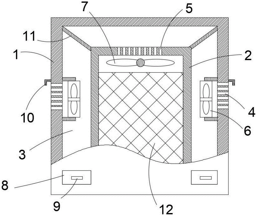
Power control cabinet of high security
Technical Field
The utility model relates to a power control cabinet of high security relates to regulator cubicle technical field.
Background
The power control cabinet is a cabinet which is formed by processing steel materials and used for protecting components from working normally. The power control cabinet is made of two materials, namely a hot-rolled steel plate and a cold-rolled steel plate. The cold-rolled steel sheet is softer than hot-rolled steel sheet, more is fit for the preparation of power switch board. The extensive mainly used chemical industry of power control cabinet usage, the environmental protection trade, electric power system, metallurgical system, industry, nuclear power industry, fire control safety control, traffic industry and so on, power control cabinet is at the practical application in-process, because inside electrical equipment operation leads to giving out a lot of heats, therefore need set up a plurality of louvres on the cabinet body, however, the louvre can lead to dust or rainwater to get into, therefore can influence the normal operating of regulator cubicle, security greatly reduced.
SUMMERY OF THE UTILITY MODEL
The utility model discloses the technical problem that will solve is: the power control cabinet effectively improves the safety of the cabinet body.
In order to solve the technical problem, the utility model discloses a realize through following technical scheme:
the utility model provides a power control cabinet of high security, includes the first cabinet body and the second cabinet body, the second cabinet position is in the internal portion of first cabinet, supports between the front and back side and the bottom of the external wall of first cabinet body and second cabinet and leans on sealing contact, controls and has the heat dissipation clearance between side and the top, and electrical control equipment installs internally in the second cabinet, it has a plurality of first louvres to open on the cabinet wall of the both sides of the first cabinet body, the top of the second cabinet body is equipped with a plurality of second louvres.
Preferably, the first heat dissipation hole side of the two sides of the first cabinet body is provided with a first exhaust fan, the first exhaust fan is installed in the heat dissipation gap and connected to the inner wall of the first cabinet body through a support, the top of the second cabinet body is provided with a second exhaust fan, and the second exhaust fan is installed below the second heat dissipation hole.
Preferably, a storage device for storing rainwater or dust is arranged at the bottom of the heat dissipation gap.
Preferably, the storage device is a drawer-type storage box, and an opening for the drawer-type storage box to enter and exit is provided at a corresponding position outside the first cabinet.
Preferably, the outer side box plate of the drawer type storage box is provided with a handle.
Preferably, a waterproof cover fixed on the outer wall of the first cabinet body is arranged above the outer hole of the first heat dissipation hole.
Preferably, the outer wall surface of the second cabinet body is coated with a waterproof coating.
Preferably, a filter screen is arranged in an airflow circulation gap between the first heat dissipation hole and the second heat dissipation hole.
Compared with the prior art, the utility model discloses an useful part is: the power control cabinet of high security simple structure, the installation preparation is convenient, through setting up the double-deck cabinet body, reserves the heat dissipation clearance, effectively improves the radiating effect of switch board then and avoids dust and rainwater directly to enter into the internal of cabinet to effectively improve the security of switch board, avoid dust and rainwater to influence the normal operating of inside equipment, therefore the practicality is high.
Description of the drawings:
in order to more clearly illustrate the technical solutions in the embodiments of the present invention, the drawings needed to be used in the embodiments will be briefly described below, and it is obvious that the drawings in the following description are only some embodiments of the present invention, and for those skilled in the art, other drawings can be obtained according to these drawings without creative efforts;
fig. 1 is a side sectional view of the present invention.
Detailed Description
The technical solutions in the embodiments of the present invention will be described clearly and completely below, and it should be apparent that the described embodiments are only some embodiments of the present invention, but not all embodiments. Based on the embodiments in the present invention, all other embodiments obtained by a person skilled in the art without creative work all belong to the protection scope of the present invention:
fig. 1 shows a high-safety power control cabinet, which includes a first cabinet 1 and a second cabinet 2, the second cabinet body is positioned in the first cabinet body, the inner wall of the first cabinet body is in abutting and sealing contact with the front side, the rear side and the bottom of the outer wall of the second cabinet body, a heat dissipation gap 3 is arranged between the left side, the right side and the top, the heat dissipation gap is selected according to the actual cabinet size and the heat dissipation requirement, the electrical control device 12 is installed in the second cabinet, therefore, the second cabinet body is also a main electric appliance installation cabinet, a plurality of first heat dissipation holes 4 are arranged on the cabinet walls at two sides of the first cabinet body, the top of the second cabinet body is provided with a plurality of second heat dissipation holes 5, hot air flows from the second heat dissipation holes to the first heat dissipation holes through heat dissipation gaps, thereby accomplish the heat dissipation process, but also can avoid rainwater or dust directly to enter into the second cabinet internally.
In this embodiment, for improving the heat dissipation effect, the first louvre side of the both sides of the first cabinet body is equipped with first exhaust fan 6, and first exhaust fan is installed in the heat dissipation clearance and through the leg joint at first internal wall of cabinet, the top of the second cabinet body is equipped with second exhaust fan 7, and the second exhaust fan is installed in second louvre below.
In this embodiment, in order to facilitate the cleaning of dust or rainwater accumulated in the cabinet, the bottom of the heat dissipation gap is provided with a storage device 8 for storing rainwater or dust. Further, for conveniently clearing up and replacing the storage device, the storage device is a drawer type storage box, and an opening for the drawer type storage box to enter and exit is arranged at a position corresponding to the outer side of the first cabinet body. And for further convenient operation, be equipped with the handle on the outside limit box board of drawer type storage box, through handle 9, can be comparatively convenient clear away the dust and the rainwater that accumulate in the storage box, convenient and fast and practicality are high.
In this embodiment, in order to further avoid rainwater and dust entering, a waterproof cover 10 fixed on the outer wall of the first cabinet body is arranged above the outer hole opening of the first heat dissipation hole.
In addition, for improving water-proof effects, the outer wall surface coating of the second cabinet body has a waterproof coating, therefore effectively avoids the cabinet body surface to be corroded by the rainwater, improves its life.
In addition, in order to improve the dustproof effect, a filter screen 11 is arranged in an airflow circulation gap between the first heat dissipation hole and the second heat dissipation hole.
Therefore, in practical application, the internal hot gas flow of second cabinet is taken out through the air discharge fan and is flowed to first louvre through second louvre and heat dissipation clearance, then flow to the external portion of second cabinet, the radiating efficiency is high, and meanwhile, through heat dissipation clearance, can get into the internal excessive space of buffering for dust and rainwater, it can advance into heat dissipation clearance to get into the internal dust of first cabinet and rainwater, and fall into the storage box of clearance bottom, and partial dust can be filtered by the filter screen, therefore it is internal that basically there is not rainwater and dust can get into the second cabinet, thereby can not influence the normal operating of the internal equipment of cabinet, improve the security of the internal equipment operation of cabinet, and the service life is prolonged, therefore, the practicality is high.
It is to be emphasized that: the above embodiments are only preferred embodiments of the present invention, and are not intended to limit the present invention in any form, and any simple modifications, equivalent changes and modifications made by the technical spirit of the present invention to the above embodiments are all within the scope of the technical solution of the present invention.