CN212617358U - Intelligent camera turntable mechanism - Google Patents
Intelligent camera turntable mechanism Download PDFInfo
- Publication number
- CN212617358U CN212617358U CN202021082402.8U CN202021082402U CN212617358U CN 212617358 U CN212617358 U CN 212617358U CN 202021082402 U CN202021082402 U CN 202021082402U CN 212617358 U CN212617358 U CN 212617358U
- Authority
- CN
- China
- Prior art keywords
- motor
- camera
- base
- fixedly connected
- elevator
- Prior art date
- Legal status (The legal status is an assumption and is not a legal conclusion. Google has not performed a legal analysis and makes no representation as to the accuracy of the status listed.)
- Active
Links
- 238000005096 rolling process Methods 0.000 claims description 8
- 238000000034 method Methods 0.000 abstract description 6
- 230000006978 adaptation Effects 0.000 description 3
- 230000008859 change Effects 0.000 description 2
- 238000004519 manufacturing process Methods 0.000 description 2
- 238000010586 diagram Methods 0.000 description 1
Images

Landscapes
- Accessories Of Cameras (AREA)
Abstract
The utility model discloses an intelligent camera revolving stage mechanism, the on-line screen storage device comprises a base, the right wall fixed mounting of base has the motor, the output fixedly connected with dwang of motor, the other end of dwang and the left inner wall of base rotate to be connected, the inner diapire of base rotates and installs two threaded rods and two backup pads, the thread bush is installed to the screw thread on the threaded rod, the lateral wall of backup pad is equipped with the spout, slidable mounting has the slide in the spout, two slide and the thread bush fixed connection that corresponds, two the same elevator of thread bush fixedly connected with, it is equipped with driving motor to inlay in the elevator, the top surface fixedly connected with supporting disk of elevator. The utility model discloses a motor, dwang, first bevel gear, threaded rod, thread bush, second bevel gear, elevator make the camera go up and down more stably, and the range of rocking among the camera shooting process is little, improves the observable of image.
Description
Technical Field
The utility model relates to a camera field especially relates to an intelligent camera revolving stage mechanism.
Background
With the popularization of camera electronic products such as smart phones, tablet computers, automobile data recorders and the like in recent years, the demand of the market for cameras is increasing day by day, and camera production enterprises are further led to be expanded continuously. The demand for corresponding camera production equipment is also increasing.
However, the existing camera cannot capture the portrait in place in the using process, is not smooth in the rotating process, and can shake in the rotating and lifting process to influence the capture of the image.
SUMMERY OF THE UTILITY MODEL
The utility model aims at solving the shortcoming that exists among the prior art, and the intelligent camera revolving stage mechanism that proposes.
In order to achieve the above purpose, the utility model adopts the following technical scheme:
an intelligent camera turntable mechanism comprises a base, wherein a motor is fixedly mounted on the right wall of the base, the output end of the motor is fixedly connected with a rotating rod, the other end of the rotating rod is rotatably connected with the left inner wall of the base, two threaded rods and two supporting plates are rotatably mounted on the inner bottom wall of the base, threaded sleeves are mounted on the threaded rods in a threaded manner, the side walls of the supporting plates are provided with sliding grooves, sliding seats are slidably mounted in the sliding grooves, the two sliding seats are fixedly connected with corresponding threaded sleeves, the two threaded sleeves are fixedly connected with the same lifting block, a driving motor is embedded in the lifting block, a supporting disk is fixedly connected with the top surface of the lifting block, a rotating disk is rotatably mounted in the supporting disk, the output end of the driving motor is rotatably hung to penetrate through the lifting block and the supporting disk and the rotating disk to be, two the same fixed plate of fixedly connected with between the bracing piece, fixed plate fixed mounting has the biax motor, the equal fixedly connected with pivot of output of biax motor, two the pivot cover is changeed there is same camera, fixed mounting has 7 cameras and infrared ray sensor on the camera.
Preferably, the left and right inner walls of the base are fixedly provided with bearing seats, and the threaded rod rotates to penetrate through the bearing seats.
Preferably, the outer diameter of the threaded rod is smaller than the inner diameter of the threaded sleeve, and the outer thread of the threaded rod is matched with the inner thread of the threaded sleeve.
Preferably, the sliding groove and the sliding seat are matched in size.
Preferably, the inner diameter of the supporting disc is matched with the outer diameter of the rotating disc in size.
Preferably, the double-shaft motor is a forward and reverse rotating motor.
The utility model has the advantages that:
1, the utility model discloses a motor, dwang, first bevel gear, threaded rod, thread bush, second bevel gear, elevator make the camera go up and down more stably, and the range of rocking among the camera shooting process is little, improves the observable of image.
2, the utility model discloses a driving motor, supporting disk and rolling disc make the camera control pivoted in-process, and the supporting disk rotates in the rolling disc, and the smoothness nature is fine, and stability is also fine.
Drawings
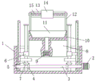
Fig. 1 is the structural schematic diagram of the utility model discloses an intelligent camera revolving stage mechanism that proposes.
Fig. 2 is a front view of the present invention, which provides an intelligent camera turntable mechanism.
Reference numbers in the figures: the device comprises a base 1, a motor 2, a rotating rod 3, a first bevel gear 4, a threaded rod 5, a threaded sleeve 6, a second bevel gear 7, a lifting block 8, a driving motor 9, a supporting disk 10, a rotating disk 11, a supporting rod 12, a fixing plate 13, a double-shaft motor 14, a rotating shaft 15, a camera 16, a camera 17 and an infrared sensor 18.
Detailed Description
The technical solutions in the embodiments of the present invention will be described clearly and completely with reference to the accompanying drawings in the embodiments of the present invention, and it is obvious that the described embodiments are only some embodiments of the present invention, not all embodiments.
Referring to fig. 1-2, an intelligent camera turntable mechanism comprises a base 1, a motor 2 is fixedly installed on the right wall of the base 1, an output end of the motor 2 is fixedly connected with a rotating rod 3, the other end of the rotating rod 3 is rotatably connected with the left inner wall of the base 1, two threaded rods 5 and two supporting plates are rotatably installed on the inner bottom wall of the base 1, threaded sleeves 6 are threadedly installed on the threaded rods 5, sliding grooves are formed in the side walls of the supporting plates, sliding seats are slidably installed in the sliding grooves, the two sliding seats are fixedly connected with corresponding threaded sleeves 6, the same lifting block 8 is fixedly connected with the two threaded sleeves 6, a driving motor 9 is embedded in the lifting block 8, a supporting plate 10 is fixedly connected with the top surface of the lifting block 8, a rotating plate 11 is rotatably installed in the supporting plate 10, the output end of the driving motor, the both ends fixedly connected with bracing piece 12 of rolling disc 11 top surface, the same fixed plate 13 of fixedly connected with between two bracing pieces 12, fixed plate 13 fixed mounting has double-shaft motor 14, the equal fixedly connected with pivot 15 of output of double-shaft motor 14, two pivot 15 cover changees have same camera 16, fixed mounting has 7 camera 17 and infrared sensor 18 on the camera 16, the left side of base 1, right inner wall fixed mounting has the bearing frame, the threaded rod rotates and runs through the bearing frame, the external diameter of threaded rod 5 is less than the internal diameter of thread bush 6, the external screw thread of threaded rod 5 and the internal thread adaptation of thread bush 6, the size adaptation of spout and slide, the internal diameter of supporting disk 10 and the external diameter size adaptation of rolling disc 11, double-shaft motor 14 is the.
The working principle is as follows: the utility model discloses, when using, when infrared ray sensor 18 experiences the removal of object, motor 2 will be opened, motor 2's output drives dwang 3 and rotates, through first bevel gear 4 and the meshing of second bevel gear 7, it rotates to drive threaded rod 5, under the cooperation of spout and slide, it rises to drive thread bush 6, thereby it rises to drive elevator 8, when the rotation is controlled to needs, driving motor 9 is opened to the control box, driving motor 9's output drives rolling disc 11 and rotates, when needs carry out the fore-and-aft rotation, open biax motor 14, the output of biax motor 14 drives pivot 15 and rotates, thereby it rotates around driving camera 16, thereby follow the removal of object.
In the description of the present invention, it is to be understood that the terms "center", "longitudinal", "lateral", "length", "width", "thickness", "upper", "lower", "front", "rear", "left", "right", "vertical", "horizontal", "top", "bottom", "inner", "outer", "clockwise", "counterclockwise", and the like indicate orientations or positional relationships based on the orientations or positional relationships shown in the drawings, and are only for convenience of description and to simplify the description, but do not indicate or imply that the device or element referred to must have a particular orientation, be constructed and operated in a particular orientation, and therefore should not be construed as limiting the present invention.
Furthermore, the terms "first", "second" and "first" are used for descriptive purposes only and are not to be construed as indicating or implying relative importance or implicitly indicating the number of technical features indicated. Thus, a feature defined as "first" or "second" may explicitly or implicitly include one or more of that feature. In the description of the present invention, "a plurality" means two or more unless specifically limited otherwise.
The above, only be the concrete implementation of the preferred embodiment of the present invention, but the protection scope of the present invention is not limited thereto, and any person skilled in the art is in the technical scope of the present invention, according to the technical solution of the present invention and the utility model, the concept of which is equivalent to replace or change, should be covered within the protection scope of the present invention.
Claims (6)
1. The utility model provides an intelligent camera revolving stage mechanism, includes base (1), its characterized in that, the right wall fixed mounting of base (1) has motor (2), the output fixedly connected with dwang (3) of motor (2), the other end of dwang (3) and the left inner wall of base (1) rotate to be connected, the inner diapire of base (1) rotates and installs two threaded rods (5) and two backup pads, threaded sleeve (6) are installed to the screw thread on threaded rod (5), the lateral wall of backup pad is equipped with the spout, slidable mounting has the slide in the spout, two slide and corresponding threaded sleeve (6) fixed connection, two same elevator (8) of threaded sleeve (6) fixed connection, embedded driving motor (9) that is equipped with in elevator (8), the top surface fixedly connected with supporting disk (10) of elevator (8), rolling disc (11) are installed to supporting disk (10) internal rotation, the output of driving motor (9) is rotated and is hung and run through elevator (8) and supporting disk (10) and rolling disc (11) fixed connection, both ends fixedly connected with bracing piece (12), two of rolling disc (11) top surface fixedly connected with is same fixed plate (13) between bracing piece (12), fixed plate (13) fixed mounting has biax motor (14), the equal fixedly connected with pivot (15) of output of biax motor (14), two pivot (15) cover is changeed there is same camera (16), fixed mounting has 7 camera (17) and infrared ray sensor (18) on camera (16).
2. An intelligent camera turntable mechanism according to claim 1, characterized in that bearing seats are fixedly mounted on the left and right inner walls of the base (1), and the threaded rod is rotatably inserted through the bearing seats.
3. A smart camera turret mechanism according to claim 1, characterized in that the outer diameter of the threaded rod (5) is smaller than the inner diameter of the threaded sleeve (6), the outer thread of the threaded rod (5) fitting the inner thread of the threaded sleeve (6).
4. An intelligent camera turret mechanism according to claim 1, wherein the sliding channel and the sliding base are sized to fit together.
5. A smart camera turret mechanism according to claim 1, characterized in that the inner diameter of the support disc (10) is adapted to the outer diameter of the rotating disc (11).
6. A smart camera turret mechanism according to claim 1, characterized in that said two-axis motor (14) is a counter-rotating motor.
Priority Applications (1)
| Application Number | Priority Date | Filing Date | Title |
|---|---|---|---|
| CN202021082402.8U CN212617358U (en) | 2020-06-12 | 2020-06-12 | Intelligent camera turntable mechanism |
Applications Claiming Priority (1)
| Application Number | Priority Date | Filing Date | Title |
|---|---|---|---|
| CN202021082402.8U CN212617358U (en) | 2020-06-12 | 2020-06-12 | Intelligent camera turntable mechanism |
Publications (1)
| Publication Number | Publication Date |
|---|---|
| CN212617358U true CN212617358U (en) | 2021-02-26 |
Family
ID=74717113
Family Applications (1)
| Application Number | Title | Priority Date | Filing Date |
|---|---|---|---|
| CN202021082402.8U Active CN212617358U (en) | 2020-06-12 | 2020-06-12 | Intelligent camera turntable mechanism |
Country Status (1)
| Country | Link |
|---|---|
| CN (1) | CN212617358U (en) |
Cited By (2)
| Publication number | Priority date | Publication date | Assignee | Title |
|---|---|---|---|---|
| CN113206898A (en) * | 2021-03-26 | 2021-08-03 | 闻泰通讯股份有限公司 | Control method and control system of lifting device and terminal equipment |
| CN114087510A (en) * | 2021-10-29 | 2022-02-25 | 深圳市华安泰智能科技有限公司 | Article model identification device and method based on binocular vision |
-
2020
- 2020-06-12 CN CN202021082402.8U patent/CN212617358U/en active Active
Cited By (2)
| Publication number | Priority date | Publication date | Assignee | Title |
|---|---|---|---|---|
| CN113206898A (en) * | 2021-03-26 | 2021-08-03 | 闻泰通讯股份有限公司 | Control method and control system of lifting device and terminal equipment |
| CN114087510A (en) * | 2021-10-29 | 2022-02-25 | 深圳市华安泰智能科技有限公司 | Article model identification device and method based on binocular vision |
Similar Documents
| Publication | Publication Date | Title |
|---|---|---|
| CN114034720B (en) | Protective glass defect detection equipment | |
| CN211600055U (en) | Image acquisition device based on binocular camera | |
| CN212900811U (en) | Large-aperture glass-plastic mixed high-low temperature confocal optical device | |
| CN205722619U (en) | A kind of rotary-type electron album | |
| CN213948803U (en) | Multi-angle aerial survey device | |
| CN207065021U (en) | Hand-held head | |
| CN212696086U (en) | Vehicle-mounted rotatable camera | |
| CN209803664U (en) | Intelligent display terminal | |
| CN114360092A (en) | A patrol and examine security protection equipment for data center computer lab | |
| CN113803596A (en) | A video work display device for practical teaching | |
| CN210510791U (en) | Automatic acquisition device for visual data set | |
| CN216719191U (en) | Touch screen type ordering machine | |
| CN217912095U (en) | Digital twin visualization device | |
| CN111503477B (en) | Illegal ship tracking system and method | |
| CN213935458U (en) | Display device capable of folding and unfolding mobile phone support | |
| CN211423832U (en) | Novel multimedia display platform for scientific and technological management information release | |
| CN212541160U (en) | Big data display device | |
| CN213938054U (en) | Collection system mounting structure for image processing | |
| CN210691410U (en) | Face identification equipment subassembly of punching card | |
| CN114141128A (en) | Data analysis display device for accounting | |
| CN216565307U (en) | Recording and developing equipment for first-class online open video courses | |
| CN207843399U (en) | Roll film device | |
| CN106488096A (en) | Camera head for monitoring anti-theft system | |
| CN219655703U (en) | Recognition device for remote sensing image change monitoring | |
| CN219179982U (en) | An access control security card reader |
Legal Events
| Date | Code | Title | Description |
|---|---|---|---|
| GR01 | Patent grant | ||
| GR01 | Patent grant |