CN212599188U - Double-rotation center frame screw milling machine - Google Patents
Double-rotation center frame screw milling machine Download PDFInfo
- Publication number
- CN212599188U CN212599188U CN202021158602.7U CN202021158602U CN212599188U CN 212599188 U CN212599188 U CN 212599188U CN 202021158602 U CN202021158602 U CN 202021158602U CN 212599188 U CN212599188 U CN 212599188U
- Authority
- CN
- China
- Prior art keywords
- milling
- head
- bed
- chuck
- worm wheel
- Prior art date
- Legal status (The legal status is an assumption and is not a legal conclusion. Google has not performed a legal analysis and makes no representation as to the accuracy of the status listed.)
- Active
Links
- 238000003801 milling Methods 0.000 title claims abstract description 131
- 230000005540 biological transmission Effects 0.000 claims description 5
- 230000009977 dual effect Effects 0.000 claims 4
- 230000033001 locomotion Effects 0.000 abstract description 21
- 230000000694 effects Effects 0.000 abstract description 4
- 210000000078 claw Anatomy 0.000 description 6
- 238000003754 machining Methods 0.000 description 3
- 238000005516 engineering process Methods 0.000 description 2
- 235000019504 cigarettes Nutrition 0.000 description 1
- 239000002184 metal Substances 0.000 description 1
- 238000000034 method Methods 0.000 description 1
- 239000007787 solid Substances 0.000 description 1
Images

Landscapes
- Machine Tool Units (AREA)
Abstract
The utility model relates to a double-rotation center frame screw milling machine, a left center frame body and a right center frame body are symmetrically and fixedly arranged on a machine body of the milling machine, an X-direction guide rail is fixed on the machine body, a milling head is slidably connected on the X-direction guide rail, a milling head body bearing is connected with a milling head core, the milling head core is also clamped with a first rotating device, and a milling cutter is connected with a bottom bearing of the milling head core; a Z-direction guide rail is fixed on the bed body, a bed head is connected onto the Z-direction guide rail in a sliding mode, and a second rotating device is further clamped on the bed head spindle. The utility model discloses a press from both sides tight body and clamping jaw can carry out the rotary motion coaxial with the work piece through the hollow shaft, guaranteed support rigidity and support accuracy, realize improving the screw rod from this and mill the good effect of precision and milling efficiency.
Description
Technical Field
The utility model relates to a metal cutting processing technology field, concretely relates to double helix centre frame screw rod milling machine.
Background
The current industrial development is changing day by day, the demand for spiral curved surface parts represented by screw pumps and screw motor rotors is increasing, and the requirements for the processing precision and the processing efficiency of products are higher and higher.
The screw milling machine is a special milling machine tool, and the spiral groove of the slender screw rotor is milled on the screw milling machine. However, the workpiece centering center frame used on the existing machine tool cannot meet the increasingly improved requirements of the screw machining precision from the working principle to the aspects of the mechanical structure and the like, and the screw milling machine has poor rigidity, poor screw machining precision, unstable quality and poor consistency of spiral grooves.
Disclosure of Invention
Utility model purpose: the utility model provides a two rotatory centre frame screw rod milling machines, its purpose is solved current screw rod milling machine rigidity poor and the poor problem of screw rod machining precision.
The technical scheme is as follows:
a double-rotation center frame screw milling machine is characterized in that a left center frame body and a right center frame body are symmetrically and fixedly arranged on a machine body of the milling machine, a left chuck is axially connected to the left center frame body, and a right chuck is axially connected to the right center frame body;
an X-direction guide rail is fixed on the lathe bed, a milling head is connected to the X-direction guide rail in a sliding manner, an X-direction driving motor is fixedly arranged on the lathe bed and is connected with a milling head body of the milling head, a milling head core is connected to a bearing of the milling head body, and a milling cutter is connected to a bottom end bearing of the milling head core; the milling head core is also clamped with a first rotating device, and a rotating motor is fixedly arranged on the milling head core and is in transmission connection with the milling cutter;
a Z-direction guide rail is fixed on the bed body, and a bed head is connected on the Z-direction guide rail in a sliding manner; a Z-direction driving motor is fixed at the end part of the bed body and is connected with a bed head body of the bed head, a bed head body bearing is connected with a bed head main shaft, a bed head chuck is fixedly connected at the end part of the bed head main shaft, and the bed head body is connected with a Z-direction guide rail in a sliding manner; the bed head main shaft is also clamped with a second rotating device.
The clamping force of the left chuck is consistent with that of the right chuck, and the clamping force of the head chuck is larger than that of the left chuck or the right chuck.
The left chuck and the right chuck are both wedge type chucks.
The first rotating device comprises a first worm wheel and a first worm wheel rod, the milling head core is clamped in the first worm wheel, the periphery of the first worm wheel is meshed with the first worm wheel rod, one end of the first worm wheel rod is connected with a driving device, and the driving device is fixed on the milling head body.
The second rotating device comprises a second worm wheel and a second worm wheel rod, the spindle of the bed head is clamped with the inner periphery of the second worm wheel, the periphery of the second worm wheel is meshed with the second worm wheel rod, one end of the second worm wheel rod is connected with a driving device, and the driving device is fixed.
The advantages and effects are as follows:
1. the clamping body and the clamping claws of the double-rotation center frame can rotate coaxially with the workpiece through the hollow shaft, so that the supporting rigidity and the supporting precision are ensured, and the good effects of improving the milling precision and the milling efficiency of the screw are realized.
2. The utility model provides a two rotatory center framves compare with original screw rod milling machine's two fixed center framves, the effectual work drawbacks such as chip removal difficulty of having avoided two fixed center framves structure to exist.
The utility model discloses showing and improving screw rod processing technology level, quality level and economic benefits. The milling machine is mainly applied to milling of single-head and multi-head screw rotors, stator mandrels and other workpieces of single-screw pumps and single-screw motors.
Description of the drawings:
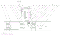
fig. 1 is a schematic structural view of the present invention;
FIG. 2 is a schematic view of the internal structure of the present invention;
in the figure: 1. the milling machine comprises a left center frame body, a 2 left chuck, a 3 left clamping jaw, a 4 milling head body, a 5X-direction guide rail, a 6 milling cutter, a 7 right clamping jaw, a 8 right chuck, a 9 right center frame body, a 10 headstock spindle, a 11 lathe bed, a 12 workpiece, a 13 lathe head body, a 14Z-direction guide rail, a 15 milling head, a 16 milling head core, a 17 first worm gear, an 18 rotating motor, a 19 first worm gear rod, a 20 cutter head shaft, a 21Z-direction driving motor, a 22Z-direction screw rod, a 23 second worm gear, a 24 second worm gear rod, a 25 lathe head chuck, a 26X-direction driving motor, a 27X-direction screw rod, a 28 lathe head, a 29 left clamping body and a 30 right clamping body.
The specific implementation mode is as follows:
the utility model provides a two rotation center frame screw rod milling machines, for improving the rigidity that mills the process systems, the utility model discloses install two "work piece centering center framves" in milling cutter left and right sides (or refer to the front and back) both sides, form two rotation center frame, it is centre gripping work piece around the cutter mills the position. The milling cutter comprises a milling cutter body, a milling cutter head, a clamping body, a clamping jaw, a clamping body and a clamping jaw, wherein the milling cutter head is arranged on the milling cutter head, the clamping body is arranged on the milling cutter head, the milling cutter head is arranged on the milling cutter head, the clamping jaw is arranged on the milling cutter head, the milling cutter. When the milling machine works, a workpiece penetrates through the hollow shaft of the center frame, the clamping claws of the center frame are contacted with and clamp the workpiece, and the rotating motion of the workpiece in the milling process drives the clamping claws and the clamping body to rotate, namely the workpiece and the clamping claws do not rotate relatively; the axial movement of the workpiece in the milling process cannot drive the clamping jaw to do axial movement, namely, the workpiece and the clamping jaw have axial relative sliding movement.
A double-rotation center frame screw milling machine is characterized in that a machine body 11 of the milling machine is symmetrically and fixedly provided with a left center frame body 1 and a right center frame body 9 in the horizontal direction, a left chuck 2 is axially connected to the left center frame body 1, and a right chuck 8 is axially connected to the right center frame body 9; the left chuck 2 and the right chuck 8 can rotate coaxially with the workpiece through the hollow shaft, so that the supporting rigidity and the supporting precision are guaranteed, good effects of improving the milling precision and the milling efficiency of the screw are achieved, and meanwhile the problem of difficult chip removal is avoided. An X-direction guide rail 5 is fixed in the vertical direction of the lathe bed 11, the X-direction guide rail 5 is arranged between the left center frame body 1 and the right center frame body 9, a milling head 15 is connected onto the X-direction guide rail 5 in a sliding manner, and the milling head 15 realizes the feeding rotation of the milling cutter 6 in the vertical direction of the lathe bed 11; an X-direction driving motor 26 is fixedly arranged on the lathe bed 11, an X-direction screw 27 of the X-direction driving motor 26 is in threaded connection with a milling head body 4 of the milling head 15, the milling head body 4 is in sliding connection with an X-direction guide rail 5, a milling head core 16 is in bearing connection with the milling head body 4, and a milling cutter 6 is in bearing connection with the bottom end of the milling head core 16.
The X-direction driving motor 26 drives the X-direction screw rod 27 to rotate, and the milling head body 4 screwed with the X-direction screw rod 27 can be driven to slide up and down along the X-direction guide rail 5, so as to drive the milling cutter 6 to slide up and down along the X-direction guide rail 5, that is, to move up and down in the X direction.
The milling head core 16 is further clamped with a first rotating device, the first rotating device can be of a worm gear structure or a rotating motor, the worm gear structure is preferred in the application, the first rotating device comprises a first worm gear 17 and a first worm gear rod 19, specifically, the milling head core 16 is clamped with the inside of the first worm gear 17, the periphery of the first worm gear 17 is meshed with the first worm gear rod 19, one end of the first worm gear rod 19 is connected with a driving device, the driving device is fixed on the milling head body 4, the first worm gear rod 19 is in bearing connection with the milling head body 4 and further drives the first worm gear 17 to rotate, the first worm gear 17 rotates to drive the milling head core 16 to rotate, the milling head core 16 rotates to realize rotation of the milling cutter 6, so that an included angle between the axis of the milling cutter 6 and the axis of the workpiece 12 is formed, and the workpiece 12 forms spiral grooves with different shapes when the.
The first worm gear 19 is driven to move to drive the first worm gear 17 to rotate on the axis A, and the first worm gear 17 rotates to drive the milling head core 16 to rotate on the axis A, namely, the milling cutter 6 connected to the bottom end of the milling head core 16 can rotate on the axis A. Thus, the feeding and rotating device in the vertical direction can drive the milling cutter 6 to move up and down in the X direction for feeding, and can also drive the milling cutter 6 to rotate along the A axis.
The upper end of the milling head core 16 is also fixedly provided with a rotating motor 18, and the rotating motor 18 is in transmission connection with a cutter head shaft 20 of the milling cutter 6 through a transmission belt; namely, the rotation of the rotating motor 18 can drive the cutter head shaft 20 to rotate through the transmission belt, so as to realize the rotation of the milling cutter 6, and the milling cutter 6 can perform the processing of milling the spiral groove on the workpiece 12. As described above, the milling cutter 6 can be fed vertically in the X direction, can be rotated about the a axis, and can also be rotated in the circumferential direction.
A Z-direction guide rail 14 is fixed on the bed body 11 in the horizontal direction, and a bed head 28 is connected on the Z-direction guide rail 14 in a sliding manner; the bed head 28 performs feed rotation of the workpiece 12 on the bed 11. A Z-direction driving motor 21 is fixed at the end part of the bed body 11 in the horizontal direction, a Z-direction screw rod 22 of the Z-direction driving motor 21 is in threaded connection with a bed head body 13 of a bed head 28, the bed head body 13 is in bearing connection with a bed head main shaft 10, a bed head chuck 25 is fixedly connected at the end part of the bed head main shaft 10, and the bed head body 13 is in sliding connection with a Z-direction guide rail 14. The X-direction guide rail 5 and the Z-direction guide rail 14 are conventional linear guide rails.
Drive Z through Z to driving motor 21 and rotate to lead screw 22, can drive the head of a bed body 13 with Z to lead screw 22 threaded connection and slide along Z to guide rail 14 left and right and feed, the head of a bed body 13 drives head of a bed main shaft 10 and slides along Z to guide rail 14 left and right and feed, head of a bed main shaft 10 tip fixedly connected with head of a bed chuck 25, head of a bed chuck 25 is used for joint work piece 12, thereby Z can drive work piece 12 to slide along Z to guide rail 14 and feed to Z, remove about Z upwards promptly.
The bed head main shaft 10 is further clamped with a second rotating device, the second rotating device can be of a worm gear structure and can also be used for rotating a motor, the worm gear structure is preferred in the application, the second rotating device comprises a second worm wheel 23 and a second worm wheel rod 24, the bed head main shaft 10 is clamped with the inner periphery of the second worm wheel 23, the periphery of the second worm wheel 23 is meshed with the second worm wheel rod 24, one end of the second worm wheel rod 24 is connected with a driving device, the driving device is fixed on the bed head body 13, the other end of the second worm wheel rod 24 is connected with a bearing of the bed head body 13, and the workpiece 12 is rotated and fed.
The second worm gear rod 24 is driven to move to drive the second worm gear 23 to rotate around the axis C, and the second worm gear 23 rotates to drive the headstock spindle 10 to rotate around the axis C, that is, the headstock spindle 10 drives the workpiece 12 to rotate around the axis C. Thus, the feeding rotating device in the horizontal direction can drive the workpiece 12 to move left and right in the Z direction for feeding, and can also drive the workpiece 12 to rotate along the C axis.
The clamping force of the left chuck 2 and the right chuck 8 is the same, and the clamping force of the head chuck 25 is larger than that of the left chuck 2 or the right chuck 8. The left chuck 2, the right chuck 8 and the headstock chuck 25 are all existing products and are all connected with pneumatic or hydraulic devices to provide power for chuck clamping. The left chuck 2 and the right chuck 8 are commercially available from cigarette pack Rongjiang machine tool Accessory, Inc., model number KZW 53D.
The headstock chuck 25 is a conventional solid chuck, and when the headstock chuck 25 holds the workpiece 12, the headstock chuck 25 is capable of driving the workpiece 12 to rotate circumferentially and to feed axially, which is equivalent to a rigid connection. Since the clamping force of the headstock chuck 25 is greater than the clamping force of either the left chuck 2 or the right chuck 8, the workpiece 12 can move axially within the left chuck 2 and the right chuck 8 as the headstock chuck 25 moves the workpiece 12 axially.
The left chuck 2 and the right chuck 8 are both wedge pneumatic or hydraulic existing chucks.
The left clamping body 29 of the left chuck 2 is fixedly provided with a left clamping claw 3, and the right clamping body 30 of the right chuck 8 is fixedly provided with a right clamping claw 7.
When the workpiece milling device works, the left clamping jaw 3 and the right clamping jaw 7 can perform radial clamping and loosening motion of a workpiece under hydraulic or pneumatic driving, the left clamping jaw 3 and the right clamping jaw 7 are used for clamping the workpiece 12, and the left clamping jaw 3 and the right clamping jaw 7 are driven to synchronously rotate under the action of rotary motion of the workpiece 12 in the milling process, because the left clamping jaw 3 is fixedly clamped with the left clamping body 29, the right clamping jaw 7 is fixedly clamped with the right clamping body 30, the left clamping body 29 is in bearing connection with the left center frame body 1, and the right clamping body 30 is in bearing connection with the right center frame body 9, the rotary motion of the workpiece 12 in the milling process drives the left clamping body 29 and the right clamping body 30 to synchronously rotate through the left clamping jaw 3 and the right clamping jaw 7; the wedge chuck has a small contact area with the workpiece 12, i.e., only contacts the workpiece 12 through the left and right clamping jaws 3 and 7. Providing a radial clamping force on the workpiece 12, but the axial friction force of the workpiece 12 is small, the workpiece 12 penetrates through the hollow shafts of the left center frame body 1 and the right center frame body 9, the left clamping jaw 3 and the right clamping jaw 7 are in contact with and clamp the workpiece 12, and the rotary motion of the workpiece 12 in the milling process drives the clamping jaws and the clamping bodies (the left chuck 2 and the right chuck 8) to rotate, namely, the workpiece 12 and the left clamping jaw 3 and the right clamping jaw 7 do not rotate relatively; the axial movement of the workpiece 12 in the milling process cannot drive the left clamping jaw 3 and the right clamping jaw 7 to axially move, that is, the workpiece 12 and the left clamping jaw 3 and the right clamping jaw 7 axially slide relatively.
The working mode is as follows:
the workpiece 12 penetrates through the left clamping body 2 of the left center frame body 1 and the right clamping body 8 of the right center frame body 9, the left clamping body 2 and the right clamping body 8 are in contact with the workpiece 12 and clamp the workpiece 12 through the left clamping jaw 3 and the right clamping jaw 7, the headstock 28 drives the rotary feed motion of the workpiece 12 (the milling motion of the workpiece 12), specifically, the headstock chuck 25 clamps the workpiece 12 and drives the workpiece 12 to rotate circumferentially through the second worm gear rod 24, namely, the workpiece 12 rotates around the axis C; the Z-direction drive motor 21 drives the workpiece 12 to slide along the Z-direction guide rail 14. The rotating motion in the milling process of the workpiece 12 drives the left clamping body 2 and the right clamping body 8 to synchronously rotate; the axial movement of the workpiece 12 in the milling process, i.e. the feed movement, cannot drive the left clamping jaw 3 and the right clamping jaw 7 to make axial movement, i.e. there is axial relative sliding movement between the workpiece 12 and the left clamping jaw 3 and the right clamping jaw 7.
According to the requirement of milling the spiral groove, the angle of the milling cutter 6 is adjusted through the first rotating device, namely the milling cutter 6 rotates by an A axis to adjust the angle; the X-direction drive motor 26 drives the milling head 15 to slide and feed along the X-direction guide 5, thereby driving the milling cutter 6 to slide and feed along the X-direction guide 5. The rotating motor 18 drives the cutter head shaft 20 to rotate through the conveyor belt, and further the milling cutter 6 rotates and mills the workpiece 12.
In the structure, the unit consisting of the left center frame body 1, the right center frame body 9, the milling head body 4 and the X-direction guide rail 5 can be fixed at one end of the lathe bed 11, and the lathe head 28 of the lathe bed drives the workpiece 12 to perform Z-direction feeding motion and rotation motion along the C axis, so that the axial relative motion of the milling cutter 6 and the workpiece 12 is completed; the unit consisting of the left center frame body 1, the right center frame body 9, the milling head body 4 and the X-direction guide rail 5 can also be mounted on the lathe bed 11 through the Z-direction guide rail 10, so that the unit can move in the Z direction, and other parts of the lathe bed drive the workpiece 12 to rotate along the C axis, so as to complete the axial relative movement of the milling cutter 6 and the workpiece 12.
The utility model discloses a two rotatory center frame screw rod milling machines are on the basis of deep analysis and the two fixed center frame theory of operation of the current screw rod milling machine of research and mechanical structure work drawback, change center frame's theory of operation, support mode and mechanical structure and utility model discloses a novel screw rod milling machine, it has improved the support rigidity and the support precision of work piece to reach the purpose that improves the screw rod and mill precision and mill efficiency.
Claims (5)
1. The utility model provides a two rotatory centre frame screw rod milling machines which characterized in that: a left central frame body (1) and a right central frame body (9) are symmetrically and fixedly arranged on a lathe bed (11) of the milling machine, a left chuck (2) is axially connected with the left central frame body (1), and a right chuck (8) is axially connected with the right central frame body (9);
an X-direction guide rail (5) is fixed on a lathe bed (11), a milling head (15) is connected onto the X-direction guide rail (5) in a sliding manner, an X-direction driving motor (26) is fixedly arranged on the lathe bed (11), the X-direction driving motor (26) is connected with a milling head body (4) of the milling head (15), a milling head core (16) is connected to a bearing of the milling head body (4), and a milling cutter (6) is connected to a bearing of the bottom end of the milling head core (16); the milling head core (16) is also clamped with a first rotating device, the milling head core (16) is also fixedly provided with a rotating motor (18), and the rotating motor (18) is in transmission connection with the milling cutter (6);
a Z-direction guide rail (14) is fixed on the bed body (11), and a bed head (28) is connected on the Z-direction guide rail (14) in a sliding way; a Z-direction driving motor (21) is fixed at the end part of the bed body (11), the Z-direction driving motor (21) is connected with a bed head body (13) of a bed head (28), the bed head body (13) is connected with a bed head main shaft (10) through a bearing, a bed head chuck (25) is fixedly connected at the end part of the bed head main shaft (10), and the bed head body (13) is in sliding connection with a Z-direction guide rail (14); the spindle (10) of the bed head is also clamped with a second rotating device.
2. The dual rotation center frame screw milling machine of claim 1, wherein: the clamping force of the left chuck (2) is consistent with that of the right chuck (8), and the clamping force of the head chuck (25) is greater than that of the left chuck (2) or the right chuck (8).
3. The dual rotation center frame screw milling machine of claim 1, wherein: the left chuck (2) and the right chuck (8) are both wedge type chucks.
4. The dual rotation center frame screw milling machine of claim 1, wherein: the first rotating device comprises a first worm wheel (17) and a first worm wheel rod (19), a milling head core (16) is clamped in the first worm wheel (17), the periphery of the first worm wheel (17) is meshed with the first worm wheel rod (19), one end of the first worm wheel rod (19) is connected with a driving device, and the driving device is fixed on the milling head body (4).
5. The dual rotation center frame screw milling machine of claim 1, wherein: the second rotating device comprises a second worm wheel (23) and a second worm wheel rod (24), the spindle (10) of the bed head is clamped with the inner periphery of the second worm wheel (23), the periphery of the second worm wheel (23) is meshed with the second worm wheel rod (24), one end of the second worm wheel rod (24) is connected with a driving device, and the driving device is fixed on the bed head body (13).
Priority Applications (1)
| Application Number | Priority Date | Filing Date | Title |
|---|---|---|---|
| CN202021158602.7U CN212599188U (en) | 2020-06-22 | 2020-06-22 | Double-rotation center frame screw milling machine |
Applications Claiming Priority (1)
| Application Number | Priority Date | Filing Date | Title |
|---|---|---|---|
| CN202021158602.7U CN212599188U (en) | 2020-06-22 | 2020-06-22 | Double-rotation center frame screw milling machine |
Publications (1)
| Publication Number | Publication Date |
|---|---|
| CN212599188U true CN212599188U (en) | 2021-02-26 |
Family
ID=74756166
Family Applications (1)
| Application Number | Title | Priority Date | Filing Date |
|---|---|---|---|
| CN202021158602.7U Active CN212599188U (en) | 2020-06-22 | 2020-06-22 | Double-rotation center frame screw milling machine |
Country Status (1)
| Country | Link |
|---|---|
| CN (1) | CN212599188U (en) |
Cited By (3)
| Publication number | Priority date | Publication date | Assignee | Title |
|---|---|---|---|---|
| CN112958857A (en) * | 2021-04-08 | 2021-06-15 | 嘉兴市旺益机械有限公司 | Multi-angle efficient milling device for screw |
| CN113523389A (en) * | 2021-08-13 | 2021-10-22 | 百事德机械(江苏)有限公司 | Planing device for screw fan rotor and using method thereof |
| CN119159174A (en) * | 2024-10-24 | 2024-12-20 | 江苏利润友机械科技有限公司 | A screw processing rotary milling equipment |
-
2020
- 2020-06-22 CN CN202021158602.7U patent/CN212599188U/en active Active
Cited By (4)
| Publication number | Priority date | Publication date | Assignee | Title |
|---|---|---|---|---|
| CN112958857A (en) * | 2021-04-08 | 2021-06-15 | 嘉兴市旺益机械有限公司 | Multi-angle efficient milling device for screw |
| CN113523389A (en) * | 2021-08-13 | 2021-10-22 | 百事德机械(江苏)有限公司 | Planing device for screw fan rotor and using method thereof |
| CN119159174A (en) * | 2024-10-24 | 2024-12-20 | 江苏利润友机械科技有限公司 | A screw processing rotary milling equipment |
| CN119159174B (en) * | 2024-10-24 | 2025-03-04 | 江苏利润友机械科技有限公司 | Screw rod processing rotary milling equipment |
Similar Documents
| Publication | Publication Date | Title |
|---|---|---|
| CN110508832B (en) | Multi-cutter efficient synchronous dynamic balance turning machine tool and machining method | |
| CN101961836B (en) | Numerically-controlled gantry type vertical and horizontal combined machine tool | |
| CN103350343B (en) | The numerical control gantry vertical that a kind of tool magazine and main shaft are compounded in saddle crouches Compositions of metal-working machines | |
| CN111843492B (en) | Single-cylinder two-stroke engine cylinder sleeve processing equipment and using method thereof | |
| CN106424867B (en) | A New Vertical Milling Machine Based on Cycloid Rotation | |
| CN203343729U (en) | Numerically-controlled gantry vertical-and-horizontal compound machining center with tool magazines and main shafts compounded on saddles | |
| CN102366889A (en) | Automatic high-speed precision numerical control machine tool for cutting spherical surface | |
| CN110102837B (en) | Numerical control nine-axis secondary enveloping worm multifunctional whirling milling machine tool | |
| CN101134248A (en) | Three-head helix milling machine | |
| CN116494029A (en) | Multi-station Tool Machining Center | |
| CN210451762U (en) | Turning and milling combined machine tool | |
| CN201220277Y (en) | Precise numerical control lathe | |
| CN201102097Y (en) | Three-head helix milling machine | |
| CN103273145A (en) | Method for machining worm shaft sleeve spiral teeth of revolving cup spinning machine | |
| CN110449903A (en) | Complex milling machine tool | |
| CN214518752U (en) | Turn-milling machine with automatic blanking mechanism | |
| CN118926554A (en) | Machine tools for turning the inner surface of workpieces with large aspect ratio | |
| CN208341858U (en) | A kind of Production of bearing cutting equipment | |
| CN218252914U (en) | Full-automatic double-shaft numerical control lathe | |
| CN207058133U (en) | A kind of processing unit (plant) of the deficient groove of workpiece spindle | |
| CN113290280B (en) | A high-efficient processingequipment for major axis gear hobbing processing | |
| CN213196472U (en) | Horizontal compound grinding machine | |
| CN214237070U (en) | Pipe fitting machining device | |
| CN204639273U (en) | Helicoid hydraulic motor rotor helical-screw groove broach-milling device | |
| CN102756155B (en) | Numerical control fixed workpiece excircle processing device |
Legal Events
| Date | Code | Title | Description |
|---|---|---|---|
| GR01 | Patent grant | ||
| GR01 | Patent grant |