CN212598648U - Well head pressure truck valves forges and presses seat for oil development - Google Patents
Well head pressure truck valves forges and presses seat for oil development Download PDFInfo
- Publication number
- CN212598648U CN212598648U CN202021225927.2U CN202021225927U CN212598648U CN 212598648 U CN212598648 U CN 212598648U CN 202021225927 U CN202021225927 U CN 202021225927U CN 212598648 U CN212598648 U CN 212598648U
- Authority
- CN
- China
- Prior art keywords
- die
- forging
- valve body
- cavity
- lower die
- Prior art date
- Legal status (The legal status is an assumption and is not a legal conclusion. Google has not performed a legal analysis and makes no representation as to the accuracy of the status listed.)
- Active
Links
- 238000011161 development Methods 0.000 title claims abstract description 12
- 238000005242 forging Methods 0.000 claims abstract description 53
- 230000003137 locomotive effect Effects 0.000 claims abstract description 3
- 238000004080 punching Methods 0.000 claims 2
- 238000004519 manufacturing process Methods 0.000 abstract description 6
- 239000000463 material Substances 0.000 abstract description 4
- 238000001125 extrusion Methods 0.000 abstract description 2
- 238000003825 pressing Methods 0.000 description 15
- 238000000034 method Methods 0.000 description 3
- 230000000694 effects Effects 0.000 description 2
- 238000003754 machining Methods 0.000 description 2
- 238000003672 processing method Methods 0.000 description 2
- 238000013461 design Methods 0.000 description 1
- 238000010586 diagram Methods 0.000 description 1
- 238000006073 displacement reaction Methods 0.000 description 1
- 230000001788 irregular Effects 0.000 description 1
- 239000002184 metal Substances 0.000 description 1
- 238000012986 modification Methods 0.000 description 1
- 230000004048 modification Effects 0.000 description 1
- 239000003208 petroleum Substances 0.000 description 1
- 239000002994 raw material Substances 0.000 description 1
Images
Landscapes
- Forging (AREA)
Abstract
The utility model provides a well head pressure locomotive valves forges and presses seat for oil development for solve current valve body mould structure complicacy, work efficiency low, manufacturing cost high, use inconvenient scheduling problem. The utility model comprises a die holder, wherein a lower die is arranged on the die holder, the lower die is connected with an upper die, a forging platform is movably arranged in the lower die, and die cavity structures matched with a valve body are arranged on the lower die, the upper die and the forging platform; and a base plate is arranged between the lower die and the die holder, and an ejector rod for pushing the forging platform to move is arranged at the lower part of the die holder. The utility model discloses simple structure, work efficiency is high, can demold smoothly after the valve body extrusion, and the mechanical properties of fashioned valve body is high, saves raw and other materials, reduce cost.
Description
Technical Field
The utility model relates to a valves forges technical field, concretely relates to oil development forges with well head pressure truck valves and presses seat.
Background
The valve body forging is widely applied to the key fields of national economy such as petroleum, nuclear power and the like, the valve body bears high pressure in the working process, the traditional processing method of the valve body is a free forging processing method, the free forging belongs to a rough hot forming mode, and the valve body forging is characterized in that a rough outline is designed, the free forging is heavy and irregular in shape, a large amount of machine machining is needed subsequently, when the machine machining is carried out, raw materials are seriously wasted, an inner hole cannot be extruded, the production efficiency is low, a continuous forging flow line cannot be reserved in the product, and the mechanical property is poor, so that the mechanical property of a discontinuous metal structure of the free forging cannot gradually meet the increasingly-improved use requirement. In order to solve the problems, at present, a valve body is manufactured by adopting a mould, but most of the valves are complex in structure, low in working efficiency, high in manufacturing cost and inconvenient to use.
SUMMERY OF THE UTILITY MODEL
Complicated, the work efficiency is low, manufacturing cost is high, the inconvenient scheduling problem of use to current valve body mould structure, the utility model provides a well head pressure wheel valves forges and presses seat for oil development, simple structure, work efficiency is high, can the drawing of patterns smoothly after the valve body extrusion, and the mechanical properties of fashioned valve body is high, saves raw and other materials, reduce cost.
In order to solve the technical problem, the utility model discloses a following technical scheme: a forging seat of a wellhead pressure truck valve group for oil exploitation comprises a seat, wherein a lower die is arranged on the seat, the lower die is connected with an upper die, a forging platform is movably arranged in the lower die, and cavity structures matched with a valve body are arranged on the lower die, the upper die and the forging platform; and a base plate is arranged between the lower die and the die holder, and an ejector rod for pushing the forging platform to move is arranged at the lower part of the die holder.
Be equipped with on the die holder with lower mould assorted recess I, the backing plate setting is in the bottom of recess I, and the lower mould setting just is located the backing plate in recess I.
A groove II matched with the forging and pressing table is formed in the lower die, and the forging and pressing table is movably arranged in the groove II.
A first cavity is arranged on the forging platform, two second cavities are arranged on the lower die, and the two second cavities are respectively arranged on two sides of the first cavity; the upper die is provided with a third cavity and two fourth cavities, and the two fourth cavities are respectively arranged at two sides of the third cavity; the first cavity and the third cavity are correspondingly arranged and are matched with the middle part of the valve body, and the second cavity and the fourth cavity are correspondingly arranged and are matched with two end parts of the valve body.
The connecting parts of the two sides of the upper die and the lower die are respectively provided with a through hole I, and horizontal punches matched with the two ends of the valve body are respectively arranged in the two through holes I; and a through hole II is formed in the upper die, and a vertical punch matched with the middle part of the valve body is arranged in the through hole II.
And the die holder, the base plate and the lower die are all provided with a through hole III matched with the ejector rod, and the through hole III and the groove II are coaxially arranged and communicated.
The die comprises an upper die and a lower die, wherein the upper die is movably arranged in the upper die, the lower die is movably arranged in the lower die, the upper die is movably arranged in the lower die, and the lower die is movably arranged in the lower die.
By adopting the structure, the valve body is placed in the cavity structure for forging and pressing, so that the valve body is forged and formed at one time, and the working efficiency is improved; the valve body is ejected out through the ejector rod after being extruded and formed, so that the valve body is smoothly demoulded, and the formed valve body has high mechanical performance; by arranging the punch head structure, the valve body is formed by forging at one time and an inner hole of the valve body is punched, so that high material utilization rate and good forging performance are realized; the utility model discloses structural design is simple, low in manufacturing cost, convenient to use.
Drawings
In order to more clearly illustrate the embodiments of the present invention or the technical solutions in the prior art, the drawings used in the description of the embodiments or the prior art will be briefly described below, it is obvious that the drawings in the following description are only some embodiments of the present invention, and for those skilled in the art, other drawings can be obtained according to these drawings without creative efforts.
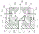
Fig. 1 is a schematic structural diagram of the present invention.
In the drawing, 1 is a die holder, 2 is a lower die, 3 is an upper die, 4 is a forging and pressing table, 5 is a backing plate, 6 is an ejector rod, 7 is a groove I, 8 is a groove II, 9 is a first cavity, 10 is a second cavity, 11 is a third cavity, 12 is a fourth cavity, 13 is a through hole I, 14 is a horizontal punch, 15 is a through hole II, 16 is a vertical punch, 17 is a through hole III, 18 is a limiting column, and 19 is a limiting groove.
Detailed Description
The technical solutions in the embodiments of the present invention will be described clearly and completely with reference to the accompanying drawings in the embodiments of the present invention, and it is obvious that the described embodiments are only some embodiments of the present invention, not all embodiments. Based on the embodiments in the present invention, all other embodiments obtained by a person skilled in the art without any creative effort belong to the protection scope of the present invention.
As shown in fig. 1, the utility model provides a well head pressure locomotive valves forge and press seat for oil development, including die holder 1, be equipped with lower mould 2 on the die holder 1, 2 swing joint of lower mould have last mould 3, 2 internalization of lower mould are equipped with forge and press platform 4, lower mould 2, go up mould 3 and forge and press platform 4 on all be equipped with valve body assorted die cavity structure, die cavity structure is used for placing the valve body, cooperatees through last mould, lower mould and forging and pressing platform for the valve body forging forge piece is forged and is formed. Specifically, a first cavity 9 is arranged on the forging and pressing table 4, two second cavities 10 are arranged on the lower die 2, the two second cavities 10 are respectively arranged on two sides of the first cavity 9, a third cavity 11 and two fourth cavities 12 are arranged on the upper die 3, the two fourth cavities 12 are respectively arranged on two sides of the third cavity 11, the first cavity 9 and the third cavity 11 are correspondingly arranged and are matched with the middle of the valve body, the second cavity 10 and the fourth cavity 12 are correspondingly arranged and are matched with two end portions of the valve body, namely, the first cavity 9 and the third cavity 11 are used for forging and pressing the middle of the valve body, the second cavity 10 and the fourth cavity 12 are used for forging and pressing the two end portions of the valve body, and the specific shapes of the first cavity 9, the second cavity 10, the third cavity 11 and the fourth cavity 12 can be designed according to the shape structure of the valve body.
And a backing plate 5 is arranged between the lower die 2 and the die holder 1, and the backing plate 5 can play a certain protection role on the die holder 1. Be equipped with on the die holder 1 with 2 assorted recesses I7 of lower mould, backing plate 5 sets up in the bottom of recess I7, and lower mould 2 sets up in recess I7 and is located backing plate 5, and recess I7 is used for fixing and spacing lower mould 2, prevents that forging and pressing in-process lower mould from breaking away from the die holder. Similarly, be equipped with in the lower mould 2 with forging and pressing 4 assorted recesses II 8, forging and pressing 4 activities of platform set up in recess II 8, recess II 8 are used for placing the forging and pressing platform and play limiting displacement to the forging and pressing platform. And the lower part of the die holder 1 is provided with an ejector rod 6 for pushing the forging platform 4 to move, and the ejector rod 6 can eject the forging platform 4 out of the lower die, so that the valve forging is separated from the lower die. Specifically, through holes III 17 matched with the ejector rods 6 are formed in the die holder 1, the base plate 5 and the lower die 2, the through holes III 17 and the grooves II 8 are coaxially arranged and communicated, the ejector rods 6 penetrate through the through holes III 17 and abut against the forging and pressing table 4 in the grooves II 8, then the ejector rods 6 are pushed upwards, and therefore the forging and pressing table 4 is ejected out, and the valve body forging is separated from the lower die.
The connection parts of the two sides of the upper die 3 and the lower die 2 are respectively provided with a through hole I13, and horizontal punches 14 matched with the two ends of the valve body are respectively arranged in the two through holes I13; go up to be equipped with on the mould 3 and perforate II 15, be equipped with in the perforation II 15 with the middle part assorted vertical drift 16 of valve body, horizontal drift 14 outer end and vertical drift 16 upper end all be connected with the forging press, through setting up horizontal drift 14 and vertical drift 16, make the valve body once forge when taking shape and take shape out the valve body hole, realize that material utilization is high, and improve production efficiency greatly. The two sides of the upper die 3 are respectively provided with a limiting column 18, the die holder 1 is provided with a limiting groove 19 matched with the limiting column 18, the limiting column 18 is movably arranged in the limiting groove 19, and the upper die 3 is prevented from moving relative to the lower die 2 and the die holder or being separated from the lower die in the forging process through the matching of the limiting column and the limiting groove, so that the forging effect of the valve body is ensured. The utility model discloses simple structure, it is easy and with low costs to make, convenient to use.
The above description is only a preferred embodiment of the present invention, and should not be taken as limiting the invention, and any modifications, equivalent replacements, improvements, etc. made within the spirit and principle of the present invention should be included in the protection scope of the present invention.
Claims (7)
1. The utility model provides a well head pressure locomotive valves forges and presses seat for oil development which characterized in that: the valve body forging die comprises a die holder (1), wherein a lower die (2) is arranged on the die holder (1), the lower die (2) is connected with an upper die (3), a forging platform (4) is movably arranged in the lower die (2), and cavity structures matched with a valve body are arranged on the lower die (2), the upper die (3) and the forging platform (4); a base plate (5) is arranged between the lower die (2) and the die holder (1), and an ejector rod (6) used for pushing the forging platform (4) to move is arranged at the lower part of the die holder (1).
2. The oil development well head pressure truck valve group forging seat according to claim 1, characterized in that: be equipped with on die holder (1) with lower mould (2) assorted recess I (7), backing plate (5) set up in the bottom of recess I (7), lower mould (2) set up in recess I (7) and lie in on backing plate (5).
3. The oil development wellhead pressure truck valve group forging seat as claimed in claim 1 or 2, characterized in that: a groove II (8) matched with the forging platform (4) is arranged in the lower die (2), and the forging platform (4) is movably arranged in the groove II (8).
4. The oil development wellhead pressure truck valve group forging seat as recited in claim 3, characterized in that: a first cavity (9) is arranged on the forging platform (4), two second cavities (10) are arranged on the lower die (2), and the two second cavities (10) are respectively arranged on two sides of the first cavity (9); the upper die (3) is provided with a third cavity (11) and two fourth cavities (12), and the two fourth cavities (12) are respectively arranged at two sides of the third cavity (11); first die cavity (9) and third die cavity (11) correspond the setting and all with the middle part phase-match of valve body, second die cavity (10) and fourth die cavity (12) correspond the setting and all with two tip phase-matches of valve body.
5. The oil development wellhead pressure truck valve group forging seat as recited in claim 4, characterized in that: the connection parts of the two sides of the upper die (3) and the lower die (2) are respectively provided with a through hole I (13), and horizontal punches (14) matched with the two ends of the valve body are respectively arranged in the two through holes I (13); and a punching hole II (15) is arranged on the upper die (3), and a vertical punch (16) matched with the middle part of the valve body is arranged in the punching hole II (15).
6. A wellhead pressure valve train forging seat for oil exploitation according to claim 1, 2, 4 or 5, wherein: die holder (1), backing plate (5) and lower mould (2) all are equipped with III (17) of perforation with ejector pin (6) assorted, and perforation III (17) and recess II (8) coaxial line set up and are linked together.
7. The oil development well head pressure truck valve group forging seat according to claim 6, characterized in that: the die is characterized in that limiting columns (18) are arranged on two sides of the upper die (3), limiting grooves (19) matched with the limiting columns (18) are formed in the die holder (1), and the limiting columns (18) are movably arranged in the limiting grooves (19).
Priority Applications (1)
| Application Number | Priority Date | Filing Date | Title |
|---|---|---|---|
| CN202021225927.2U CN212598648U (en) | 2020-06-29 | 2020-06-29 | Well head pressure truck valves forges and presses seat for oil development |
Applications Claiming Priority (1)
| Application Number | Priority Date | Filing Date | Title |
|---|---|---|---|
| CN202021225927.2U CN212598648U (en) | 2020-06-29 | 2020-06-29 | Well head pressure truck valves forges and presses seat for oil development |
Publications (1)
| Publication Number | Publication Date |
|---|---|
| CN212598648U true CN212598648U (en) | 2021-02-26 |
Family
ID=74743104
Family Applications (1)
| Application Number | Title | Priority Date | Filing Date |
|---|---|---|---|
| CN202021225927.2U Active CN212598648U (en) | 2020-06-29 | 2020-06-29 | Well head pressure truck valves forges and presses seat for oil development |
Country Status (1)
| Country | Link |
|---|---|
| CN (1) | CN212598648U (en) |
Cited By (1)
| Publication number | Priority date | Publication date | Assignee | Title |
|---|---|---|---|---|
| CN116921612A (en) * | 2022-04-06 | 2023-10-24 | 温州良工锻造有限公司 | Special forging forming equipment for integral forging valve body of stop valve of power station and machining process of special forging forming equipment |
-
2020
- 2020-06-29 CN CN202021225927.2U patent/CN212598648U/en active Active
Cited By (1)
| Publication number | Priority date | Publication date | Assignee | Title |
|---|---|---|---|---|
| CN116921612A (en) * | 2022-04-06 | 2023-10-24 | 温州良工锻造有限公司 | Special forging forming equipment for integral forging valve body of stop valve of power station and machining process of special forging forming equipment |
Similar Documents
| Publication | Publication Date | Title |
|---|---|---|
| CN201644690U (en) | A Die for Partial Upsetting Forming of Metal Bar | |
| CN203887063U (en) | Forming, trimming and flanging combined die structure | |
| CN203003032U (en) | Precision forging extrusion die device | |
| CN203917609U (en) | Passenger car bottom girder drawing flanging composite die | |
| CN203356370U (en) | Die mechanism capable of finishing side punching in process of turning upwards and downwards | |
| CN203764734U (en) | Fine-blanking extrusion die of star wheel of clutch | |
| CN109482739A (en) | Formed punch blank holder integrated mould | |
| CN203695834U (en) | Energy-saving drilling tool block press | |
| CN112756538A (en) | Near-net forming die and method for forging hinge beam of refined steel stone pressure equipment | |
| CN204565028U (en) | Two flange forge piece forming combination die | |
| CN203304422U (en) | Improved casting wheel mold | |
| CN203936261U (en) | A kind of diel | |
| CN202825949U (en) | Press-fit double-punching die | |
| CN206185005U (en) | Many tapered wedge structure of press die | |
| CN208495682U (en) | Valve body forging mold | |
| CN213223943U (en) | Stamping die for forming inductor | |
| CN205217772U (en) | Punching a hole of braking oil pipe support baffle, impression mould | |
| CN204842615U (en) | It is high -efficient towards breach mould | |
| CN203972592U (en) | A kind of clutch star-wheel essence impact extrusion compression mould | |
| CN214977465U (en) | Die structure of character cut in bas-relief forging | |
| CN215786082U (en) | Multi-purpose punching die with good compatibility | |
| CN221983805U (en) | A die for producing aerospace support forgings | |
| CN203253814U (en) | Shaping and punching integrated die | |
| CN204817522U (en) | Bore bit calor innatus processing forming die | |
| CN217617548U (en) | Die for finish forging bevel gear applied to single-action press |
Legal Events
| Date | Code | Title | Description |
|---|---|---|---|
| GR01 | Patent grant | ||
| GR01 | Patent grant |