CN212560053U - Energy-saving plasticizer dealcoholizes device - Google Patents
Energy-saving plasticizer dealcoholizes device Download PDFInfo
- Publication number
- CN212560053U CN212560053U CN202021089932.5U CN202021089932U CN212560053U CN 212560053 U CN212560053 U CN 212560053U CN 202021089932 U CN202021089932 U CN 202021089932U CN 212560053 U CN212560053 U CN 212560053U
- Authority
- CN
- China
- Prior art keywords
- pipe
- plasticizer
- energy
- heat exchange
- saving
- Prior art date
- Legal status (The legal status is an assumption and is not a legal conclusion. Google has not performed a legal analysis and makes no representation as to the accuracy of the status listed.)
- Active
Links
- 239000004014 plasticizer Substances 0.000 title claims abstract description 19
- 239000000463 material Substances 0.000 claims abstract description 42
- LFQSCWFLJHTTHZ-UHFFFAOYSA-N Ethanol Chemical compound CCO LFQSCWFLJHTTHZ-UHFFFAOYSA-N 0.000 claims abstract description 19
- 238000010438 heat treatment Methods 0.000 claims description 22
- 239000000498 cooling water Substances 0.000 claims description 8
- 238000005192 partition Methods 0.000 claims description 8
- 239000007921 spray Substances 0.000 claims description 8
- 238000009833 condensation Methods 0.000 abstract description 7
- 230000005494 condensation Effects 0.000 abstract description 7
- 238000005265 energy consumption Methods 0.000 abstract description 4
- 238000004134 energy conservation Methods 0.000 abstract description 3
- 230000009467 reduction Effects 0.000 abstract description 3
- 238000011084 recovery Methods 0.000 abstract description 2
- 238000004064 recycling Methods 0.000 abstract description 2
- 238000000034 method Methods 0.000 description 8
- 230000008569 process Effects 0.000 description 7
- BJQHLKABXJIVAM-UHFFFAOYSA-N bis(2-ethylhexyl) phthalate Chemical group CCCCC(CC)COC(=O)C1=CC=CC=C1C(=O)OCC(CC)CCCC BJQHLKABXJIVAM-UHFFFAOYSA-N 0.000 description 4
- 125000004122 cyclic group Chemical group 0.000 description 4
- 239000004803 Di-2ethylhexylphthalate Substances 0.000 description 2
- 238000010521 absorption reaction Methods 0.000 description 2
- 230000000694 effects Effects 0.000 description 2
- 238000007789 sealing Methods 0.000 description 2
- 239000000126 substance Substances 0.000 description 2
- XLYOFNOQVPJJNP-UHFFFAOYSA-N water Substances O XLYOFNOQVPJJNP-UHFFFAOYSA-N 0.000 description 2
- 230000009471 action Effects 0.000 description 1
- 238000000889 atomisation Methods 0.000 description 1
- 239000012752 auxiliary agent Substances 0.000 description 1
- 230000008901 benefit Effects 0.000 description 1
- 238000006243 chemical reaction Methods 0.000 description 1
- 238000010586 diagram Methods 0.000 description 1
- 230000007613 environmental effect Effects 0.000 description 1
- 150000002148 esters Chemical class 0.000 description 1
- 229940011871 estrogen Drugs 0.000 description 1
- 239000000262 estrogen Substances 0.000 description 1
- BGOFCVIGEYGEOF-UJPOAAIJSA-N helicin Chemical compound O[C@@H]1[C@@H](O)[C@H](O)[C@@H](CO)O[C@H]1OC1=CC=CC=C1C=O BGOFCVIGEYGEOF-UJPOAAIJSA-N 0.000 description 1
- 230000008676 import Effects 0.000 description 1
- 230000010354 integration Effects 0.000 description 1
- 239000007788 liquid Substances 0.000 description 1
- 238000004519 manufacturing process Methods 0.000 description 1
- 238000006386 neutralization reaction Methods 0.000 description 1
- XNGIFLGASWRNHJ-UHFFFAOYSA-N phthalic acid Chemical class OC(=O)C1=CC=CC=C1C(O)=O XNGIFLGASWRNHJ-UHFFFAOYSA-N 0.000 description 1
- 239000002861 polymer material Substances 0.000 description 1
- 230000009967 tasteless effect Effects 0.000 description 1
- 230000009466 transformation Effects 0.000 description 1
- 238000005406 washing Methods 0.000 description 1
Images


Classifications
-
- Y—GENERAL TAGGING OF NEW TECHNOLOGICAL DEVELOPMENTS; GENERAL TAGGING OF CROSS-SECTIONAL TECHNOLOGIES SPANNING OVER SEVERAL SECTIONS OF THE IPC; TECHNICAL SUBJECTS COVERED BY FORMER USPC CROSS-REFERENCE ART COLLECTIONS [XRACs] AND DIGESTS
- Y02—TECHNOLOGIES OR APPLICATIONS FOR MITIGATION OR ADAPTATION AGAINST CLIMATE CHANGE
- Y02P—CLIMATE CHANGE MITIGATION TECHNOLOGIES IN THE PRODUCTION OR PROCESSING OF GOODS
- Y02P20/00—Technologies relating to chemical industry
- Y02P20/10—Process efficiency
-
- Y—GENERAL TAGGING OF NEW TECHNOLOGICAL DEVELOPMENTS; GENERAL TAGGING OF CROSS-SECTIONAL TECHNOLOGIES SPANNING OVER SEVERAL SECTIONS OF THE IPC; TECHNICAL SUBJECTS COVERED BY FORMER USPC CROSS-REFERENCE ART COLLECTIONS [XRACs] AND DIGESTS
- Y02—TECHNOLOGIES OR APPLICATIONS FOR MITIGATION OR ADAPTATION AGAINST CLIMATE CHANGE
- Y02P—CLIMATE CHANGE MITIGATION TECHNOLOGIES IN THE PRODUCTION OR PROCESSING OF GOODS
- Y02P20/00—Technologies relating to chemical industry
- Y02P20/50—Improvements relating to the production of bulk chemicals
-
- Y—GENERAL TAGGING OF NEW TECHNOLOGICAL DEVELOPMENTS; GENERAL TAGGING OF CROSS-SECTIONAL TECHNOLOGIES SPANNING OVER SEVERAL SECTIONS OF THE IPC; TECHNICAL SUBJECTS COVERED BY FORMER USPC CROSS-REFERENCE ART COLLECTIONS [XRACs] AND DIGESTS
- Y02—TECHNOLOGIES OR APPLICATIONS FOR MITIGATION OR ADAPTATION AGAINST CLIMATE CHANGE
- Y02P—CLIMATE CHANGE MITIGATION TECHNOLOGIES IN THE PRODUCTION OR PROCESSING OF GOODS
- Y02P70/00—Climate change mitigation technologies in the production process for final industrial or consumer products
- Y02P70/10—Greenhouse gas [GHG] capture, material saving, heat recovery or other energy efficient measures, e.g. motor control, characterised by manufacturing processes, e.g. for rolling metal or metal working
Landscapes
- Vaporization, Distillation, Condensation, Sublimation, And Cold Traps (AREA)
Abstract
The utility model discloses an energy-saving plasticizer dealcoholization device, which comprises an inner barrel body, wherein an outer barrel body is sleeved outside the inner barrel body, a coaxially arranged return pipe is sleeved inside the inner barrel body, an inverted cone-shaped guide cylinder is installed at the top end of the return pipe, a plurality of annular clapboards which are arranged at equal intervals are arranged between the outer part of a main body of the return pipe and the inner wall of the inner barrel body, heat exchange cavities are respectively arranged between adjacent annular clapboards, between the annular clapboards and the guide cylinder, and between the annular clapboards and a bottom plate of the inner barrel body, and the adjacent heat exchange cavities are communicated; a vacuum heat conduction pipe is arranged on the wall of the heat exchange cavity, the inner end of the vacuum heat conduction pipe penetrates through the heat exchange cavity, and the outer end of the vacuum heat conduction pipe is positioned in a clamping cavity between the inner cylinder body and the outer cylinder body; the dealcoholization device provided by the utility model can preheat the materials by recycling the condensation heat, reduce the dealcoholization energy consumption and realize energy conservation and emission reduction; the dealcoholization and the recovery of alcohol are integrally arranged, and the structure is compact and reasonable.
Description
Technical Field
The utility model relates to an energy-saving plasticizer dealcoholizes device belongs to chemical industry equipment technical field.
Background
The plasticizer is a high polymer material auxiliary agent and also phthalate esters in environmental estrogen, and the plasticizer is various in variety, and the most common variety is DEHP. The chemical name of DEHP is di (2-ethylhexyl) phthalate, which is a colorless and tasteless liquid and is widely applied in industry.
In the production process of the plasticizer, because excessive alcohol is added in the alcoholization reaction, a certain amount of water and excessive alcohol are contained in the crude ester after neutralization and water washing, and further removal is needed, and the dealcoholization method in the prior art comprises the following steps: placing the materials in a closed dealcoholization kettle, and separating out excessive alcohol in the plasticizer by adopting a reduced pressure stripping mode; the energy consumption of the mode is high, and the mode does not accord with the current national energy-saving and emission-reducing policy; the gaseous alcohol that deviates from is not convenient for retrieve, needs additionally to use other auxiliary devices such as condenser for overall structure is not compact.
In view of the above, the prior art is obviously inconvenient and disadvantageous in practical use, and needs to be improved.
SUMMERY OF THE UTILITY MODEL
The technical problem to be solved by the utility model is to provide an energy-saving plasticizer dealcoholization device, which can preheat materials by recycling condensation heat, reduce dealcoholization energy consumption and realize energy conservation and emission reduction; the dealcoholization and the recovery of alcohol are integrally arranged, and the structure is compact and reasonable.
For solving the technical problem, the utility model discloses a following technical scheme:
an energy-saving plasticizer dealcoholization device comprises an inner barrel, wherein an outer barrel is sleeved outside the inner barrel, a coaxially arranged return pipe is sleeved inside the inner barrel, an inverted cone-shaped guide cylinder is installed at the top end of the return pipe, a plurality of annular partition plates which are arranged at equal intervals are arranged between the outer part of a main body of the return pipe and the inner wall of the inner barrel, heat exchange chambers are respectively arranged between adjacent annular partition plates, between the annular partition plates and the guide cylinder, and between the annular partition plates and a bottom plate of the inner barrel, and the adjacent heat exchange chambers are communicated; the bottom of the heat exchange cavity at the lowest part is provided with a material inlet, and the heat exchange cavity at the highest part is communicated with the lower end of the guide pipe; the wall of the heat exchange cavity is provided with a vacuum heat conduction pipe, the inner end of the vacuum heat conduction pipe penetrates through the heat exchange cavity, the outer end of the vacuum heat conduction pipe is located in a clamping cavity between the inner barrel and the outer barrel, and a fin is arranged on a main body at the outer end of the vacuum heat conduction pipe.
Furthermore, the guide pipe is right-angled, a plurality of spray heads arranged downwards are mounted on the guide pipe, and the spray heads are communicated with the guide pipe.
Furthermore, a spiral heating pipe is arranged right below the spray head, one end of the heating pipe is provided with a heating medium inlet, and one end of the heating pipe is provided with a heating medium outlet.
Further, the bottom of the inner cylinder body is sealed, and the top of the inner cylinder body is opened.
Furthermore, the height of the return pipe is smaller than that of the inner cylinder, and the lower end of the return pipe is communicated with the material outlet.
Further, the height of outer barrel is greater than the height of interior barrel, and the head is installed at the top of outer barrel, and the main part outside of outer barrel is provided with the clamp cover, and the clamp cover communicates with cooling water inlet and cooling water outlet respectively.
Further, the bottom of the clamping cavity between the outer cylinder and the inner cylinder is provided with a recovered alcohol outlet.
Furthermore, the material inlet is connected with a pump, and the pump pumps the material to be dealcoholized into the heat exchange cavity from the material inlet.
The utility model adopts the above technical scheme after, compare with prior art, have following advantage:
the utility model provides a dealcoholize device, the material reachs the shower nozzle department under the effect of pipe and atomizes, the material is heated and dealcoholize to the heating pipe in the atomizing process, the material after dealcoholize loops through back flow and material export after being collected by the draft tube and derives, the gaseous state alcohol that deviates from gets into the clamp intracavity between interior barrel and the outer barrel and condenses, the fin that sets up on the outer end of vacuum heat pipe and the outer end in the condensing process absorbs the heat, make gaseous state alcohol condense, the heat that vacuum heat pipe outer end absorbed transmits the inner of vacuum heat pipe, the inner of vacuum heat pipe is located the heat transfer chamber, the inner of vacuum heat pipe makes the interior material that waits to dealcoholize of heat transfer chamber heat warm up and preheat, through the heat absorption and release processes of the vacuum heat conduction pipe, the condensation heat is recycled to preheat the materials, the dealcoholization energy consumption can be reduced, and the energy conservation and emission reduction are realized; the utility model discloses a setting of an interior urceolus for dealcoholize and retrieve the integration setting of mellow wine, compact structure is reasonable.
The present invention will be described in detail with reference to the accompanying drawings and examples.
Drawings
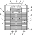
Fig. 1 is a schematic structural diagram of the present invention;
FIG. 2 is a cross-sectional view taken at A-A of FIG. 1;
FIG. 3 is a schematic view of the internal structure of the inner cylinder;
in the figure, 1-an inner cylinder, 2-a return pipe, 3-a clapboard, 4-a guide cylinder, 5-a heat exchange chamber, 6-a material inlet, 7-a material outlet, 8-a vacuum heat conduction pipe, 81-a fin, 9-a guide pipe, 10-a spray head, 11-a heating pipe, 12-a heating medium inlet, 13-a heating medium outlet, 14-an outer cylinder, 15-an end enclosure, 16-a jacket, 17-a cooling water inlet, 18-a cooling water outlet and 19-a recovered alcohol outlet.
Detailed Description
In order to clearly understand the technical features, objects, and effects of the present invention, embodiments of the present invention will be described with reference to the accompanying drawings.
As figure 1, figure 2 and figure 3 are shown jointly, the utility model provides an energy-saving plasticizer dealcoholize device, including interior barrel 1, the bottom of interior barrel 1 carries out the shutoff, the open setting in top, the inside cover of interior barrel 1 is equipped with the back flow 2 of coaxial setting, the height of barrel 1 in highly being less than of back flow 2, the low side and the material export 7 of back flow 2 are linked together, the draft tube 4 of back taper is installed on the top of back flow 2, draft tube 4 is used for collecting the material after dealcoholizing, be provided with the cyclic annular baffle 3 of a plurality of equidistant settings between the main part outside of back flow 2 and the interior barrel 1 inner wall, between the adjacent cyclic annular baffle 3, between cyclic annular baffle 3 and the draft tube 4, be provided with heat transfer chamber 5 between cyclic annular baffle 3 and the interior barrel 1 bottom plate respectively, communicate between the adjacent heat transfer chamber 5.
The bottom of the heat exchange chamber 5 at the lowest part is provided with a material inlet 6, the material inlet 6 is connected with a pump, the pump pumps the material to be dealcoholized into the heat exchange chamber 5 from the material inlet 6, and the material flows in the heat exchange chamber 5 from bottom to top; the heat exchange cavity 5 of the top communicates with the lower extreme of pipe 9, pipe 9 sets up in the space between draft tube 4 and the 1 inner wall of interior barrel, pipe 9 is the right angle form, install the shower nozzle 10 that a plurality of set up down on the pipe 9, shower nozzle 10 communicates with pipe 9, shower nozzle 10 is used for atomizing the material of waiting to dealcoholize, be provided with spiral helicine heating pipe 11 under the shower nozzle 10, the one end of heating pipe 11 is provided with heating medium import 12, the one end of heating pipe 11 is provided with heating medium export 13, heating pipe 11 is used for heating the material after the atomizing and dealcoholize.
The wall of the heat exchange chamber 5 is provided with vacuum heat conduction pipes 8 which are uniformly distributed on the circumference, the inner ends of the vacuum heat conduction pipes 8 penetrate through the heat exchange chamber 5, the outer ends of the vacuum heat conduction pipes 8 are positioned in a clamping cavity between the inner barrel 1 and the outer barrel 14, and a main body at the outer ends of the vacuum heat conduction pipes 8 is provided with fins 81 for absorbing heat; the outer end of the vacuum heat conduction pipe 8 is used for absorbing heat, and the inner end of the vacuum heat conduction pipe is used for preheating a material to be dealcoholized.
An outer cylinder body 14 is sleeved outside the inner cylinder body 1, the height of the outer cylinder body 14 is larger than that of the inner cylinder body 1, and a sealing head 15 for sealing is installed at the top of the outer cylinder body 14; a jacket 16 is arranged outside the main body of the outer cylinder 14, and the jacket 16 is respectively communicated with a cooling water inlet 17 and a cooling water outlet 18; a recovered alcohol outlet 19 is arranged at the bottom of the clamping cavity between the outer cylinder 14 and the inner cylinder 1; the clamping cavity between the outer cylinder 14 and the inner cylinder 1 is used for condensing the removed gaseous alcohol, and in the process of condensing the gaseous alcohol, the outer end of the vacuum heat conduction pipe 8 absorbs heat and transfers the heat to the heat exchange chamber 5 to preheat the material; jacket 16 serves to assist in condensation.
The utility model discloses a concrete theory of operation:
the material to be dealcoholized is pumped into the heat exchange chamber 5 at the lowest from the material inlet 6, the material flows in each heat exchange chamber 5 from bottom to top, the material reaches the spray head 10 under the action of the guide pipe 9 to be atomized, the heating pipe 11 heats the material to dealcoholize in the material atomization process, the dealcoholized material is collected by the guide cylinder 4 and then is led out through the return pipe 2 and the material outlet 7 in sequence, the separated gaseous alcohol enters a clamping cavity between the inner cylinder and the outer cylinder 14 from the top of the inner cylinder 1 to be condensed, the outer end of the vacuum heat conduction pipe 8 and fins 81 arranged on the outer end absorb heat in the condensation process, the gaseous alcohol is condensed, the heat absorbed by the outer end of the vacuum heat conduction pipe 8 is transmitted to the inner end of the vacuum heat conduction pipe 8, the inner end of the vacuum heat conduction pipe 8 is positioned in the heat exchange chamber 5, and the inner end of the vacuum heat conduction pipe 8 heats the material to; the jacket 16 is arranged to realize the complete condensation of the removed gaseous alcohol, and the condensed alcohol is discharged from the recovered alcohol outlet 19; the utility model discloses a heat absorption and the exothermal process of vacuum heat pipe 8, the preheating to the material is realized to recycle condensation heat.
The foregoing is illustrative of the best mode of the invention, and details not described herein are within the common general knowledge of a person of ordinary skill in the art. The protection scope of the present invention is subject to the content of the claims, and any equivalent transformation based on the technical teaching of the present invention is also within the protection scope of the present invention.
Claims (8)
1. An energy-saving plasticizer dealcoholizes device which characterized in that: the heat exchange device comprises an inner cylinder (1), wherein an outer cylinder (14) is sleeved outside the inner cylinder (1), a backflow pipe (2) which is coaxially arranged is sleeved inside the inner cylinder (1), an inverted cone-shaped guide cylinder (4) is installed at the top end of the backflow pipe (2), a plurality of annular partition plates (3) which are arranged at equal intervals are arranged between the outer part of a main body of the backflow pipe (2) and the inner wall of the inner cylinder (1), heat exchange chambers (5) are respectively arranged between adjacent annular partition plates (3), between the annular partition plates (3) and the guide cylinder (4), and between the annular partition plates (3) and a bottom plate of the inner cylinder (1), and adjacent heat exchange chambers (5) are communicated; the bottom of the heat exchange chamber (5) at the lowest part is provided with a material inlet (6), and the heat exchange chamber (5) at the uppermost part is communicated with the lower end of the guide pipe (9); the wall mounting of heat transfer chamber (5) has vacuum heat pipe (8), and inside heat transfer chamber (5) were worn to establish in the inner of vacuum heat pipe (8), and the outer end of vacuum heat pipe (8) is located the double-layered intracavity between interior barrel (1) and outer barrel (14), is provided with fin (81) on the main part of vacuum heat pipe (8) outer end.
2. The energy-saving plasticizer dealcoholization apparatus according to claim 1, wherein: the guide pipe (9) is right-angled, a plurality of spray heads (10) arranged downwards are mounted on the guide pipe (9), and the spray heads (10) are communicated with the guide pipe (9).
3. The energy-saving plasticizer dealcoholization apparatus according to claim 2, wherein: a spiral heating pipe (11) is arranged right below the spray head (10), a heating medium inlet (12) is arranged at one end of the heating pipe (11), and a heating medium outlet (13) is arranged at one end of the heating pipe (11).
4. The energy-saving plasticizer dealcoholization apparatus according to claim 1, wherein: the bottom of the inner cylinder body (1) is blocked, and the top is opened.
5. The energy-saving plasticizer dealcoholization apparatus according to claim 1, wherein: the height of the return pipe (2) is less than that of the inner cylinder (1), and the lower end of the return pipe (2) is communicated with the material outlet (7).
6. The energy-saving plasticizer dealcoholization apparatus according to claim 1, wherein: the height of the outer cylinder (14) is larger than that of the inner cylinder (1), the top of the outer cylinder (14) is provided with an end enclosure (15), the outer part of the main body of the outer cylinder (14) is provided with a jacket (16), and the jacket (16) is respectively communicated with a cooling water inlet (17) and a cooling water outlet (18).
7. The energy-saving plasticizer dealcoholization apparatus according to claim 1, wherein: and a recovered alcohol outlet (19) is formed in the bottom of the clamping cavity between the outer cylinder (14) and the inner cylinder (1).
8. The energy-saving plasticizer dealcoholization apparatus according to claim 1, wherein: the material inlet (6) is connected with a pump, and the pump pumps the material into the heat exchange chamber (5) from the material inlet (6).
Priority Applications (1)
| Application Number | Priority Date | Filing Date | Title |
|---|---|---|---|
| CN202021089932.5U CN212560053U (en) | 2020-06-15 | 2020-06-15 | Energy-saving plasticizer dealcoholizes device |
Applications Claiming Priority (1)
| Application Number | Priority Date | Filing Date | Title |
|---|---|---|---|
| CN202021089932.5U CN212560053U (en) | 2020-06-15 | 2020-06-15 | Energy-saving plasticizer dealcoholizes device |
Publications (1)
| Publication Number | Publication Date |
|---|---|
| CN212560053U true CN212560053U (en) | 2021-02-19 |
Family
ID=74634669
Family Applications (1)
| Application Number | Title | Priority Date | Filing Date |
|---|---|---|---|
| CN202021089932.5U Active CN212560053U (en) | 2020-06-15 | 2020-06-15 | Energy-saving plasticizer dealcoholizes device |
Country Status (1)
| Country | Link |
|---|---|
| CN (1) | CN212560053U (en) |
-
2020
- 2020-06-15 CN CN202021089932.5U patent/CN212560053U/en active Active
Similar Documents
| Publication | Publication Date | Title |
|---|---|---|
| CN210921791U (en) | Energy-concerving and environment-protective new forms of energy fire burning furnace | |
| CN108558629A (en) | A kind of production system and production method of refined cyclohexanone | |
| CN209685646U (en) | A kind of production system refining cyclohexanone | |
| CN205925051U (en) | Solvent recovery device | |
| CN204509240U (en) | A kind of leaching miscella evaporation waste heat twin-stage recycle device | |
| CN106267864B (en) | A kind of high-efficiency evaporator and adiponitrile process for refining for adiponitrile purification | |
| CN206285507U (en) | A kind of high-efficiency evaporator refined for adiponitrile | |
| CN106746118A (en) | A kind of system and method for utilization heat recovery from sewage alcohol ketone | |
| CN217828915U (en) | A environmental protection and energy saving type retort heat cycle subassembly for zinc powder production | |
| CN218709311U (en) | Abandonment cleaner distillation recovery unit | |
| CN209005253U (en) | A kind of production polyether polyol device for recovering tail gas | |
| CN212523086U (en) | Tail gas collecting tank for photoinitiator device | |
| CN214861267U (en) | Rectifying tower | |
| CN216324237U (en) | Circulating water cooling device of pipe production line | |
| CN215841663U (en) | Waste heat recovery device for oxalyl chloride rectifying tower | |
| CN212663149U (en) | Recovery processing device containing toluene industrial waste gas | |
| CN204815749U (en) | Solvent recovery unit in tail gas | |
| CN201264916Y (en) | Deamination tower for processing DMF rectification column top wastewater | |
| CN212417903U (en) | Tail gas processing apparatus of silicone adhesive production process | |
| CN216418354U (en) | But rapid cooling's rectifying column for chemical production | |
| CN209872898U (en) | Flat type vapour and liquid separator | |
| CN206295615U (en) | A kind of ethanol reclaims equipment for purifying | |
| CN113559537A (en) | A high-purity organic solvent recycling system | |
| CN217367196U (en) | Novel distillation column is used in 1, 4-butanediol preparation | |
| CN211255861U (en) | Soapstock modulation system |
Legal Events
| Date | Code | Title | Description |
|---|---|---|---|
| GR01 | Patent grant | ||
| GR01 | Patent grant |