CN212554214U - Even perforating device of textile fabric - Google Patents
Even perforating device of textile fabric Download PDFInfo
- Publication number
- CN212554214U CN212554214U CN202020624866.0U CN202020624866U CN212554214U CN 212554214 U CN212554214 U CN 212554214U CN 202020624866 U CN202020624866 U CN 202020624866U CN 212554214 U CN212554214 U CN 212554214U
- Authority
- CN
- China
- Prior art keywords
- fixedly connected
- frame body
- sliding
- wheel
- rod
- Prior art date
- Legal status (The legal status is an assumption and is not a legal conclusion. Google has not performed a legal analysis and makes no representation as to the accuracy of the status listed.)
- Expired - Fee Related
Links
Images


Abstract
The utility model discloses an even perforating device of textile fabric, the fruit pick-up device comprises a frame body, framework inner chamber bottom center department fixedly connected with electric telescopic handle, electric telescopic handle top fixedly connected with brace table, a plurality of mouth of punching has been seted up on the brace table, be equipped with first diaphragm, two about the framework first diaphragm uses the center of framework to be the bilateral symmetry setting as the central line, first diaphragm one end fixed connection is on the lateral wall of framework, two fixedly connected with first riser on the first diaphragm, first riser rear end face has unreels the wheel through pivot swing joint, the terminal surface has first round wheel through pivot swing joint before the first riser, another rear end face swing joint of first riser has the rolling wheel. The utility model discloses a series of structures make this device have the limit and receive characteristics such as material limit and punch.
Description
Technical Field
The utility model relates to a textile material technical field specifically is an even perforating device of textile material.
Background
The textile is a product formed by processing and weaving textile fibers, which is divided into two categories of woven fabric and knitted fabric, and China is one of the earliest countries in the world for producing textiles. China is a large country for textile production and export, the textile industry per se of China develops for many years, the competitive advantage is very obvious, the most complete industrial chain in the world is provided, the highest processing matching level is achieved, the self-adjusting capacity of a plurality of developed industry clusters for dealing with market risks is continuously enhanced, the steady development pace of the industry is kept, the textile needs to be punched in the production process, punching of part of cloth is required to be conducted in an equidistant and continuous mode, punching is usually conducted after manual measurement, certain errors exist in manual operation, punching precision is low, the expected effect cannot be achieved, and cloth waste is easily caused.
Disclosure of Invention
The utility model provides a technical problem lie in overcoming prior art's manual operation, have certain error, lead to the punching precision low, can not reach anticipated effect, cause the extravagant defect of cloth easily, provide an even perforating device of textile fabric. An even perforating device of textile material has and leads to the precision height that punches, reaches anticipated effect, is difficult to cause characteristics such as cloth waste.
In order to achieve the above object, the utility model provides a following technical scheme: a textile fabric uniform punching device comprises a frame body, wherein an electric telescopic rod is fixedly connected at the center of the bottom end of an inner cavity of the frame body, a supporting table is fixedly connected at the top end of the electric telescopic rod, a plurality of punching holes are formed in the supporting table, first transverse plates are arranged on the left side and the right side of the frame body, the two first transverse plates are arranged in a bilateral symmetry mode by taking the center of the frame body as a central line, one end of each first transverse plate is fixedly connected to the side wall of the frame body, a first vertical plate is fixedly connected to the two first transverse plates, the rear end face of each first vertical plate is movably connected with a unwinding wheel through a rotating shaft, the front end face of each first vertical plate is movably connected with a first round wheel through a rotating shaft, the other rear end face of each first vertical plate is movably connected with a winding wheel, the front end face of each first round wheel is movably connected with a, just first spout fixed connection is on the lateral wall of framework, two first spout inner chamber sliding connection has first slider, two first slider one side fixedly connected with first horizontal pole, the first motor of one of them fixedly connected with of first horizontal pole, the other fixedly connected with second spout of first horizontal pole, second spout inner chamber sliding connection has the second slider, second slider inner chamber fixedly connected with nut, the motor shaft fixedly connected with threaded rod of first horizontal pole one end is kept away from to first motor, the threaded rod passes second spout and nut in proper order, and extends to the second slider outside to through bearing swing joint on the second spout lateral wall, second slider bottom fixedly connected with puncher, the puncher bottom extends to the second spout outside, framework inner chamber top is equipped with transmission.
Preferably, the transmission device comprises a slide bar, the slide bar is fixedly connected to the top end of the frame body, the bottom end of the slide bar is fixedly connected with a fixed block, the slide bar is slidably connected with a third slide block, one side of the third slide block is fixedly connected with a second vertical plate, the right side of the second vertical plate is fixedly connected with a second cross rod, a plurality of tooth blocks are arranged below the second cross rod, the tooth blocks are fixedly connected to the second vertical plate, the rear end face of the frame body is fixedly connected with a second motor, a motor shaft of the second motor penetrates through the rear end face of the frame body and extends to the inner cavity of the frame body, and is fixedly connected with a gear, the front end face of the gear is fixedly connected with a third round wheel, the front end face of the gear is fixedly connected with a round block, the right side of the frame body is fixedly connected with a T-shaped rod, the bottom end of the T-, the third round wheel is connected with the fourth round wheel through a first belt in a transmission mode, the fifth round wheel is connected with the second round wheel through a second belt in a transmission mode, and the unwinding wheel is connected with the winding wheel through a cloth in a transmission mode.
Preferably, a plurality of the tooth blocks are combined into a saw-toothed shape, the tooth blocks are sequentially linearly arranged from top to bottom, and the cross section of each tooth block is triangular.
Preferably, the cloth and the support platform are mutually attached.
Preferably, the punching holes are the same in shape and size, and are distributed on the support table from left to right.
Compared with the prior art, the beneficial effects of the utility model are that: can pass through the framework, electric telescopic handle, a supporting bench, the drill way, first diaphragm, the riser, unreel the wheel, first round wheel, the rolling wheel, the second round wheel, first spout, first slider, first horizontal pole, first motor, the second spout, the second slider, the nut, the threaded rod, the puncher, transmission, the slide bar, the fixed block, the third slider, the second horizontal pole, the tooth piece, the second motor, the gear, the third round wheel, the circle piece, T shape pole, the fourth round wheel, the fifth round wheel, first belt, mutually support and use between second belt and the cloth, can carry out the equidistance to the cloth and punch, and punch the convenience, the simple operation.
Drawings
Fig. 1 is a schematic view of the overall structure of the present invention.
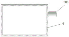
Fig. 2 is a side view of the second motor of the present invention.
Fig. 3 is an enlarged view of a portion a in fig. 1 according to the present invention.
Reference numbers in the figures: 1. a frame body; 2. an electric telescopic rod; 3. a support table; 4. punching an orifice; 5. a first transverse plate; 6. a first vertical plate; 7. unwinding wheels; 8. a first round wheel; 9. a winding wheel; 10. a second round wheel; 11. a first chute; 12. a first slider; 13. a first cross bar; 14. a first motor; 15. a second chute; 16. a second slider; 17. a nut; 18. a threaded rod; 19. a perforating machine; 20. a transmission device; 200. a slide bar; 201. a fixed block; 202. a third slider; 203. a second vertical plate; 204. a second cross bar; 205. a tooth block; 206. a second motor; 207. a gear; 208. a third round wheel; 209. a round block; 2090. a T-shaped rod; 2091. a fourth circular wheel; 2092. a fifth circular wheel; 2093. a first belt; 2094. a second belt; 2095. and (4) distributing.
Detailed Description
The technical solutions in the embodiments of the present invention will be described clearly and completely with reference to the accompanying drawings in the embodiments of the present invention, and it is obvious that the described embodiments are only some embodiments of the present invention, not all embodiments. Based on the embodiments in the present invention, all other embodiments obtained by a person skilled in the art without creative work belong to the protection scope of the present invention.
Referring to fig. 1-3, the present invention provides a technical solution: a uniform punching device for textile cloth comprises a frame body 1, an electric telescopic rod 2 is fixedly connected at the center of the bottom end of an inner cavity of the frame body 1, a supporting table 3 is fixedly connected at the top end of the electric telescopic rod 2, a plurality of punching holes 4 are arranged on the supporting table 3, the shapes and the sizes of the punching holes 4 are the same, the punching holes 4 are distributed on the supporting table 3 from left to right, first transverse plates 5 are arranged at the left and the right of the frame body 1, the two first transverse plates 5 are arranged in bilateral symmetry by taking the center of the frame body 1 as a central line, one end of each first transverse plate 5 is fixedly connected on the side wall of the frame body 1, first vertical plates 6 are fixedly connected on the two first transverse plates 5, the rear end surfaces of the first vertical plates 6 are movably connected with unwinding wheels 7 through rotating shafts, the front end surfaces of the first vertical plates 6 are movably connected with first round wheels 8 through rotating shafts, the, the inner cavity of the frame body 1 is provided with two first chutes 11, the first chutes 11 are arranged symmetrically left and right with the center of the frame body 1 as the central line, and the first chutes 11 are fixedly connected on the side wall of the frame body 1, the inner cavities of the two first chutes 11 are connected with first sliders 12 in a sliding manner, one side of the two first sliders 12 is fixedly connected with a first cross bar 13, one of the first cross bars 13 is fixedly connected with a first motor 14, the other one of the first cross bar 13 is fixedly connected with a second chute 15, the inner cavity of the second chute 15 is connected with a second slider 16 in a sliding manner, the inner cavity of the second slider 16 is fixedly connected with a nut 17, a motor shaft of one end of the first motor 14 far away from the first cross bar 13 is fixedly connected with a threaded rod 18, the threaded rod 18 sequentially passes through the second chute 15 and the nut 17 and extends to the outer side of the second slider 16 and is movably connected on, the bottom end of the perforating machine 19 extends to the outside of the second sliding chute 15, the top end of the inner cavity of the frame 1 is provided with a transmission device 20, the transmission device 20 comprises a sliding rod 200, the sliding rod 200 is fixedly connected to the top end of the frame 1, the bottom end of the sliding rod 200 is fixedly connected with a fixed block 201, the sliding rod 200 is slidably connected with a third sliding block 202, one side of the third sliding block 202 is fixedly connected with a second vertical plate 203, the right side of the second vertical plate 203 is fixedly connected with a second cross rod 204, a plurality of tooth blocks 205 are arranged below the second cross rod 204, the plurality of tooth blocks 205 are combined into a zigzag shape, the plurality of tooth blocks 205 are sequentially arranged in a linear manner from top to bottom, the cross section of each tooth block 205 is triangular, the tooth blocks 205 are fixedly connected to the second vertical plate 203, the rear end surface of the frame 1 is fixedly connected with a second motor 206, a motor shaft of the second motor 206 penetrates, fixedly connected with circle piece 209 on the terminal surface before the gear 207, 1 right side fixedly connected with T shape pole 2090 of framework, T shape pole 2090 bottom swing joint has fourth circle wheel 2091, terminal surface fixedly connected with fifth circle wheel 2092 before the fourth circle wheel 2091, be connected through first belt 2093 transmission between third circle wheel 208 and the fourth circle wheel 2091, be connected through second belt 2094 transmission between fifth circle wheel 2092 and the second circle wheel 10, be connected through cloth 2095 transmission between unreeling wheel 7 and the rolling wheel 9, cloth 2095 and supporting bench 3 are laminated each other, realize receiving the material while, the limit punches.
The working principle is as follows: when the utility model is used, the cloth is firstly placed on the unreeling wheel 7, then some cloth is wound on the reeling wheel 9, then the electric telescopic rod 2 is started, the electric telescopic rod 2 drives the supporting table 3 to move, when the supporting table 3 is mutually attached with the cloth 2095, the electric telescopic rod 2 is closed, then the distance of punching on the cloth 2095 by the punching machine 19 can be controlled through the first motor 14, the first motor 14 is started, the first motor 14 drives the threaded rod 18 to rotate, the threaded rod 18 drives the nut 17 to rotate, the nut 17 drives the second slider 16 to move, the second slider 16 drives the punching machine 19 to adjust, when the adjustment is completed, the first motor 14 is closed, then the second motor 206 and the punching machine 19 are started, the second motor 206 drives the gear 207 to rotate, the gear 207 respectively drives the tooth block 205, the round block 209 and the third round wheel 208 to rotate, the round block 209 drives the second cross rod 204 to move, the second cross bar 204 and the tooth block 205 drive the second vertical bar 203 to move upwards, the second vertical bar 203 drives the third sliding block 202 and the second sliding groove 15 to move respectively, the third sliding block 202 moves upwards on the sliding bar 200, the second sliding groove 15 drives the first cross bars 13 at two sides to move, the first cross bar 13 drives the first sliding block 12 to move upwards in the inner cavity of the first sliding groove 11, so that the punching machine 19 moves upwards, when the round block 209 and the gear 207 are far away from the tooth block 205 and the second cross bar 204, due to left and right gravity, the punching moves downwards to punch the cloth 2095, the second sliding groove 15 at the upper part moves downwards, the second sliding groove 15 drives the first cross bar 13 and the second vertical bar 203 at two sides to move downwards respectively, the first cross bar 13 drives the first sliding block 12 to slide downwards in the inner cavity of the first sliding groove 11, then the second vertical bar 203 drives the tooth block 205, the second cross bar 204 and the third sliding block 202 to move downwards, the third round wheel 208 drives the fourth round wheel 2091 to rotate through the first belt 2093, fourth round wheel 2091 drives fifth round wheel 2092 and rotates, fifth round wheel 2092 drives the rotation of second round wheel 10 through second belt 2094, second round wheel 10 drives wind-up wheel 9 and rolls the cloth of having beaten the hole, when gear 207 and circle 209 contact with second horizontal pole 204 and tooth piece 205, side punch 19 moves up, when gear 207 and circle 209 are kept away from second horizontal pole 204 and tooth piece 205, side punch 19 moves down, the device can realize the limit rolling of punching, and the hole distance on the cloth equals, thereby realize the equidistance and punch, when having beaten the hole, close second motor 206 and puncher 19, swing joint is on first riser 6 when having beaten the wind-up wheel 9 and unreeling wheel 7, can take off the cloth on unreeling wheel 7, it is above that the utility model discloses an all working processes.
Although embodiments of the present invention have been shown and described, it will be appreciated by those skilled in the art that changes, modifications, substitutions and alterations can be made in these embodiments without departing from the principles and spirit of the invention, the scope of which is defined in the appended claims and their equivalents.
Claims (5)
1. The utility model provides an even perforating device of textile fabric, includes framework (1), its characterized in that: the electric telescopic handle is characterized in that an electric telescopic handle (2) is fixedly connected to the center of the bottom end of an inner cavity of the frame body (1), a supporting table (3) is fixedly connected to the top end of the electric telescopic handle (2), a plurality of punching holes (4) are formed in the supporting table (3), first transverse plates (5) are arranged on the left side and the right side of the frame body (1), the two first transverse plates (5) are symmetrically arranged on the left side and the right side of the center line of the frame body (1), one end of each first transverse plate (5) is fixedly connected to the side wall of the frame body (1), first vertical plates (6) are fixedly connected to the two first transverse plates (5), unwinding wheels (7) are movably connected to the rear end faces of the first vertical plates (6) through rotating shafts, first round wheels (8) are movably connected to the front end faces of the first vertical plates (6) through rotating shafts, and, a second round wheel (10) is movably connected to the front end face of the frame body (1), two first sliding grooves (11) are arranged in the inner cavity of the frame body (1), the first sliding grooves (11) are arranged in a bilateral symmetry mode by taking the center of the frame body (1) as a central line, the first sliding grooves (11) are fixedly connected to the side wall of the frame body (1), the inner cavities of the two first sliding grooves (11) are connected with first sliding blocks (12) in a sliding mode, one side of each of the two first sliding blocks (12) is fixedly connected with a first cross rod (13), one of the first cross rods (13) is fixedly connected with a first motor (14), the other one of the first cross rods (13) is fixedly connected with a second sliding groove (15), the inner cavity of the second sliding groove (15) is connected with a second sliding block (16) in a sliding mode, the inner cavity of the second sliding block (16) is fixedly connected with a nut (17), and a threaded rod (18), the threaded rod (18) sequentially penetrates through the second sliding groove (15) and the nut (17), extends to the outer side of the second sliding block (16), and is movably connected to the side wall of the second sliding groove (15) through a bearing, a punching machine (19) is fixedly connected to the bottom end of the second sliding block (16), the bottom end of the punching machine (19) extends to the outer side of the second sliding groove (15), and a transmission device (20) is arranged at the top end of an inner cavity of the frame body (1).
2. A device for evenly perforating textile fabric according to claim 1, characterized in that: the transmission device (20) comprises a sliding rod (200), the sliding rod (200) is fixedly connected to the top end of the frame body (1), a fixed block (201) is fixedly connected to the bottom end of the sliding rod (200), a third sliding block (202) is slidably connected to the sliding rod (200), a second vertical plate (203) is fixedly connected to one side of the third sliding block (202), a second cross rod (204) is fixedly connected to the right side of the second vertical plate (203), a plurality of tooth blocks (205) are arranged below the second cross rod (204), the tooth blocks (205) are fixedly connected to the second vertical plate (203), a second motor (206) is fixedly connected to the rear end face of the frame body (1), a motor shaft of the second motor (206) penetrates through the rear end face of the frame body (1) and extends to the inner cavity of the frame body (1) and is fixedly connected with a gear (207), and a third round wheel (208) is fixedly connected to the front end, the winding frame is characterized in that a round block (209) is fixedly connected to the front end face of the gear (207), a T-shaped rod (2090) is fixedly connected to the right side of the frame body (1), a fourth round wheel (2091) is movably connected to the bottom end of the T-shaped rod (2090), a fifth round wheel (2092) is fixedly connected to the front end face of the fourth round wheel (2091), the third round wheel (208) is in transmission connection with the fourth round wheel (2091) through a first belt (2093), the fifth round wheel (2092) is in transmission connection with the second round wheel (10) through a second belt (2094), and the unwinding wheel (7) is in transmission connection with the winding wheel (9) through a cloth (2095).
3. A device for evenly perforating textile fabric according to claim 2, characterized in that: a plurality of the sawtooth blocks (205) are combined into a sawtooth shape, the sawtooth blocks (205) are sequentially linearly arranged from top to bottom, and the cross section of each sawtooth block (205) is triangular.
4. A device for evenly perforating textile fabric according to claim 1, characterized in that: the cloth (2095) is attached to the support table (3).
5. A device for evenly perforating textile fabric according to claim 1, characterized in that: the punching holes (4) are the same in shape and size, and the punching holes (4) are distributed on the supporting table (3) from left to right.
Priority Applications (1)
| Application Number | Priority Date | Filing Date | Title |
|---|---|---|---|
| CN202020624866.0U CN212554214U (en) | 2020-04-23 | 2020-04-23 | Even perforating device of textile fabric |
Applications Claiming Priority (1)
| Application Number | Priority Date | Filing Date | Title |
|---|---|---|---|
| CN202020624866.0U CN212554214U (en) | 2020-04-23 | 2020-04-23 | Even perforating device of textile fabric |
Publications (1)
| Publication Number | Publication Date |
|---|---|
| CN212554214U true CN212554214U (en) | 2021-02-19 |
Family
ID=74611300
Family Applications (1)
| Application Number | Title | Priority Date | Filing Date |
|---|---|---|---|
| CN202020624866.0U Expired - Fee Related CN212554214U (en) | 2020-04-23 | 2020-04-23 | Even perforating device of textile fabric |
Country Status (1)
| Country | Link |
|---|---|
| CN (1) | CN212554214U (en) |
Cited By (1)
| Publication number | Priority date | Publication date | Assignee | Title |
|---|---|---|---|---|
| CN113353677A (en) * | 2021-06-01 | 2021-09-07 | 宁波鑫泰生纺织科技有限公司 | Conveyer that cloth was used |
-
2020
- 2020-04-23 CN CN202020624866.0U patent/CN212554214U/en not_active Expired - Fee Related
Cited By (2)
| Publication number | Priority date | Publication date | Assignee | Title |
|---|---|---|---|---|
| CN113353677A (en) * | 2021-06-01 | 2021-09-07 | 宁波鑫泰生纺织科技有限公司 | Conveyer that cloth was used |
| CN113353677B (en) * | 2021-06-01 | 2022-06-28 | 宁波鑫泰生纺织科技有限公司 | Conveyer that cloth was used |
Similar Documents
| Publication | Publication Date | Title |
|---|---|---|
| CN212554214U (en) | Even perforating device of textile fabric | |
| CN107755507A (en) | A kind of hardware production and processing pressing equipment | |
| CN108271833A (en) | A kind of full-automatic dumpling wrapper production equipment | |
| CN204035250U (en) | T-steel level(l)ing machine | |
| CN109160377B (en) | A integration mechanical equipment for fabrics processing | |
| CN208856588U (en) | A kind of weaving cloth wrap-up | |
| CN216360543U (en) | Smooth treatment facility of heat preservation type polyester silk | |
| CN209831860U (en) | Micropore elastic material forming device that breathes freely | |
| CN210824692U (en) | Supporting roller frame of textile machine | |
| CN211310278U (en) | A lapping roller support frame for packaging film processing | |
| CN214983632U (en) | A flanging machine for plastic bag production | |
| CN215124746U (en) | Flatting mill for tailoring | |
| CN220316774U (en) | High-speed loom for preparing carbon fiber cloth | |
| CN211110196U (en) | Child base machine that stops | |
| CN219385536U (en) | Lapping machine is used in cotton production of quilting | |
| CN216297788U (en) | Improved generation skeleton supports horizontal ring integrated into one piece equipment | |
| CN215282151U (en) | Water hose cutting device for water purifier | |
| CN213864737U (en) | Cable winding device | |
| CN219405627U (en) | Die cutting machine for packaging bag production | |
| CN215970300U (en) | Paper cup processing device | |
| CN213061475U (en) | Forming device of heated board net cloth | |
| CN218707579U (en) | Winding machine for production of front-mounted filter screen | |
| CN213770765U (en) | Cloth winding device for producing spandex polyester fabric | |
| CN217191917U (en) | Silk screen groove forming press | |
| CN220000935U (en) | Flattening device is used in gauze mask production and processing |
Legal Events
| Date | Code | Title | Description |
|---|---|---|---|
| GR01 | Patent grant | ||
| GR01 | Patent grant | ||
| CF01 | Termination of patent right due to non-payment of annual fee |
Granted publication date: 20210219 |
|
| CF01 | Termination of patent right due to non-payment of annual fee |