Industrial robot electrical control teaching platform
Technical Field
The utility model relates to an electrical control technical field specifically is an industrial robot electrical control teaching platform.
Background
The electric control system is a combination of a plurality of electric elements and is used for controlling a certain object or objects, so that the controlled equipment can be safely and reliably operated.
The teaching platform is very extensive that uses in the teaching instrument again, and common teaching platform is a podium basically, places teaching articles for use and computer display on the mesa, and general teaching platform still need be equipped with the chair in addition, and the limitation of using is very big, and some can't be fine the presentation of the content of writing of need drawing on paper, the unable convenient and fast's of traditional teaching platform use, and the instrument on the teaching platform can fall very much dust along with the lapse of time.
SUMMERY OF THE UTILITY MODEL
An object of the utility model is to provide an industrial robot electrical control teaching platform to solve the problem that proposes in the above-mentioned background art.
In order to achieve the above object, the utility model provides a following technical scheme: an electric control teaching platform of an industrial robot comprises a shell, a moving block is movably arranged in the shell, a stool is fixedly arranged on one side of the moving block, wheels are fixedly arranged on one side of the stool, a push structure is fixedly arranged on one side of the stool, a slide projector is fixedly arranged on the top of the shell, a motor is fixedly arranged in the shell, an output end of the motor is fixedly provided with a telescopic rod, one end of the telescopic rod is fixedly provided with a connecting plate, one side of the connecting plate is fixedly provided with a display, the top of the shell is fixedly provided with a telescopic structure, one side of the telescopic structure is fixedly provided with a dust cover, the equipment cabinet is fixedly arranged inside the shell, the storage cabinet is fixedly arranged inside the shell, the drawer is fixedly arranged in the shell, and a control panel is fixedly arranged on one side of the shell.
The propelling movement structure, including first fixed block, one side fixed mounting of first fixed block has the connecting rod, the outer wall movable mounting of connecting rod has the slide bar, the outer wall movable mounting of slide bar has first slider, one side movable mounting of first slider has the dwang, the outer wall movable mounting of dwang has the spring, the outer wall movable mounting of dwang has the second slider, one side movable mounting of second slider has the second fixed block.
The telescopic structure comprises an electric rod, a first connecting block is fixedly mounted on the outer wall of the electric rod, a second connecting block is movably connected to one end of the first connecting block, a third connecting block is movably mounted to one end of the first connecting block, a fourth connecting block is movably mounted to one end of the third connecting block, and a fifth connecting block is movably mounted to one end of the second connecting block.
Preferably, the inner wall of the housing is provided with a sliding groove matched with the moving block, and one side of the pushing structure is connected with the inner wall of the housing.
Preferably, the number of the motors and the number of the telescopic rods are two, and the two motors and one end of each telescopic rod are fixedly connected with a connecting plate.
Preferably, the dustproof cover is a honeycomb curtain, and one end of the dustproof cover is connected with the inner wall of the shell.
Preferably, one end of the fourth connecting block and one end of the fifth connecting block are connected with one side of the dust cover.
Preferably, one side of the second fixed block is fixedly connected with the inner wall of the shell, and one side of the second fixed block is fixedly provided with a motor.
Compared with the prior art, the beneficial effects of the utility model are that: this industrial robot electrical control teaching platform, install the stool in the bottom of teaching platform, use the propelling movement structure to release the stool automatically, do not need manually completely, install the slide projector on the mesa, after the projector is connected to the slide projector, put paper on the slide projector, write on it and draw on all can be fine projection to the curtain, convenience more when teaching, and install the shield at the top of teaching platform, when need not using the teaching platform, open the shield through extending structure, prevent that the dust from dropping on the mesa of teaching platform.
Drawings
Fig. 1 is a schematic structural view of the present invention;
fig. 2 is a side view of the present invention;
FIG. 3 is a schematic view of the pushing structure of the present invention;
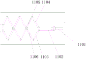
fig. 4 is a schematic view of the telescopic structure of the present invention.
In the figure: 1. a housing; 2. a moving block; 3. a stool; 4. a wheel; 5. a pushing structure; 501. a first fixed block; 502. a connecting rod; 503. a slide bar; 504. a first slider; 505. rotating the rod; 506. a spring; 507. a second slider; 508. a second fixed block; 6. a slide projector; 7. a motor; 8. a telescopic rod; 9. A connecting plate; 10. a display screen; 11. a telescopic structure; 1101. an electric rod; 1102. a first connection block; 1103. A second connecting block; 1104. a third connecting block; 1105. a fourth connecting block; 1106. a fifth connecting block; 12. a dust cover; 13. an equipment cabinet; 14. a storage cabinet; 15. a drawer; 16. a control panel.
Detailed Description
The technical solutions in the embodiments of the present invention will be described clearly and completely with reference to the accompanying drawings in the embodiments of the present invention, and it is obvious that the described embodiments are only some embodiments of the present invention, not all embodiments. Based on the embodiments in the present invention, all other embodiments obtained by a person skilled in the art without creative work belong to the protection scope of the present invention.
Referring to fig. 1-4, the present invention provides an embodiment: an industrial robot electrical control teaching platform comprises a shell 1, a movable block 2 is movably mounted inside the shell 1, a sliding groove matched with the movable block 2 is formed in the inner wall of the shell 1, one side of a pushing structure 5 is connected with the inner wall of the shell 1, a stool 3 is fixedly mounted on one side of the movable block 2, wheels 4 are fixedly mounted on one side of the stool 3, the pushing structure 5 is fixedly mounted on one side of the stool 3, a slide projector 6 is fixedly mounted at the top of the shell 1, a motor 7 is fixedly mounted inside the shell 1, the number of the motor 7 and two telescopic rods 8 are provided, two motors 7 and one end of each telescopic rod 8 are fixedly connected with a connecting plate 9, a telescopic rod 8 is fixedly mounted at the output end of the motor 7, a connecting plate 9 is fixedly mounted at one end of the telescopic rod 8, a display screen 10 is fixedly mounted at one side of the, one side fixed mounting of extending structure 11 has shield 12, shield 12 is the honeycomb blind, the one end of shield 12 is connected with shell 1's inner wall, shell 1's inside fixed mounting has equipment cabinet 13, shell 1's inside fixed mounting has locker 14, computer and other equipment can be put to equipment cabinet 13, locker 14 and drawer 15 are used for placing the teaching articles for use, shell 1's inside fixed mounting has drawer 15, one side fixed mounting of shell 1 has control panel 16.
The pushing structure 5 comprises a first fixed block 501, a connecting rod 502 is fixedly installed on one side of the first fixed block 501, a sliding rod 503 is movably installed on the outer wall of the connecting rod 502, the sliding rod 503 is connected with the stool 3, a first sliding block 504 is movably installed on the outer wall of the sliding rod 503, a rotating rod 505 is movably installed on one side of the first sliding block 504, a spring 506 is movably installed on the outer wall of the rotating rod 505, a second sliding block 507 is movably installed on the outer wall of the rotating rod 505, a second fixed block 508 is movably installed on one side of the second sliding block 507, one side of the second fixed block 508 is fixedly connected with the inner wall of the shell 1, a motor 7 is fixedly installed on one side of the second fixed block 508, the motor 7 is started to drive the second sliding block 507 to rotate, the second sliding block 507 drives the rotating rod 505, the rotating rod 505 drives the first sliding block 504, the spring 506, the slide bar 503 drives the stool 3.
Extending structure 11, including electronic pole 1101, the outer wall fixed mounting of electronic pole 1101 has first connecting block 1102, the one end swing joint of first connecting block 1102 has second connecting block 1103, the one end swing joint of first connecting block 1102 has third connecting block 1104, the one end swing joint of third connecting block 1104 has fourth connecting block 1105, the one end swing joint of second connecting block 1103 has fifth connecting block 1106, the junction of the one end swing joint fourth connecting block 1105 of electronic pole 1101 and fifth connecting block 1106, the one end of fourth connecting block 1105 and fifth connecting block 1106 is connected with one side of shield 12.
The working principle is as follows: the pushing structure 5 is started through the control panel 16, the motor 7 is started to drive the second sliding block 507 to rotate, the second sliding block 507 drives the rotating rod 505, the rotating rod 505 drives the first sliding block 504, the spring 506 assists the sliding rod 503 to move, the first sliding block 504 drives the sliding rod 503, the sliding rod 503 slides on the outer wall of the connecting rod 502, the sliding rod 503 drives the stool 3, the moving block 2 slides inside the housing 1 to push the stool 3 out or retract, the motor 7 drives the telescopic rod 8, the telescopic rod 8 drives the connecting plate 9, the connecting plate 9 drives the display screen 10 to ascend and descend, after the slide projector 6 is connected with the projector, paper is put on the slide projector 6, the pictures written on the paper can be well projected on the curtain, the slide projector 6 can be retracted, the equipment cabinet 13 can be put on a computer host and other equipment, the storage cabinet 14 and the drawer 15 are used for placing teaching articles, after the use, the telescopic structure 11 is started through the control panel 16, the electric rod 1101 drives the fourth connecting block 1105 and the fifth connecting block 1106, the fourth connecting block 1105 and the fifth connecting block 1106 drive the dust cover 12 to open and close, and the first connecting block 1102, the second connecting block 1103 and the third connecting block 1104 are used for connecting the fourth connecting block 1105 and the fifth connecting block 1106.
It will be evident to those skilled in the art that the invention is not limited to the details of the foregoing illustrative embodiments, and that the present invention may be embodied in other specific forms without departing from the spirit or scope of the present invention. Accordingly, the embodiments of the present invention are exemplary, and not limiting. The scope of the invention is indicated by the appended claims rather than by the foregoing description, and all changes that come within the meaning and range of equivalency of the claims are therefore intended to be embraced therein. Any reference sign in a claim should not be construed as limiting the claim concerned.