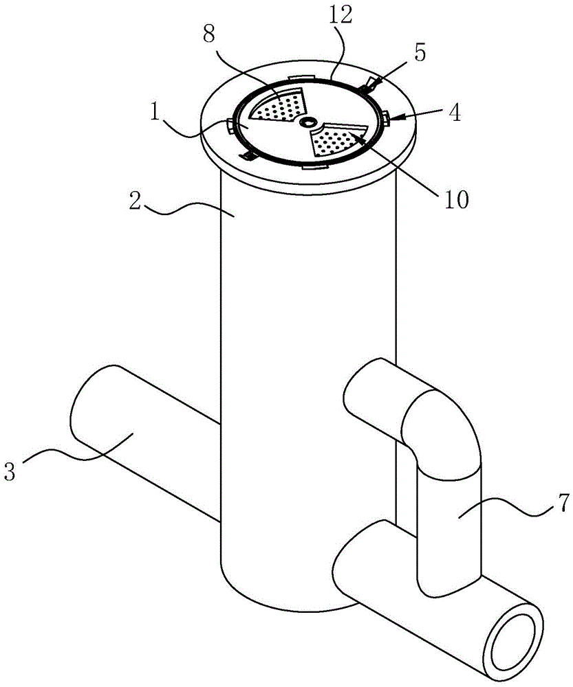
Municipal works drainage structures
Technical Field
The utility model belongs to the technical field of the technique of municipal works and specifically relates to a municipal works drainage structures is related to.
Background
The municipal facilities refer to various buildings, structures, equipment and the like which are arranged in planning and construction ranges of urban areas and towns (villages) and provide paid or unpaid public products and services for residents based on government responsibilities and obligations, and various public infrastructure constructions matched with urban life belong to the municipal engineering category, such as various pipelines closely related to life: construction of rain water, sewage, water supply, reclaimed water and the like. The catch basin is an important component of the urban drainage system, occupies an important position in the urban drainage system, has multiple distribution points and wide area, and plays a role in collecting and discharging rainwater on the surface of an urban area to avoid accumulated water accumulation in the city.
Chinese patent No. CN207829128U discloses a catch basin, which comprises a well body and a well cover installed under the ground, wherein the side wall of the well body is provided with an upstream hole and a downstream hole connected with a drainage pipe, when a flood occurs, the well cover is lifted up, so that rainwater flows into the well body and then is drained away through the drainage pipe.
The above prior art solutions have the following drawbacks: when the rainwater is too big, the displacement of well lid itself is less than the rainfall, makes the rainwater in time discharge, produces ponding easily and submerges the well lid, because hydraulic effect, leads to the well lid to outwards open very difficulty, the unable timely effectual drainage work that carries on.
SUMMERY OF THE UTILITY MODEL
Not enough to prior art exists, the utility model aims at providing a municipal works drainage structures has the well lid and opens convenient advantage.
The above utility model discloses an above-mentioned utility model purpose can realize through following technical scheme:
the utility model provides a municipal works drainage structures, includes well lid, the well body and drainage pipe, the well lid can slide at the internal vertical direction of well, the well head symmetry of the well body is equipped with two sets of hoisting device who is used for pulling up the well lid, the well head of the well body is provided with the limiting device who is used for restricting the well lid whereabouts, coaxial fixed being provided with the rand on the inner wall of the well body, the rand can restrict the well lid whereabouts with the contact of well lid bottom surface, be equipped with the flood discharge pipeline on the well body inner wall between the well head of rand and the well body, flood discharge pipeline one end and well body intercommunication, the other end and drainage.
By adopting the technical scheme, when the well lid is submerged by accumulated water, the limiting device on the well lid is opened, the well lid slides downwards under the action of gravity and water pressure, the well lid is not required to be lifted up manually, and the operation process is quicker and more labor-saving; the well lid does not fall after sliding to the position of the clamping ring, the flood discharge pipeline is exposed, accumulated water flows away from the flood discharge pipeline, and the effects of conveniently opening the well lid and improving the drainage efficiency are achieved; after the accumulated water is discharged, the well lid is pulled to the well mouth by using the lifting device, and the limiting device is closed to ensure that the well lid cannot slide downwards, so that the effect of conveniently and quickly discharging the whole water is realized.
The present invention may be further configured in a preferred embodiment as: the limiting device comprises a clamping ring and a plurality of clamping blocks, the clamping ring is coaxially rotated and arranged on the outer wall of the well cover, the clamping blocks are evenly and fixedly arranged on the outer wall of the clamping ring along the circumferential direction, a plurality of clamping grooves matched with the clamping blocks are formed in the well mouth of the well body along the circumferential direction, the clamping blocks can slide in the clamping grooves, a plurality of slide ways used for sliding the sliding blocks are arranged on the inner wall of the well body along the vertical direction, and the top ends of the slide ways are respectively communicated with the clamping grooves
By adopting the technical scheme, when water is accumulated, the clamping ring is rotated, the clamping ring drives the clamping block to enter the slideway from the clamping groove, so that the well cover slides into the well body under the action of gravity, and drainage is performed; after the drainage is accomplished, pull the well lid to the well head, rotate the pull ring and bring the fixture block into the draw-in groove, make the unable gliding of well lid.
The present invention may be further configured in a preferred embodiment as: lifting device includes first leading wheel, second leading wheel, cable wire and lift passageway, first leading wheel is fixed to be set up on the well lid, the lift passageway sets up on the inner wall of the well body along vertical direction, and shown lift passageway is used for supplying first leading wheel to reciprocate, lift passageway top is provided with accomodates the groove, the second leading wheel sets up on the lateral wall of accomodating the groove, the lateral wall of accomodating the groove is provided with the carousel that is used for the rolling cable wire, cable wire one end is fixed on the jackshaft of first leading wheel, the other end is walked around the second leading wheel and is fixed on the carousel after-passing first leading wheel, be provided with on the carousel and wave the handle, it is provided with the apron to dismantle on the groove to accomodate.
Through adopting above-mentioned technical scheme, when carrying and pulling the well lid, wave handle rolling cable wire, the assembly pulley that the cable wire constitutes through two leading wheels pulls up the well lid, makes the process of carrying and pulling the well lid more laborsaving, will lap after pulling the well lid, effectively avoids accomodating the groove and hindering passing vehicle and pedestrian in one's way.
The present invention may be further configured in a preferred embodiment as: a plurality of outlet have evenly been seted up along well lid circumference on the well lid, the coaxial rotation in bottom of well lid is provided with the filter disc that is used for the switching outlet.
By adopting the technical scheme, the exposed water outlet can be adjusted by rotating the handle on the filter disc, so that the water discharge amount is adjusted or the water outlet is closed according to the actual condition.
The present invention may be further configured in a preferred embodiment as: a plurality of drain holes are uniformly formed in the positions, corresponding to the water outlets, of the filter disc, and a handle for rotating the filter disc is hinged to a rotating shaft of the filter disc.
Through adopting above-mentioned technical scheme, when the well lid was closed, ponding still can discharge through the wash port, makes pedestrian and vehicle can not fall into the outlet when passing through and take place danger when having certain drainage ability.
The present invention may be further configured in a preferred embodiment as: the top of well lid is provided with warning circle, the bottom surface of warning circle is provided with two racks along vertical direction symmetry, the coaxial fixed gear that is provided with rack toothing of one end of second leading wheel, two the rack inserts lift passageway and meshes mutually with the gear.
By adopting the technical scheme, when the well lid falls, the steel cable drives the first guide wheel to rotate, the gear fixedly arranged on the guide wheel pushes the rack through meshing transmission, so that the warning ring is lifted, a warning effect is realized on passing vehicles and pedestrians, and the condition that the vehicles or the pedestrians fall into the well is effectively prevented; when the well lid is pulled up, the guide wheel rotates reversely, the gear pulls the rack through meshing transmission, and the warning ring is retracted.
The present invention may be further configured in a preferred embodiment as: and a filter cylinder is detachably arranged at the bottom of the bottom cover.
Through adopting above-mentioned technical scheme, effectively prevent to have too much debris when ponding flows in, effectively avoided drainage pipe siltation or jam.
The present invention may be further configured in a preferred embodiment as: and a fence is arranged on an opening of the flood discharge pipeline communicated with the well body.
Through adopting above-mentioned technical scheme, when discharging ponding, the bold debris of ponding can not be along with ponding a large amount of inflow drainage pipe, have effectively avoided drainage pipe to be blockked up.
To sum up, the utility model discloses a following beneficial technological effect:
1. the well lid is arranged in the well body in a sliding mode, the limiting device is directly opened when accumulated water submerges the well lid, water can be drained when the well lid falls and is exposed out of the flood discharge pipeline, and the well lid does not need to be lifted;
2. the well body is provided with a lifting device consisting of two guide wheels, and the well cover can be pulled out of the well body by pulling the steel cable, so that the operation process is easier;
3. can dismantle under the well lid and be provided with the fence on straining a section of thick bamboo, the flood discharge pipeline, can filter the debris in the ponding, effectively prevented too much debris from getting into drainage pipe and leading to drainage pipe siltation or jam.
Drawings
Fig. 1 is a schematic structural diagram of the present invention.
Fig. 2 is the partial sectional structure schematic diagram of the well lid and the well body of the utility model.
Fig. 3 is an enlarged schematic view of a portion a in fig. 2.
Fig. 4 is an enlarged schematic view of a portion B in fig. 2.
Figure 5 is a partial cross-sectional view of the well lid.
In the figure, 1, a well cover; 2. a well body; 3. a water discharge pipeline; 4. a restriction device; 5. a lifting device; 6. a collar; 7. a flood discharge conduit; 8. a filter disc; 9. a filter cartridge; 10. a water outlet; 11. rotating the handle; 12. a warning ring; 13. a fence; 41. a snap ring; 42. a clamping block; 43. a card slot; 44. a slideway; 51. a first guide wheel; 52. a second guide wheel; 53. a lifting channel; 54. a steel cord; 55. a turntable; 56. shaking the handle; 57. a receiving groove; 58. a cover plate; 121. a rack; 122 gears.
Detailed Description
The present invention will be described in further detail with reference to the accompanying drawings.
Referring to fig. 1 and 2, for the utility model discloses a municipal works drainage structures, including well lid 1, the well body 2 and drainage pipe 3, well lid 1 can slide at the vertical direction in the well body 2, and the well head of the well body 2 is provided with the limiting device 4 that is used for restricting the whereabouts of well lid 1. The limiting device 4 comprises a clamping ring 41 and four clamping blocks 42, the clamping ring 41 is coaxially and rotatably arranged on the outer wall of the well lid 1, and the four clamping blocks 42 are uniformly welded on the outer wall of the clamping ring 41 along the circumferential direction. The well head of the well body 2 is provided with four draw-in grooves 43 with fixture block 42 complex along circumference, the inner wall of the well body 2 is provided with four slides 44 along vertical direction, every slide 44 communicates with a draw-in groove 43, fixture block 42 can rotate to slide 44 from draw-in groove 43 under the rotation of snap ring 41, rotate fixture block 42 when opening well lid 1 and make fixture block 42 rotate to slide 44 from draw-in groove 43, well lid 1 slides down under the action of gravity, the process that has to open well lid 1 is light swift effect more.
Referring to fig. 2 and 3, two sets of lifting devices 5 for lifting the manhole cover 1 are symmetrically arranged on the wellhead of the manhole body 2, and each lifting device 5 comprises a first guide wheel 51, a second guide wheel 52, a steel cable 54 and a lifting channel 53. First leading wheel 51 passes through the fixed setting of support on well lid 1, and lift passageway 53 sets up along vertical direction and supplies first leading wheel 51 to reciprocate on the inner wall of well body 2. The top end of the lifting channel 53 is provided with a containing groove 57, the second guide wheel 52 is arranged on the side wall of the containing groove 57 through a support, a turntable 55 with a shaking handle 56 is arranged above the second guide wheel 52 and used for rolling the steel cable 54, one end of the steel cable 54 is fixed on the support of the first guide wheel 51, the other end of the steel cable 54 winds around the second guide wheel 52, then winds around the first guide wheel 51 and is finally fixedly connected with the turntable 55, and a pulley block structure is formed. When the manhole cover lifting device is used, the swing handle 56 is used for rotating the rotary disc 55 to roll the steel cable, the manhole cover 1 is lifted through the pulley block formed by the two guide wheels, and the process of lifting the manhole cover 1 is more labor-saving. Accomodate and to dismantle on the groove 57 and be provided with apron 58, pull up the back with well lid 1 and cover apron 58, effectively avoid accomodating groove 57 and being hindering passing vehicle and pedestrian.
Referring to fig. 2 and 5, two ninety-degree fan-shaped water outlets 10 are symmetrically formed in the well lid 1 along the circumferential direction of the well lid 1, a filter disc 8 is coaxially and rotatably arranged at the bottom of the well lid 1, and a plurality of water discharge holes are uniformly formed in fan-shaped positions, corresponding to the water outlets 10, on the filter disc 8. The articulated rotation handle 11 that is used for rotating filter disc 8 that is provided with in filter disc 8's the axis of rotation, the position well lid 1 that rotates drain port 10 on with the wash port on filter disc 8 just can carry out the drainage, and well lid 1 closes when changeing the position of drain port 10, and the adjustment rotation angle just can realize adjusting the effect of displacement. The filter cylinder 9 is detachably arranged at the bottom of the bottom cover, when the well cover 1 is closed, accumulated water enters the drainage pipeline 3 through the filter cylinder 9, so that sundries are left in the filter cylinder 9, when the sundries in the filter cylinder 9 are excessive, the filter cylinder 9 is detached for cleaning, and the drainage pipeline 3 is effectively prevented from being silted or blocked due to excessive inflowing sundries.
Referring to fig. 3 and 5, the warning ring 12 is arranged above the manhole cover 1, two racks 121 capable of being inserted into the lifting channel 53 in the vertical direction are symmetrically arranged at the bottom of the warning ring 12, and a gear 122 engaged with the racks 121 is coaxially and fixedly arranged at one end of the second guide wheel 52. When the well lid 1 glides, the steel cable 54 drives the first guide wheel 51 to rotate, the gear 122 fixedly arranged on the guide wheel pushes the rack 121 through meshing transmission, so that the warning ring 12 rises, a warning effect is realized on passing vehicles and pedestrians, and the vehicles or the pedestrians are effectively prevented from falling into the well after the well lid 1 slides into the well body 2. When the well lid 1 is pulled up, the guide wheel rotates reversely, the gear 122 pulls the rack 121 through meshing transmission, and the warning ring 12 is retracted.
Referring to fig. 2, the inner wall of the well body 2 is coaxially and fixedly provided with a clamping ring 6, and the clamping ring 6 can slide down the well lid 1 and then does not slide down any more after the position where the clamping ring 6 is connected with the bottom surface of the well lid 1 is in a certain depth. Be provided with the blotter on rand 6 and prevent that well lid 1 cunning impact force is too big, and 6 bottoms of rand are provided with the strengthening rib and prevent that rand 6 from droing. A flood discharge pipeline 7 is arranged on the inner wall of the well body 2 between the clamping ring 6 and the well head of the well body 2, one end of the flood discharge pipeline 7 is communicated with the well body 2, the other end of the flood discharge pipeline 7 is communicated with the drainage pipeline 3, and a fence 13 is arranged on an opening of the flood discharge pipeline 7 communicated with the well body 2. Expose flood discharge pipeline 7 after well lid 1 whereabouts, make ponding discharge from flood discharge pipeline 7, the bold debris of aquatic is intercepted by fence 13 simultaneously, prevents effectively that drainage pipe 3 from being blockked up.
The implementation principle of the embodiment is as follows: rainwater passes through well lid 1 inflow drainage pipe 3 during rainy day, the displacement when rainfall exceeds well lid 1, the rainwater is piled up and is flooded well lid 1 time, need not to lift well lid 1 open, fixture block 42 on the rotatory well lid 1 gets into slide 44, control carousel 55 makes well lid 1 steady gliding under gravity and hydraulic effect to the well body 2, well lid 1 stops in rand 6 position after sliding to rand 6 position, expose flood discharge pipeline 7, ponding is blockked by well lid 1 after getting into the well body 2 and is discharged from flood discharge pipeline 7. After ponding evacuation, wave the handle 56 that shakes on the carousel 55, the assembly pulley that constitutes through two leading wheels pulls well lid 1 out well body 2, rotates fixture block 42 again, makes fixture block 42 rotate in the draw-in groove 43, prevents well lid 1 gliding, then covers the apron 58 of accomodating groove 57, has realized that well lid 1 conveniently opens and can in time carry out the effect of drainage.
The embodiment of this specific implementation mode is the preferred embodiment of the present invention, not limit according to this the utility model discloses a protection scope, so: all equivalent changes made according to the structure, shape and principle of the utility model are covered within the protection scope of the utility model.