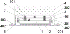
Computer CPU damping device
Technical Field
The utility model relates to a computer technology field, concretely relates to computer CPU damping device.
Background
At present, with the continuous development of computer applications, the applications of computers are more and more extensive, and for computers, the performance of the computers is crucial to the use of the computers. For some occasions, the computer needs to work in a severe environment, such as an oscillation environment, a bump environment and the like, which puts high requirements on the shock resistance of the computer, and especially for a CPU of the computer, the CPU is used as the brain of the computer, and the shock resistance of the CPU is important.
Many CPU heat sinks install radiator fan above the CPU motherboard, and when the computer is in an oscillating and bumpy environment, the CPU motherboard and the fan easily collide with each other, causing damage to the CPU motherboard and affecting the use of the computer.
Disclosure of Invention
For solving the problem that proposes among the above-mentioned background art, the utility model provides a computer CPU damping device has the characteristics that can prevent CPU mainboard and radiator fan collision each other.
In order to achieve the above object, the utility model provides a following technical scheme: the utility model provides a computer CPU damping device, includes the CPU body, the mounting groove is installed in the outside of CPU body, the equal fixed connection in the left and right sides of mounting groove is fluted, two the dead lever, two are all pegged graft to the inner wall of recess the upper end fixedly connected with apron of dead lever, a plurality of evenly distributed's louvre is seted up to the up end of apron, the fan is installed to the top of apron, the lower terminal surface fixed mounting of fan has a plurality of evenly distributed's a flexible section of thick bamboo, and is a plurality of the equal fixedly connected with first spring of inner wall of a flexible section of thick bamboo, and is a plurality of the lower extreme of first spring all with the up end swing joint of apron.
In order to place the CPU mainboard and the apron collision, as the utility model relates to a computer CPU damping device is preferred, the equal fixedly connected with second telescopic cylinder in the left and right sides of terminal surface under the apron, two the equal fixedly connected with second spring of the inner wall of the telescopic cylinder of second, two the lower extreme of second spring runs through the below that two second telescopic cylinders and extend to two second telescopic cylinders respectively, two the equal fixedly connected with of lower extreme of second spring separates the separation blade.
For the convenience of installation fan, as the utility model relates to a computer CPU damping device is preferred, the equal fixedly connected with backup pad in the left and right sides of the lower terminal surface of fan, two the equal fixedly connected with fixed plate in one side that the backup pad was carried on the back mutually, two the equal threaded connection of up end of fixed plate has the screw, two the lower extreme and the bottom plate of screw all run through connection.
In order to more stably support the fan, as the utility model relates to a computer CPU damping device is preferred, two the shape of backup pad all is the cambered surface form.
In order to avoid spring damage CPU mainboard, as the utility model relates to a computer CPU damping device is preferred, the material that separates the separation blade is rubber, the diameter that separates the separation blade is greater than the outer diameter of the flexible section of thick bamboo of second.
Compared with the prior art, the beneficial effects of the utility model are that:
1. this kind of computer CPU damping device, respectively with two recess joints through two dead levers, and then with the position fixing of apron in the top of mounting groove, can make the cold air blow in inside the mounting groove through the louvre when the fan rotates, and then make the air flow around the CPU mainboard in order to reach radiating effect, when the device is in the environment of vibration, keep off through the partition of apron and can avoid fan and CPU body collision, and through the support of a plurality of first springs, can avoid apron and recess to break away from, play buffering cushioning effect to the apron vibration simultaneously, thereby prevent that the CPU body from suffering collision damage.
2. This kind of computer CPU damping device, when the CPU body produced the vibration, the second spring compression drove the flexible section of thick bamboo of second and shortens, and the pressure that the second spring will receive this moment rebounds to the CPU body, and then reaches the shock attenuation effect to the CPU body.
3. This kind of computer CPU damping device, the fender piece texture that separates that rubber was made is softer, through separating terminal surface and CPU mainboard butt under the fender piece, and then can avoid the direct and CPU body contact of metal spring to cause the CPU mainboard to damage when the second spring is flexible.
Drawings
The accompanying drawings are included to provide a further understanding of the invention, and are incorporated in and constitute a part of this specification, illustrate embodiments of the invention, and together with the description serve to explain the invention and not to limit the invention. In the drawings:
FIG. 1 is a cross-sectional view of a computer CPU damping device of the present invention;
FIG. 2 is a structural diagram of a computer CPU damping device of the present invention;
fig. 3 is a schematic view of the position a of the present invention.
In the figure, 1, a CPU body; 2. mounting grooves; 201. a groove; 3. a cover plate; 301. fixing the rod; 302. heat dissipation holes; 4. a fan; 401. a support plate; 402. a fixing plate; 403. a screw; 5. a base plate; 6. a first telescopic cylinder; 601. a first spring; 7. a second telescopic cylinder; 701. a second spring; 702. separating and blocking piece.
Detailed Description
In order to make the objects, technical solutions and advantages of the present invention more clearly understood, the present invention is further described in detail below with reference to the accompanying drawings and embodiments. It should be understood that the specific embodiments described herein are merely illustrative of the invention and are not intended to limit the invention.
In the description of the present invention, it is to be understood that the terms "length", "width", "upper", "lower", "front", "rear", "left", "right", "vertical", "horizontal", "top", "bottom", "inner", "outer", and the like indicate orientations or positional relationships based on those shown in the drawings, and are merely for convenience of description and simplicity of description, and do not indicate or imply that the device or element being referred to must have a particular orientation, be constructed and operated in a particular orientation, and thus, should not be construed as limiting the present invention. In addition, in the description of the present invention, "a plurality" means two or more unless specifically limited otherwise.
Referring to fig. 1-3, the present invention provides the following technical solutions: the utility model provides a computer CPU damping device, including CPU body 1, mounting groove 2 is installed in CPU body 1's the outside, the equal fixedly connected with recess 201 in the left and right sides of mounting groove 2, dead lever 301 has all been pegged graft to the inner wall of two recess 201, the upper end fixedly connected with apron 3 of two dead levers 301, a plurality of evenly distributed's louvre 302 has been seted up to the up end of apron 3, fan 4 is installed to the top of apron 3, fan 4's lower terminal surface fixed mounting has a plurality of evenly distributed's first telescopic cylinder 6, the first spring 601 of the equal fixedly connected with of inner wall of a plurality of first telescopic cylinder 6, the lower extreme of a plurality of first springs 601 all with apron 3's up end swing joint.
In this embodiment: through two dead levers 301 respectively with two recess 201 joints, and then fix the position of apron 3 in the top of mounting groove 2, can make the cold air blow in inside mounting groove 2 through louvre 302 when fan 4 rotates, and then make the air flow around the CPU mainboard in order to reach radiating effect, when the device is in the environment of vibration, keep off through the partition of apron 3 and can avoid fan 4 and CPU body 1 collision, and through the support of a plurality of first springs 601, can avoid apron 3 and recess 201 to break away from, play buffering cushioning effect to apron 3 vibration simultaneously, thereby prevent that CPU body 1 from suffering collision damage.
As a technical optimization scheme of the utility model, the equal fixedly connected with second telescopic tube 7 in the left and right sides of terminal surface under the apron 3, the equal fixedly connected with second spring 701 of the inner wall of two second telescopic tubes 7, two second spring 701's lower extreme runs through two second telescopic tubes 7 respectively and extends to the below of two second telescopic tubes 7, and the equal fixedly connected with of lower extreme of two second springs 701 separates separation blade 702.
In this embodiment: when the CPU body 1 vibrates, the second spring 701 compresses and drives the second telescopic cylinder 7 to shorten, and at this time, the second spring 701 rebounds the pressure applied to the CPU body 1, thereby achieving a damping effect on the CPU body 1.
As a technical optimization scheme of the utility model, the equal fixedly connected with backup pad 401 in the left and right sides of the lower terminal surface of fan 4, two backup pads 401 back on the back the same body the equal fixedly connected with fixed plate 402 in one side, the equal threaded connection of up end of two fixed plates 402 has screw 403, the lower extreme and the bottom plate 5 of two screws 403 all through connection.
In this embodiment: through using screw 403 to run through fixed plate 402 and bottom plate 5, and then the position of fixed fan 4, when dismantling the CPU mainboard, screw 403 is unscrewed and fan 4 is dismantled, and then makes first spring 601 and apron 3 separate, does not have the pressure above the apron 3 and to upwards moving can take out two dead levers 301 to dismantle the inside CPU body 1 of mounting groove 2.
As a technical optimization scheme of the present invention, the shapes of the two supporting plates 401 are both arc-surface-shaped.
In this embodiment: the left side and the right side of the fan 4 are supported by the arc-shaped supporting plate 401, so that the contact area between the supporting plate 401 and the bottom plate 5 can be increased, and the position of the fan 4 is further stably fixed, so that the fan 4 is prevented from shaking all around.
As a technical optimization scheme of the utility model, the material that separates separation blade 702 is rubber, and the diameter that separates separation blade 702 is greater than the outer diameter of the flexible section of thick bamboo 7 of second.
In this embodiment: the fender piece 702 texture that separates that rubber was made is softer, through separating under the fender piece 702 terminal surface and CPU mainboard butt, and then can avoid metal spring direct and the contact of CPU body 1 to cause the CPU mainboard to damage when second spring 701 is flexible.
The utility model discloses a theory of operation and use flow: through two dead levers 301 respectively with two recess 201 joints, and then fix the position of apron 3 in the top of mounting groove 2, can make the cold air blow in inside mounting groove 2 through louvre 302 when fan 4 rotates, and then make the air flow around the CPU mainboard in order to reach radiating effect, when the device is in the environment of vibration, keep off through the partition of apron 3 and can avoid fan 4 and CPU body 1 collision, and through the support of a plurality of first springs 601, can avoid apron 3 and recess 201 to break away from, play buffering cushioning effect to the vibration of apron 3 simultaneously, thereby prevent CPU body 1 from suffering collision damage, when CPU body 1 produces the vibration, second spring 701 compression and drive second telescopic cylinder 7 shorten, the pressure that second spring 701 will receive this moment rebounds to CPU body 1, and then reach the shock attenuation effect to CPU body 1.
The above description is only exemplary of the present invention and should not be construed as limiting the present invention, and any modifications, equivalents and improvements made within the spirit and principles of the present invention are intended to be included within the scope of the present invention.