Magnetic suction type desk lamp
Technical Field
The utility model relates to a lighting apparatus technical field, concretely relates to formula desk lamp is inhaled to magnetism.
Background
The desk lamp is a common lighting appliance, is mostly used for indoor lighting, and is generally placed on a desk or beside a sofa for lighting or furnishing.
At present, most lamp bodies and supporting rods of table lamps in the market are integrated and not detachable, the functions are single, and inconvenience is brought to users in the aspects of moving or storing; the desk lamp with the detachable lamp body and the detachable support frame is complex in connection mode and inconvenient to mount and dismount, the mounting and dismounting functions of the detachable desk lamp are limited to packaging and transportation, the functions of the detachable desk lamp are limited to desktop illumination provided by the traditional desk lamp, and the application requirements of multi-scene illumination cannot be met, so that improvement is needed.
SUMMERY OF THE UTILITY MODEL
An object of the utility model is to prior art's defect and not enough, provide a formula desk lamp is inhaled to magnetism, have that the function is various, easy dismounting, rotatory nimble, simple structure, appearance advantage pleasing to the eye.
In order to achieve the above object, the utility model adopts the following technical scheme: a magnetic suction type desk lamp comprises: a lamp socket; the lamp body is assembled on the lamp holder in a quick-release manner and can be used as a movable light source for independent use; and the magnetic attraction component is arranged between the lamp holder and the lamp body, is used for realizing quick-release assembly between the lamp body and the lamp holder and adjusting the irradiation angle and range of the lamp body.
The subassembly is inhaled to magnetism includes: the first magnetic suction part is arranged on the lamp body; the second magnetic part is arranged on the lamp holder and is used for being attracted with the first magnetic part to fix the lamp body; the first magnetic part can move relative to the second magnetic part to adjust the irradiation angle and range of the lamp body.
The second magnetic part is a sphere or a hemisphere.
The first magnetic part corresponds to a groove formed in the second magnetic part, and the groove is used for partially wrapping the second magnetic part to increase the contact area with the second magnetic part and enable the lamp body to be assembled between the lamp holder more stably.
The lamp holder is spliced with a support, a containing groove is formed in the support, a jack is formed in the bottom of the containing groove, a supporting shaft is rotatably assembled in the jack, the other end of the supporting shaft is fixedly assembled with the second magnetic suction part, and the second magnetic suction part is accommodated in the containing groove.
The bracket is provided with a limiting ring which is used for being sleeved on the second magnetic suction part so as to limit the second magnetic suction part in the accommodating groove, thereby preventing the second magnetic suction part from separating from the bracket.
The limiting ring is provided with a plug connector, the bracket is provided with a slot corresponding to the plug connector, and the plug connector is used for being plugged with the slot so that the limiting ring is fixedly assembled on the bracket.
The lamp body includes: a housing; a power supply component disposed within the housing; a control assembly disposed within the housing and electrically connected to the power assembly; and the light source component is rotatably assembled at one end of the shell and is electrically connected with the control component.
The shell sets up to be the V type, first magnetism portion of inhaling set up in the pointed end of shell.
After the technical scheme is adopted, the utility model discloses beneficial effect does:
1. through setting up first magnetism portion of inhaling on the lamp body and setting up the second magnetism portion of inhaling on the lamp stand for the magnetism through passing between lamp body and the lamp stand is inhaled the mode and is connected, not only makes things convenient for the dismantlement between lamp body and the lamp stand, dismantles the lamp body moreover, can be used as portable light source such as flashlight, wall lamp and use, has improved the practicality of desk lamp, thereby satisfies people's multiple demand.
2. Through setting up the support on the lamp stand, and be equipped with the storage tank on the support, tank bottom rotary type at the storage tank is equipped with the pivot, the other end of pivot is fixed with the second magnetism and inhales the portion, the second magnetism is inhaled partial volume and is arranged in the storage tank, and the cover is equipped with the spacing ring on outstanding part, spacing ring fixed mounting is on the support, with this, through shifting the lamp body from top to bottom or from left to right, alright make the first magnetism inhale the piece and can inhale the portion and rotate on the second magnetism, thereby adjust the angle of illumination and the scope of light source subassembly.
3. The contact surface through inhaling portion and second magnetism and inhale the portion sets complementary unsmooth sphere into with first magnetism, has increased the area of contact between first magnetism portion of inhaling and the second magnetism portion of inhaling to make the assembly between lamp body and the lamp stand more stable, have that the function is various, easy dismounting, rotatory nimble, simple structure, appearance advantage pleasing to the eye.
Drawings
In order to more clearly illustrate the embodiments of the present invention or the technical solutions in the prior art, the drawings needed to be used in the description of the embodiments or the prior art will be briefly described below, it is obvious that the drawings in the following description are only some embodiments of the present invention, and for those skilled in the art, other drawings can be obtained according to these drawings without inventive exercise.
Fig. 1 is a schematic structural view of the lamp socket and the lamp body of the present invention in a separated state;
fig. 2 is a half sectional view of the present invention;
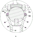
FIG. 3 is an enlarged view corresponding to detail A in FIG. 2;
FIG. 4 is an enlarged view corresponding to detail B in FIG. 2;
FIG. 5 is an enlarged view corresponding to detail C in FIG. 2;
fig. 6 is a schematic view of the lamp body according to the present invention during the adjustment of the irradiation angle;
fig. 7 is a schematic view of the lamp body according to the present invention during irradiation range adjustment;
fig. 8 is a schematic structural view of the housing and the hidden light source assembly with a rotating shaft structure according to the present invention;
FIG. 9 is an enlarged view corresponding to detail D in FIG. 8;
fig. 10 is a schematic view of the overall structure of the present invention;
fig. 11 is a schematic view of the lamp body of the present invention as a wall lamp.
Description of reference numerals: 1. a lamp socket; 11. a base; 12. a support bar; 2. a lamp body; 21. a housing; 211. An upper shell; 212. a hook portion; 213. a peripheral portion; 214. a lower case; 215. a side cover; 216. a stopper; 22. a power supply component; 221. a storage battery; 222. a charging port; 23. a control component; 231. a control button; 232. a circuit board; 233. a warning light; 24. a light source assembly; 3. a magnetic component; 31. a first magnetic attraction part; 311. a groove; 32. a second magnetic attraction part; 33. a support; 331. a containing groove; 332. a limiting ring; 34. a support shaft; 4. a hidden rotating shaft structure; 41. a rotating shaft; 42. the rotating shaft is pressed; 43. a limiting block; 44. a stopper block; 45. a bump; 46. a fixed part; 47. an assembly hole; 48. a fastener.
Detailed Description
The present invention will be described in further detail with reference to the accompanying drawings.
The present embodiment is only for explaining the present invention, and it is not limited to the present invention, and those skilled in the art can make modifications to the present embodiment as required without making a contribution, but all the embodiments are protected by the patent law within the scope of the claims of the present invention.
This embodiment relates to a formula desk lamp is inhaled to magnetism, as shown in fig. 1, 2, include: lamp stand 1, lamp body 2 and magnetism subassembly 3 of inhaling. The lamp holder 1 comprises a base 11 and a support rod 12 inserted on the base 11. The lamp body 2 quick detach formula assemble in on the bracing piece 12, the lamp body 2 of dismantling can be used as the removal light source and use, can also hang and locate to do the wall lamp and use, can satisfy people daily life's multiple demand, realizes the multi-functionalization of desk lamp simultaneously. Magnetism inhale subassembly 3 some set up in on the bracing piece 12, another part sets up on lamp body 2, and magnetism inhale subassembly 3 and be used for realizing lamp body 2 with quick detach formula assembly between the bracing piece 12, lamp body 2 uses magnetism to inhale subassembly 3 and carries out luffing motion or rotation as the strong point to adjust and bracing piece 12 between contained angle, or the angle modulation of base 11 relatively, thereby realize lamp body 2's the regulation of angle of illumination and scope.
As shown in fig. 2 and 3, the magnetic attraction component 3 includes: a first magnetic part 31 and a second magnetic part 32.
The first magnetic part 31 is fixedly assembled on the lamp body 2, the second magnetic part 32 is assembled on the lamp holder 1, and the second magnetic part 32 is used for being attracted with the first magnetic part 31 to fix the lamp body 2. Preferably, the second magnetic portion 32 is a sphere made of magnetic metal, the first magnetic portion 31 is a magnet, and the second magnetic portion 32 can also be a hemisphere or a sphere larger than 1/2 and smaller than 1.
In order to increase the contact area between the first magnetic attraction part 31 and the second magnetic attraction part 32, the lamp body 2 and the support frame are assembled more stably. The first magnetic part 31 corresponds to the groove 311 of the second magnetic part 32, and the groove 311 can partially cover the second magnetic part 32. In order to make the appearance of the lamp body 2 more beautiful, a through hole is formed in the housing 21 of the lamp body 2 corresponding to the first magnetic absorption portion 31, and the first magnetic absorption portion 31 is fixedly assembled in the housing 21 corresponding to the through hole. And a peripheral portion 213 is disposed on the housing 21 around the edge of the through hole, and when the first magnetic portion 31 is attracted to the second magnetic portion 32, the second magnetic portion 32 is partially covered by the peripheral portion 213 and the recess 311.
As shown in fig. 2 and 4, a support 33 for fixing the second magnetic attraction part 32 is disposed at one end of the support frame away from the base 11, one end of the support 33 is inserted into the support frame, the other end of the support 33 is disposed with a receiving groove 331, a receptacle is disposed at the bottom of the receiving groove 331, a support shaft 34 is rotatably assembled in the receptacle, the other end of the support shaft 34 is fixedly assembled with the second magnetic attraction part 32, and a part of the second magnetic attraction part 32 is received in the receiving groove 331. Preferably, the second magnetic part 32 is provided with a threaded hole corresponding to the supporting shaft 34, the supporting shaft 34 is provided with an external thread, and the supporting shaft 34 is connected with the second magnetic part 32 by a thread. In order to prevent the second magnetic portion 32 from separating from the bracket 33, or when the lamp body 2 is dismounted, the second magnetic portion 32 is taken away together with the bracket 33, a limiting ring 332 is detachably assembled at the end of the bracket 33, the limiting ring 332 is sleeved on the second magnetic portion 32 to limit the second magnetic portion 32 in the accommodating groove 331, and the limiting ring 332 can also be replaced by a plurality of pressing blocks. Further, be provided with the plug connector on the spacing ring 332, correspond on the support 33 the plug connector is provided with the slot, the plug connector be used for with the slot grafting, so that the spacing ring 332 fixed assembly in on the support 33.
When the lamp body 2 is manually operated to swing in the longitudinal direction, the first magnetic attraction part 31 rotates around the center of the sphere on the second magnetic attraction part 32 to adjust the included angle between the lamp body 2 and the support frame, so that the lamp body 2 is raised or lowered to adjust the irradiation range, in this embodiment, the included angle range of the swing of the lamp body 2 is within 40 degrees, and in other embodiments, the included angle range of the swing of the lamp body 2 is within 30, 50 or 60 degrees. When the lamp body 2 is rotated in the horizontal direction by manual operation, the first magnetic attraction part 31 and the second magnetic attraction part 32 rotate around the axis of the supporting shaft 34, so as to adjust the irradiation angle of the lamp body 2, and the rotatable range of the lamp body 2 is 360 degrees.
As shown in fig. 2, the lamp body 2 includes: a casing 21, a power supply assembly 22, a control assembly 23, a light source assembly 24 and a hidden rotary shaft 41 structure 4. The housing 21 includes an upper housing 211, a lower housing 214, and a side cover 215, a hook portion 212 is disposed on an inner wall of the lower housing 214, and the hook portion 212 is used for hooking an inner wall of the upper housing 211, so that the upper housing 211 and the lower housing 214 are covered with each other. The lower shell 214 is provided with a hook part 212, and the lower shell 214 is clamped with the inner wall of the upper shell 211 through the hook part 212. The power supply unit 22 is provided in the housing 21, and the power supply unit 22 includes a battery 221 and a charging port 222 provided in the side cover 215. The control assembly 23 is disposed in the housing 21, the control assembly 23 includes a control button 231, a circuit board 232 and a warning light 233, and the circuit board 232 is electrically connected to the power supply assembly 22, the light source assembly 24, the control button 231 and the warning light 233 through wires, and is used for controlling the illumination brightness and the on-off of the light source assembly 24. The light source assembly 24 is rotatably assembled at one end of the housing 21, and the hidden rotating shaft 41 structure 4 is assembled between the housing 21 and the light source assembly 24, and is used for realizing the rotatable assembly between the two.
As shown in fig. 8 and 9, the hidden type rotating shaft 41 structure 4 includes: a rotating shaft 41, a rotating shaft pressing block 42 and a limiting block 43.
One end of the rotating shaft 41 is fixedly assembled on the lamp source assembly, and the other end is rotatably assembled in the housing 21. The rotating shaft pressing block 42 is pressed on the rotating shaft 41 and detachably assembled on the inner wall of the lower shell 214. In order to prevent the rotating shaft 41 from moving axially away from the housing 21, which may cause the lamp source assembly to break, a limiting block 43 is disposed on the rotating shaft 41, and the limiting block 43 is used to cooperate with a stop 216 on the inner wall of the upper housing 211 to limit the rotating shaft 41 in the housing 21. Preferably, the stopper 43 is annular and is integrally formed with the rotation shaft 41. The desk lamp is high in integrity and attractive in appearance by means of the built-in rotating shaft 41.
In order to prevent the connecting wires between the light source assembly 24 and the control device from being twisted or twisted off due to multiple rotations during use, the spindle pressing block 42 is provided with a stop block 44, the spindle 41 is provided with a projection 45 corresponding to the stop block 44, and when the power supply assembly 22 rotates around the axis, the stop block 44 and the projection 45 are matched for use to limit the angle of rotation of the spindle 41 along the axis. Preferably, the pressing surface of the rotating shaft pressing block 42 is a cambered surface. The stop block 44 is formed by extending a part of the spindle pressing piece 42 in the axial direction.
As shown in fig. 9, the rotating shaft pressing block 42 is further provided with a fixing portion 46, the fixing portion 46 is provided with an assembling hole 47, and the assembling hole 47 is used for a fastening member 48 to assemble and fix the rotating shaft pressing block 42 on the inner wall of the lamp housing or the lamp holder 1.
The working principle of the utility model is as follows: during the use, click switch in order to turn on the lamp, when adjusting the irradiation range, handheld lamp body 2 arbitrary position makes it to keeping away from or being close to the direction swing of lamp stand 1, and at this moment, first magnetism portion 31 is in rotate around its centre of sphere on second magnetism portion 32 to fix under the effect of magnetic force on the angle of presetting, with through changing the contained angle between lamp body 2 and the bracing piece 12, realize desk lamp irradiation range's regulation. When the irradiation angle is adjusted, the user holds any part of the lamp body 2 to rotate the first magnetic part, the second magnetic part 32 and the support shaft 34 around the axis simultaneously, so as to adjust the irradiation angle of the desk lamp.
When the lamp body 2 is used as a movable light source, the lamp holder 1 and the lamp body 2 are respectively held by two hands to move in opposite directions, so that the lamp body 2 is separated from the lamp holder 1, and the lamp body 2 can be carried about as a movable light source or fixed on a wall, a bedstead or other places needing illumination through a support 33 or a magnetic attraction mode.
The above description is only for the purpose of illustration and not limitation, and other modifications or equivalent replacements made by those skilled in the art to the technical solution of the present invention should be covered by the scope of the claims of the present invention as long as they do not depart from the spirit and scope of the technical solution of the present invention.