CN212495729U - Aluminum template sawing machine convenient to location - Google Patents
Aluminum template sawing machine convenient to location Download PDFInfo
- Publication number
- CN212495729U CN212495729U CN202021303685.4U CN202021303685U CN212495729U CN 212495729 U CN212495729 U CN 212495729U CN 202021303685 U CN202021303685 U CN 202021303685U CN 212495729 U CN212495729 U CN 212495729U
- Authority
- CN
- China
- Prior art keywords
- workstation
- sawing machine
- fixed block
- fixed
- machine convenient
- Prior art date
- Legal status (The legal status is an assumption and is not a legal conclusion. Google has not performed a legal analysis and makes no representation as to the accuracy of the status listed.)
- Active
Links
Images


Abstract
The utility model relates to an aluminium template sawing machine convenient to location, including the workstation, the workstation below is provided with the annular saw, is provided with on the workstation and supplies the annular saw to stretch out the cutting groove on workstation surface, is provided with the fixed block on the workstation, and the raw materials spare is contradicted in one side of fixed block, and the fixed block upper surface is provided with the scale, and fixed block one end still is provided with the setting element, and raw materials spare tip supports on the setting element. This application has the effect of the length of convenient accurate cutting raw materials spare.
Description
Technical Field
The application relates to the field of aluminum template processing equipment, in particular to an aluminum template sawing machine convenient to locate.
Background
The aluminum formwork is a new generation formwork system, is a universal accessory consisting of an aluminum panel, a support and a connecting piece, can be combined and spliced into an integral formwork with different sizes and complex overall dimensions, overcomes the defects of the traditional formwork in the past, and greatly improves the construction efficiency. Before the aluminum template is formed, the raw material plates need to be cut into different sizes, and the aluminum template is convenient to process and assemble.
There is the correlation technique to disclose an aluminum mould board sawing machine at present, including the workstation, the below of workstation is provided with the circular saw machine, sets up the cutting groove that supplies the circular saw to pass through on the workstation, is equipped with the drive arrangement of drive circular saw machine horizontal migration on the workstation. A fixed block is arranged on the workbench, and an air cylinder is fixed on the fixed block and vertically arranged. And after the length of the raw material piece to be cut is determined, controlling the air cylinder to enable the air cylinder to compress the raw material piece.
In view of the above-mentioned related art, the inventors have considered that there is a drawback that it is not convenient to accurately determine the cut length of the raw material piece.
SUMMERY OF THE UTILITY MODEL
In order to conveniently and accurately cut the length of a raw material piece, the application provides an aluminum template sawing machine convenient to locate.
The application provides a pair of aluminum mould board sawing machine convenient to location adopts following technical scheme:
the utility model provides an aluminium template sawing machine convenient to location, includes the workstation, and the workstation below is provided with the annular saw, is provided with on the workstation and supplies the annular saw to stretch out the cutting groove on workstation surface, is provided with the fixed block on the workstation, and the raw materials spare is contradicted in one side of fixed block, and the fixed block upper surface is provided with the scale, and fixed block one end still is provided with the setting element, and raw materials spare tip supports on the setting element.
Through adopting above-mentioned technical scheme, can confirm the length of raw materials piece cutting according to the scale, support raw materials piece on the setting element, prevent that when the cutting, raw materials piece slides on the workstation for cutting accuracy is more accurate.
Preferably, the locating piece is including supporting the fixed knot on the fixed block tightly, fixed knot with place the raw materials spare lateral wall on the homonymy be connected with the locating plate, raw materials spare tip supports at the locating plate edge.
Through adopting above-mentioned technical scheme, the locating plate makes the fixed knot avoid compressing tightly the cylinder to stretch into fixed block one side, make its length scope grow that can be spacing.
Preferably, the fixed button lateral wall is fixed with the nut, and the fixed button lateral wall is last to have a hole at nut central authorities, and the nut (female connection has the regulation pole, adjusts the pole and passes the hole and support tightly on the fixed block.
By adopting the technical scheme, after the limiting position is determined, the screwing rod is screwed, so that the position of the fixing buckle is fixed, and the operation is convenient.
Preferably, one end of the positioning plate, which is far away from the fixing buckle, is provided with a bending plate, a slot is formed between the bending plate and the side wall of the fixing block, and the side wall of the raw material piece is inserted into the slot.
Through adopting above-mentioned technical scheme, make the raw materials spare more stable when fixed, prevent raw materials spare edge from locating plate one side slippage.
Preferably, the width of the slot is the same as the thickness of the side wall of the raw material piece.
Through adopting above-mentioned technical scheme, make raw materials spare more stable by spacing in the slot, support tight fixed block and slot, make raw materials spare more stable.
Preferably, a screw rod is arranged at one end of the fixing block and is in threaded connection with the workbench.
Through adopting above-mentioned technical scheme, the screw rod is screwed off, the contained angle between fixed block adjustment and the cutting groove, behind the set screw, consequently support the raw materials spare slope of tight on one side of the fixed block and place in cutting groove top, the angle that the raw materials spare was downcut promptly can be adjusted.
Preferably, the workbench is provided with an angle ruler, the angle ruler is superposed with the axis of the screw, and the zero scale mark of the angle ruler is parallel to the extending direction of the cutting groove.
Through adopting above-mentioned technical scheme, the angle square is convenient when rotating the fixed block and is monitored fixed block pivoted angle, convenient and practical and regulation.
Preferably, the circular saw sets up on the circular saw bed, sets up the slide rail along the extension of cutting groove length extending direction in the workstation below, and it has the sliding plate to slide on the slide rail, and the sliding plate bottom surface is fixed with vertical lifting cylinder, and lifting cylinder's output stretches out from the sliding plate and fixed with circular saw bed bottom surface, is provided with the pulling cylinder parallel with slide rail extending direction on the workstation of slide rail one end, and the output of pulling cylinder is fixed with the sliding plate.
Through adopting above-mentioned technical scheme, when needing to cut raw materials spare, pulling cylinder pulling circular sawing machine slides along cutting cut groove to lift the cylinder and lift up the circular sawing machine, the edge of circular saw stretches out from cutting cut groove promptly, cuts convenient operation to raw materials spare.
In summary, the present application includes at least one of the following beneficial technical effects:
1. the cutting length of the raw material piece can be determined by referring to the graduated scale, the raw material piece is abutted against the positioning piece, and the raw material piece is prevented from sliding on the workbench during cutting, so that the cutting precision is more accurate;
2. the raw material part is more stably limited in the slot and tightly abuts against the fixing block and the slot, so that the raw material part is more stable.
Drawings
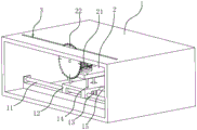
FIG. 1 is a schematic view of the overall structure of embodiment 1 of the present application;
FIG. 2 is a schematic structural view of a circular sawing machine sliding on a worktable in embodiment 1 of the present application;
FIG. 3 is a schematic view of the position structure of the pulling cylinder and the circular saw bed in embodiment 1 of the present application;
FIG. 4 is a schematic structural view of a squeeze cylinder in embodiment 1 of the present application;
FIG. 5 is a schematic view of the structure of the material piece abutting on the positioning plate in embodiment 1 of the present application;
FIG. 6 is an enlarged partial schematic view of portion A of FIG. 1;
FIG. 7 is a schematic view of a structure in which a blank is inserted into a socket in example 2 of the present application;
fig. 8 is a schematic structural view of the angle ruler in embodiment 2 of the present application.
Description of reference numerals: 1. a work table; 11. a slide rail; 12. a sliding plate; 13. a lifting cylinder; 14. a positioning column; 15. pulling the cylinder; 2. a circular saw bed; 21. a motor; 22. a circular saw; 3. cutting the groove; 4. a fixed block; 41. a screw; 5. a pressing cylinder; 6. a raw material piece; 7. a positioning member; 71. a fixing buckle; 72. a nut; 73. screwing the rod; 74. pulling a rod; 75. positioning a plate; 8. a graduated scale; 9. a column; 91. an adjustment member; 911. a through hole; 912. fastening a bolt; 92. adjusting a rod; 10. a slot; 101. a bending plate; 16. an angle ruler.
Detailed Description
The present application is described in further detail below with reference to the attached drawings.
The embodiment of the application discloses aluminum mould board sawing machine convenient to location.
Example 1
Referring to fig. 1 and 2, the aluminum formwork sawing machine includes a worktable 1, a circular sawing machine 2 is disposed below the worktable 1, a motor 21 is fixed on the circular sawing machine 2, and the motor 21 drives a circular saw 22 to rotate. A cutting groove 3 is provided on the table 1, through which a circular saw 22 protrudes. Be provided with fixed block 4 at 1 upper surface of workstation, raw materials part 6 pastes tight fixed block 4 during the cutting to raw materials part 6 is located the top of cutting groove 3, is fixed with scale 8 on fixed block 4, conveniently observes scale 8 and leaves the length of getting cutting back raw materials part 6.
Referring to fig. 2 and 3, a slide rail 11 is provided below the table 1, the circular saw bed 2 is fixed on a slide plate 12, the slide plate 12 slides on the slide rail 11, a vertical lifting cylinder 13 is fixed on the bottom surface of the slide plate 12, the output end of the lifting cylinder 13 extends out of the slide plate 12 and is fixed with the bottom surface of the circular saw bed 2, and a positioning column 14 slidably connected with the slide plate 12 is fixed on the bottom surface of the circular saw bed 2. A pulling cylinder 15 parallel to the extension direction of the slide rail 11 is arranged on the workbench 1 at one end of the slide rail 11, and the output end of the pulling cylinder 15 is fixed with the sliding plate 12. The cutting groove 3 is located right above the circular saw 22, and the extending direction of the cutting groove 3 is the same as the sliding direction of the circular saw 22.
When cutting, the pulling cylinder 15 pulls the circular saw bed 2 to slide along the slide rail 11, and the lifting cylinder 13 pushes the circular saw bed 2 to rise, so that the circular saw 22 protrudes from the cutting groove 3 and travels along the cutting groove 3, and the motor 21 drives the circular saw 22 to rotate, so that the material piece 6 placed above the cutting groove 3 is cut.
Referring to fig. 4, a screw 41 vertically penetrates through one end of the fixing block 4, a threaded hole is formed in the table 1, and the screw 41 is inserted into the threaded hole and screwed, so that the fixing block 4 can be fixed on the table 1. An included angle is formed between the edge of one side of the fixing block 4 and the cutting groove 3, when the included angle between the fixing block 4 and the cutting groove 3 needs to be adjusted, the screw rod 41 is unscrewed, the fixing block 4 is rotated, and the screw rod 41 is screwed again, so that the angle between the raw material part 6 and the cutting groove 3 is changed, and the raw material part 6 is cut according to requirements. Referring to fig. 1, a material piece 6 is placed on a table 1, and one side wall of the material piece abuts against a fixing block 4, the material piece 6 is obliquely placed on a cutting groove 3, and after a circular saw 22 (see fig. 2) passes through the cutting groove 3, one end of the material piece 6 is cut into an inclined surface.
Referring to fig. 4, in order to fix the raw material piece 6 in a vertical direction, two sets of pressing cylinders 5 are provided on the fixing block 4. Two vertical upright posts 9 are fixed on the top surface of the fixed block 4, an adjusting piece 91 is arranged on each upright post 9, two through holes 911 with vertical axes are formed in each adjusting piece 91, openings communicated with the side wall of the fixed block 4 are formed in two sides of each through hole 911, and fastening bolts 912 are fixed on the openings. The upright post 9 penetrates into one through hole 911 and can slide relatively, the fastening bolt 912 is screwed, and the height of the adjusting piece 91 is fixed; the compressing cylinder 5 is fixed on a screwing rod 73, the screwing rod 73 is inserted into another through hole 911 of the adjusting piece 91 and is fixed, so that the position of the compressing cylinder 5 above the raw material piece 6 can be adjusted, and the position for better compressing the raw material piece 6 can be found conveniently.
Referring to fig. 5, in order to determine the length of the cut material piece 6, a positioning member 7 is provided at one end of the fixing block 4. The setting element 7 is including sunken into the fixed knot 71 of trough-shaped, and fixed knot 71 from top to bottom blocks the fixed block 4 outside, refer to fig. 1 and 6, is fixed with the nut 72 on fixed knot 71 one side lateral wall, has the hole of seting up at nut 72 central authorities on the fixed knot 71 lateral wall, and nut 72 threaded connection has the pole 73 of screwing, and the pole 73 one end of screwing sets up the lever 74 of pulling, conveniently rotates the regulation pole 73, makes the pole 73 of screwing pass the hole and support the fixed block 4.
Referring to fig. 5, the fixing buckle 71 is connected to a positioning plate 75 closely attached to a side wall of the fixing block 4. The zero scale mark of the graduated scale 8 is positioned on one side edge of the fixed block 4 close to the cutting groove 3, one corner of the fixed block 4 is attached to the cutting groove 3, and the edge of the positioning plate 75 close to one end of the cutting groove 3 corresponds to a certain scale on the graduated scale 8. After the raw material piece 6 is placed on the workbench 1 and the side wall of the raw material piece abuts against the side wall of the fixed block 4, the edge of the bottom end of the raw material piece 6 abuts against the edge of the positioning plate 75, the part of the raw material piece 6, which crosses the cutting groove 3, is cut off, namely, the distance between one end of the fixed block 4, which is close to the cutting groove 3, and the positioning plate 75 is the length of the cut raw material piece 6.
Therefore, the position of the fixing buckle 71 can be adjusted, and the scale of the graduated scale 8 corresponding to the edge of the positioning plate 75 can be observed, so that the length of the reserved raw material piece 6 can be determined.
The implementation principle of the embodiment 1 is as follows: and loosening the screw rod 41, rotating the fixed block 4, determining an included angle between the edge of the fixed block 4 and the cutting groove 3, and then screwing the screw rod 41.
According to the length of the raw material piece 6 to be obtained, the position of the fixing buckle 71 is adjusted to enable the edge of the positioning plate 75 to point to the scale corresponding to the length of the raw material piece 6 to be obtained, the pulling rod 74 is pulled, the screwing rod 73 is screwed, and the fixing buckle 71 and the positioning plate 75 are fixed.
The motor 21 and the pulling cylinder 15 are activated and the lifting cylinder 13 is raised, the rotating circular saw 22 is extended from the cutting groove 3 and slid along the cutting groove 3, and the piece of material 6 is cut.
Example 2
Referring to fig. 7 and 8, the difference from embodiment 1 is that since the edge of the positioning plate 75 is thin, when the material piece 6 abuts against the edge of the positioning plate 75, it is unstable, so that a slot 10 is provided at an edge of the positioning plate 75 far from the fixing buckle 71, the slot 10 is defined by a bending plate 101 connected to the edge of the positioning plate 75 and the positioning plate 75, and a gap between the bending plate 101 and the fixing block 4 is provided for the material piece 6 to insert. The width of the slot 10 is the same as the thickness of the side wall of the material piece 6, further stabilizing the material piece 6.
Still be provided with bevel protractor 16 on workstation 1, the centre of a circle of bevel protractor 16 and screw 41 axle center coincidence, the zero scale mark of bevel protractor 16 is parallel with cutting groove 3 extending direction, consequently when adjusting the raw materials piece 6 angle of cutting, convenient observation adjusts fixed block 4 according to the bevel protractor 16 sign.
The implementation principle of the embodiment 2 is as follows: and adjusting the angle of the fixed block 4 according to the mark of the angle ruler 16 to determine the cutting angle of the raw material part 6. When cutting the raw material piece 6, the raw material piece 6 is placed on the workbench 1, the side wall of one side of the raw material piece abuts against the fixing block 4, and the raw material piece slides along the side wall of the fixing block 4 in the slot 10 in opposite directions, so that the side wall of the raw material piece 6 is inserted into the slot 10.
The above embodiments are preferred embodiments of the present application, and the protection scope of the present application is not limited by the above embodiments, so: all equivalent changes made according to the structure, shape and principle of the present application shall be covered by the protection scope of the present application.
Claims (8)
1. The utility model provides an aluminum mould board sawing machine convenient to location, includes workstation (1), workstation (1) below is provided with circular saw (22), is provided with on workstation (1) and supplies circular saw (22) to stretch out cutting groove (3) on workstation (1) surface, is provided with fixed block (4) on workstation (1), and conflict in one side of fixed block (4), its characterized in that in raw materials spare (6): the upper surface of the fixed block (4) is provided with a graduated scale (8), one end of the fixed block (4) is also provided with a positioning part (7), and the end part of the raw material part (6) is abutted against the positioning part (7).
2. The aluminum template sawing machine convenient to position according to claim 1, wherein: the positioning piece (7) comprises a fixing buckle (71) which is abutted against the fixing block (4), the fixing buckle (71) and the side wall on which the raw material piece (6) is placed on the same side are connected with a positioning plate (75), and the end part of the raw material piece (6) is abutted against the edge of the positioning plate (75).
3. The aluminum template sawing machine convenient for positioning as recited in claim 2, wherein: be fixed with nut (72) on fixed knot (71) lateral wall, have the hole at nut (72) central authorities on fixed knot (71) lateral wall, nut (72) internal thread connection has regulation pole (73), adjusts pole (73) and passes the hole and support tightly on fixed block (4).
4. The aluminum template sawing machine convenient for positioning as recited in claim 2, wherein: one end, far away from the fixing buckle (71), of the positioning plate (75) is provided with a bending plate (101), a slot (10) is formed between the bending plate (101) and the side wall of the fixing block (4), and the side wall of the raw material piece (6) is inserted into the slot (10).
5. The aluminum template sawing machine convenient to position according to claim 4, wherein: the width of the slot (10) is the same as the thickness of the side wall of the raw material piece (6).
6. The aluminum template sawing machine convenient to position according to claim 1, wherein: and one end of the fixed block (4) is provided with a screw rod (41), and the screw rod (41) is in threaded connection with the workbench (1).
7. The aluminum template sawing machine convenient to position according to claim 6, wherein: an angle ruler (16) is arranged on the workbench (1), the angle ruler (16) is overlapped with the axis of the screw rod (41), and the zero scale mark of the angle ruler (16) is parallel to the extension direction of the cutting groove (3).
8. The aluminum template sawing machine convenient to position according to claim 1, wherein: circular saw (22) set up on circular saw bed (2), set up slide rail (11) along cutting groove (3) length extending direction extension in workstation (1) below, it has sliding plate (12) to slide on slide rail (11), sliding plate (12) bottom surface is fixed with vertical lifting cylinder (13), lifting cylinder's (13) output stretches out and is fixed with circular saw bed (2) bottom surface from sliding plate (12), be provided with pulling cylinder (15) parallel with slide rail (11) extending direction on workstation (1) of slide rail (11) one end, the output and sliding plate (12) of pulling cylinder (15) are fixed.
Priority Applications (1)
| Application Number | Priority Date | Filing Date | Title |
|---|---|---|---|
| CN202021303685.4U CN212495729U (en) | 2020-07-06 | 2020-07-06 | Aluminum template sawing machine convenient to location |
Applications Claiming Priority (1)
| Application Number | Priority Date | Filing Date | Title |
|---|---|---|---|
| CN202021303685.4U CN212495729U (en) | 2020-07-06 | 2020-07-06 | Aluminum template sawing machine convenient to location |
Publications (1)
| Publication Number | Publication Date |
|---|---|
| CN212495729U true CN212495729U (en) | 2021-02-09 |
Family
ID=74434155
Family Applications (1)
| Application Number | Title | Priority Date | Filing Date |
|---|---|---|---|
| CN202021303685.4U Active CN212495729U (en) | 2020-07-06 | 2020-07-06 | Aluminum template sawing machine convenient to location |
Country Status (1)
| Country | Link |
|---|---|
| CN (1) | CN212495729U (en) |
-
2020
- 2020-07-06 CN CN202021303685.4U patent/CN212495729U/en active Active
Similar Documents
| Publication | Publication Date | Title |
|---|---|---|
| CN208976550U (en) | A kind of aluminum alloy plate materials apparatus for bending | |
| CN212495729U (en) | Aluminum template sawing machine convenient to location | |
| CN101829913A (en) | Quick and accurate installing device of turning tool and installation method thereof | |
| CN201807905U (en) | Device for quickly and accurately assembling turning tools | |
| CN210413574U (en) | Machining clamp for radial drilling machine | |
| CN216097655U (en) | Cutting device for construction | |
| CN215392805U (en) | Positioning device of cutting machine | |
| CN115026580B (en) | Door frame clamping device capable of automatically adjusting upper-mounted datum plane | |
| CN219902480U (en) | Wood straight edge machine | |
| CN218903797U (en) | Adjustable clamping device for aluminum template machining | |
| CN220534281U (en) | Portable slitting jig of laminating machine | |
| CN220740239U (en) | Positioning and clamping tool for machining distributor bracket | |
| CN210100274U (en) | Fixing die capable of adjusting steel bar spacing | |
| CN219336179U (en) | Bevel connection cutting tool of aluminum alloy bracket for baby carrier | |
| CN216326765U (en) | Simple CNC clamping tool | |
| CN219404627U (en) | Quick centering positioning milling machine auxiliary fixture | |
| CN215149572U (en) | Ultra-large-diameter PE solid-wall pipe cutting equipment | |
| CN219005399U (en) | Cutting device is used in machining of machine parts | |
| CN211915578U (en) | Drilling machine convenient for drilling | |
| CN218080840U (en) | Wire cutting machine for PE (polyethylene) foaming plate | |
| CN220479905U (en) | Semitrailer saddle opening end cover side cut mould | |
| CN212885445U (en) | Copper bar cutting support capable of flexibly adjusting angle | |
| CN212528039U (en) | Plate cutting equipment | |
| CN213317974U (en) | Quick positioning plate shearing machine | |
| CN211360827U (en) | Cutting device is used in processing of reinforcement steel sheet |
Legal Events
| Date | Code | Title | Description |
|---|---|---|---|
| GR01 | Patent grant | ||
| GR01 | Patent grant |