Corrosion-resistant centrifugal pump
Technical Field
The utility model relates to a technical field of centrifugal pump specifically is a corrosion-resistant centrifugal pump.
Background
The centrifugal pump is in various forms of vertical type, horizontal type, single stage, multi-stage, single suction, double suction, self suction and the like, the centrifugal pump works by utilizing the rotation of an impeller to enable water to generate centrifugal motion, before the water pump is started, a pump shell and a water suction pipe are required to be filled with water, then a motor is started, a pump shaft drives the impeller and the water to generate high-speed rotation motion, the water generates centrifugal motion and is thrown to the outer edge of the impeller and flows into a water pressing pipeline of the water pump through a flow channel of a volute-shaped pump shell, the centrifugal motion is actually the expression of inertia of an object, such as water drops on an umbrella, when the umbrella rotates slowly, the water drops can rotate along with the umbrella because the friction force between the umbrella and the water drops is the centripetal force for supplying the water drops, but if the rotation of the umbrella is accelerated, the friction force is not enough to enable the water drops to do circular motion, the water drops can separate from the water drops to move towards the, if the speed is too high, the rope will break and the stone will fly out, which is called centrifugation.
At present, in the use process of the centrifugal pump, as solid particles may be mixed in water flow, the particles impact the impeller after entering the inside of the pump body, the service life of the impeller is seriously influenced, and if the quantity of the solid particles is too much, frequent cleaning of the inside of the pump body is possibly caused, so that the working efficiency of the pump body is reduced.
Disclosure of Invention
Technical problem to be solved
Not enough to prior art, the utility model provides a corrosion-resistant centrifugal pump possesses the filter effect and good and advantage such as be convenient for clean, has solved the problem that the granule rubbish in the rivers led to the fact irreversible injury to the impeller.
(II) technical scheme
In order to achieve the above purpose, the utility model discloses a following technical scheme realizes: a corrosion-resistant centrifugal pump comprises a pump body, wherein a first water inlet is formed in one side of the pump body, a filter box is arranged at the first water inlet, an overflow groove is formed in the filter box, a connecting port is formed in one side, close to the first water inlet, of the filter box, a second water inlet is formed in the top of the filter box, the connecting port is communicated with the first water inlet of the pump body, and a filter mechanism is arranged in the overflow groove;
the filtering mechanism comprises a first filtering net and a second filtering net, the diameter of a filtering hole of the first filtering net is larger than that of the second filtering net, the first filtering net is positioned on one side, away from the second water inlet, of the second filtering net, the inner wall of the overflowing groove, which is positioned right below the second water inlet, is in an arc shape, a first collecting groove is formed in the bottom of the first filtering net, a door sealing plate is arranged at the top of the first collecting groove, one side of the door sealing plate is hinged with the inner wall of the first collecting groove, the other side of the door sealing plate is in a quarter circle shape, a telescopic rod is arranged at the joint of the bottom of the door sealing plate and the inner wall of the first collecting groove, two ends of the telescopic rod are respectively hinged with the door sealing plate and the inner wall of the first collecting groove, a spring is arranged inside the telescopic rod, a second collecting groove is formed in the bottom, the utility model discloses a filter box, including end cap, first filter screen, second collecting vat threaded connection, the top of end cap has installed clean circle, a plurality of barbs have been installed to the surface of clean circle, the handle has been installed at the top of clean circle, the outside of rose box and extension to rose box is run through at the top of handle, handle and rose box threaded connection, clean circle and handle threaded connection, the bottom of clean circle has seted up the dismantlement groove, the dismantlement piece has been seted up at the top of end cap.
Preferably, both ends of the first filter screen and the second filter screen are respectively and fixedly connected with the inner wall of the overflowing groove.
Preferably, the connecting port of the pump body and the filter box is fixedly connected through a flange.
Preferably, the disassembly block is of a square structure, and the disassembly groove is a square groove.
Preferably, the bottom of the plug is provided with a T-shaped rod, and the T-shaped rod is welded with the plug.
Preferably, the length and the width of the second collecting groove are both larger than the diameter of the cleaning ring.
Preferably, the barbs are uniformly distributed on the circumferential surface of the cleaning ring and are attached to the filter holes of the second filter screen.
(III) advantageous effects
By adopting the technical scheme, the beneficial effects of the utility model are that:
1. the water flow is connected into the overflow groove through the second water inlet, the impact force of the water flow is reduced through the arc surface diversion of the overflow groove, the service lives of the first filter screen and the second filter screen are further prolonged, the first filter screen is used for filtering larger inherent particles into the first collecting groove, the second filter screen is used for filtering smaller particles, after the pump body stops working, the handle is used for driving the cleaning ring to rotate, so that fiber products and fine particles attached to the second filter screen are hooked and dropped above the second collecting groove through the barb, then the cleaning is carried out by opening the plug, meanwhile, the cleaning ring can be detached through the matching of the detaching groove and the detaching block for the particle garbage attached to the barb, the operation of filtering and cleaning is finished, and the particle garbage in some water is effectively prevented from entering the pump body, thereby cause the problem of injury to the impeller, reduced the maintenance rate of impeller, the practicality is strong, compares with prior art, has solved the problem that the granule rubbish in the rivers led to the fact irreversible injury to the impeller.
2. This department of junction through with the rose box passes through ring flange fixed connection with the pump body, so conveniently dismantles the rose box, can select whether to carry out the water and filter under the service environment at pump body place, and the practicality is strong, compares with prior art, has solved the problem of the filtration state of centrifugal pump under the different scenes of the adjustment of being not convenient for.
Drawings
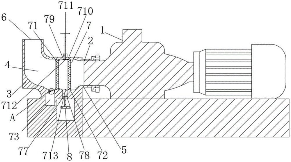
FIG. 1 is a longitudinal section of the present invention;
FIG. 2 is an enlarged view of the portion A of FIG. 1;
fig. 3 is a schematic view of the structure of the cleaning ring of the present invention.
In the figure: the device comprises a pump body 1, a first water inlet 2, a filter box 3, a flow passing groove 4, a connecting port 5, a second water inlet 6, a filter mechanism 7, a first filter screen 71, a second filter screen 72, a first collecting groove 73, a door sealing plate 74, a telescopic rod 75, a spring 76, a second collecting groove 77, a plug 78, a cleaning ring 79, a barb 710, a handle 711, a detaching groove 712, a detaching block 713 and a rod 8T.
Detailed Description
The technical solutions in the embodiments of the present invention will be described clearly and completely below with reference to the embodiments of the present invention, and it is obvious that the described embodiments are only some embodiments of the present invention, not all embodiments. Based on the embodiments in the present invention, all other embodiments obtained by a person skilled in the art without creative work belong to the protection scope of the present invention.
Referring to fig. 1-3, the present invention provides a technical solution: a corrosion-resistant centrifugal pump comprises a pump body 1, wherein a first water inlet 2 is formed in one side of the pump body 1, a filter box 3 is arranged at the position of the first water inlet 2, a flow passing groove 4 is formed in the interior of the filter box 3, a connecting port 5 is formed in one side, close to the first water inlet 2, of the filter box 3, a second water inlet 6 is formed in the top of the filter box 3, the connecting port 5 is communicated with the first water inlet 2 of the pump body 1, water flow is poured into the flow passing groove 4 through the second water inlet 6 and then enters the interior of the pump body 1 under the action of suction force generated by an impeller, and a filter mechanism 7 is arranged in the flow;
the filtering mechanism 7 comprises a first filtering net 71 and a second filtering net 72, the diameter of the filtering hole of the first filtering net 71 is larger than that of the second filtering net 72, the first filtering net 71 is positioned on one side of the second filtering net 72 far away from the second water inlet 6, double-layer filtering can be realized, accumulation of particles with different sizes is avoided, a better filtering effect is achieved, the inner wall of the overflowing groove 4 positioned under the second water inlet 6 is arc-shaped, the second water inlet 6 enables water to be connected into the overflowing groove 4, the impact force of the water is reduced through the arc-shaped diversion of the overflowing groove 4, the service lives of the first filtering net 71 and the second filtering net 72 are further prolonged, a first collecting groove 73 is formed in the bottom of the first filtering net 71, a door sealing plate 74 is arranged at the top of the first collecting groove 73, one side of the door sealing plate 74 is hinged to the inner wall of the first collecting groove 73, the other side of the door sealing plate 74, the bottom of the door sealing plate 74 and the inner wall of the first collecting groove 73 are connected by an expansion link 75, the expansion link 75 is a cylindrical structure composed of a hollow rod and a round rod, the hollow rod is inserted into the hollow rod in clearance fit, two ends of the expansion link 75 are respectively hinged with the door sealing plate 74 and the inner wall of the first collecting groove 73, a spring 76 is arranged in the expansion link 75, when slightly heavy inherent particles fall onto the upper surface of the door sealing plate 74, the door sealing plate 74 is stressed to contract the spring 76, so that the expansion link 75 is driven to be stressed to contract, the particles enter the first collecting groove 73 along gaps, a collecting door is arranged on the front surface of the first collecting groove 73, the collecting groove 73 with larger contrast solid particles can be opened for collecting, the bottom of the second filter screen 72 is provided with a second collecting groove 77, the second collecting groove 77 is provided with an inner part provided with a plug 78, and the plug 78 is, therefore, the second collecting groove 77 is convenient to open, the sealing effect of the threaded connection mode is good, the cleaning ring 79 is arranged at the top of the second filter screen 72, the plurality of barbs 710 are arranged on the outer surface of the cleaning ring 79, the handle 711 is arranged at the top of the cleaning ring 79, the top of the handle 711 penetrates through the filter box 3 and extends to the outside of the filter box 3, the handle 711 is in threaded connection with the filter box 3, the cleaning ring 79 is in threaded connection with the handle 711, the bottom of the cleaning ring 79 is provided with the dismounting groove 712, the top of the plug 78 is provided with the dismounting block 713, the barbs 710 are used for hooking some fiber products and fine particles attached to the second filter screen 72 to the upper side of the second collecting groove 77, then the falling particles are cleaned by opening the plug 78, the fiber trash falling on the barbs 710 is difficult to remove, and after the dismounting block 713 enters the dismounting groove 712, the handle 711 is still rotated to drive the screw between the cleaning ring 79 and the handle 711, and the handle 711 and the cleaning ring 79 are disassembled, so that the barb 710 can be cleaned directly.
Two ends of the first filter screen 71 and the second filter screen 72 are respectively fixedly connected with the inner wall of the overflow groove 4, and the first filter screen 71 and the second filter screen 72 are respectively welded on the inner wall of the overflow groove 4.
The pump body 1 passes through flange fixed connection with 5 departments of the connector of rose box 3, so conveniently dismantles rose box 3, can select whether to carry out the water according to the service environment at pump body 1 place and filter.
The detaching block 713 is a square structure, and the detaching groove 712 is a square groove, so that the cleaning ring 79 is fixed and cannot rotate along with the handle 711.
The T-shaped rod 8 is arranged at the bottom of the plug 78, and the T-shaped rod 8 is welded with the plug 78, so that the plug 78 can be conveniently operated.
The length and the width of second collecting vat 77 all are greater than the diameter of cleaning circle 79, so set up that cleaning circle 79 can drop from the inside of second collecting vat 77, conveniently clean it.
The barbs 710 are uniformly distributed on the circumferential surface of the cleaning ring 79, and the barbs 710 are attached to the filtering holes of the second filtering net 72, so that the cleaning effect is improved.
The working principle is as follows: assemble rose box 3 with the pump body 1, through the inside of second water inlet 6 with the leading-in overflow groove 4 of water, the cambered surface through overflow groove 4 leaves to first filter screen 71, first filter screen 71 carries out prefiltration to granule in the rivers, second filter screen 72 filters once more to granule in the rivers, rivers are in the inside that gets into the pump body 1 through connector 5, when needs clearance impurity, open first collecting vat 73 and correspond cleanly, then rotatory handle 711 drives clean circle 79 and moves down, barb 710 falls fibrous product and tiny particle hook, then rotatory end cap 78 corresponds cleanly.
Although embodiments of the present invention have been shown and described, it will be appreciated by those skilled in the art that changes, modifications, substitutions and alterations can be made in these embodiments without departing from the principles and spirit of the invention, the scope of which is defined in the appended claims and their equivalents.