CN212471380U - Special support capable of adjusting angle of assembly - Google Patents
Special support capable of adjusting angle of assembly Download PDFInfo
- Publication number
- CN212471380U CN212471380U CN202020576042.0U CN202020576042U CN212471380U CN 212471380 U CN212471380 U CN 212471380U CN 202020576042 U CN202020576042 U CN 202020576042U CN 212471380 U CN212471380 U CN 212471380U
- Authority
- CN
- China
- Prior art keywords
- upright post
- fixed
- stand
- angle
- column
- Prior art date
- Legal status (The legal status is an assumption and is not a legal conclusion. Google has not performed a legal analysis and makes no representation as to the accuracy of the status listed.)
- Active
Links
Images


Landscapes
- Photovoltaic Devices (AREA)
- Roof Covering Using Slabs Or Stiff Sheets (AREA)
Abstract
The utility model relates to a but special stand of regulating assembly angle, it includes front column and rear column, and the front column bottom links to each other with the ground rail or directly is fixed with the roof, and the bottom of rear column is fixed with the ground rail or directly with the roof, and the briquetting is passed through at the top of front column and rear column and is linked to each other with solar energy component. The special support capable of adjusting the angle of the assembly is improved by the structures of the front stand column and the rear stand column, the inclination angle of the assembly is determined, the angle is adapted through the stand column movable heads, the inclination angle of the solar assembly can be conveniently adjusted, the solar assembly on the roof forms the optimal power generation angle, the maximum power generation amount is obtained, the support is light in weight, the supporting leg with large weight is not required to be additionally arranged, and the roof cannot exceed the design bearing. Meanwhile, the height of the stand column can be adjusted by a method of fixing the two upper stand columns and the lower stand columns through different through holes, so that the inclination angle of the solar array can be manually adjusted according to seasons or months, and the maximum power generation capacity is achieved.
Description
Technical Field
The utility model relates to a but special stand of regulating assembly angle belongs to solar energy support subassembly technical field.
Background
At present, when a solar power station is installed on a plurality of light steel roofs, a straight-laying type support is generally adopted, and the inclination angle is the fixed angle of the roofs, so that the optimal generated energy cannot be obtained, and particularly the lost generated energy of the power station installed on the north slope of the light steel roofs is larger. The roof is especially suitable for the light steel roof, and the bearing of the light steel factory building is easy to exceed the design after the guide rails and the support legs are installed on the roof, so that the safety of the factory building is affected, and therefore the solar power station on the roof needs a special support which is light in weight and can adjust the angle of the component to the optimal angle so as to achieve the maximum power generation. Although some supports partially solve the problem, wind load and other factors are not considered, and the structure of the upright post is not good, so that the angle adjustable and the use occasions of the solar support are limited.
SUMMERY OF THE UTILITY MODEL
An object of the utility model is to overcome above-mentioned not enough, provide a weight is lighter, can the wide use, can conveniently adjust solar energy component inclination to can batch production not receive angle and environmental restriction, install simple but a special stand of regulating assembly angle.
The purpose of the utility model is realized like this:
the utility model provides a special stand of adjustable subassembly angle, it includes front column and rear column, and the bottom and the ground rail or the roof of front column, rear column are fixed, and the top of front column and rear column passes through the briquetting and links to each other with solar energy component, solar energy component is violently put or erects on front column and rear column, the height difference of front column and rear column to rear column top has the activity head, thereby through the inclination of activity head adjustment solar energy component, and front column, rear column all have two kinds of structures at least.
The first structure of the front upright post is as follows: the front upright post comprises a movable part and a front upright post base, the movable part is hinged to the front upright post base through a hinge shaft, a blind hole is formed in the top of the movable part, a pressing block is placed on the blind hole and fixed with the movable part, and the top of the pressing block is fixed with the solar module.
The second structure of the front upright post is as follows: the front column comprises stand, lower fixing base, last fixing base, activity head, and the upper and lower both ends of stand are fixed in the blind hole of fixing base top and last fixing base bottom down, and the top of going up the fixing base is articulated through the articulated shaft bottom the activity head, the blind hole is seted up at activity top, and the briquetting is put on the blind hole and is fixed with the activity head, and the briquetting top is fixed with solar energy component.
The lower fixing seat of the front upright post of the second structure is fixed with the ground rail, the center of the bottom of the lower fixing seat is upwards provided with a groove or a through hole for the ground rail to pass through, and the ground rail is fixed with the lower fixing seat.
The first structure of the rear upright post is the same as the front upright post of the second structure.
An inclined strut is arranged between the ground rail of the rear upright post and the upright post, and two ends of the inclined strut are fixed with the upright post and the ground rail.
The two ends of the inclined strut are respectively fixed with the upright post ground rail through locking pieces.
The second structure of the rear upright post is as follows: the rear upright column comprises a base, a stepped upright column and a movable head at the top, the stepped upright column comprises a plurality of layers of supports from top to bottom, the support at the upper layer is fixed on the support at the lower layer to form a stepped shape, the bottom of the stepped upright column is connected with the base, the base is fixed on the ground or a roof, the movable head is installed at the top of the stepped upright column, a blind hole is formed in the top of the movable head, a pressing block is placed on the blind hole and fixed with the movable head, and the top of the pressing block is fixed with the solar module.
The stand of front column second kind of structure can also adopt upper and lower two-section stand, and upper column one end is fixed in the blind hole of last fixing base bottom, and lower stand one end is fixed in the blind hole at fixing base top down, all is equipped with the horizontal through-hole of a plurality of on upper column, the lower stand, and upper column, lower stand pass through the overall height of horizontal through-hole regulation stand to adjust solar array's inclination.
The utility model relates to a but special stand of regulating assembly angle has following advantage:
the special support capable of adjusting the angle of the assembly is improved by the structures of the front stand column and the rear stand column, the inclination angle of the solar assembly can be conveniently adjusted, the solar assembly on the roof forms the optimal power generation angle, the maximum power generation amount is obtained, the support is light in weight, the supporting leg with large weight does not need to be additionally arranged, and the roof cannot exceed the design bearing.
Drawings
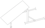
Fig. 1 is a schematic diagram of the first form of the special bracket assembly with adjustable assembly angle of the present invention and the installation of the horizontal and vertical solar energy assembly.
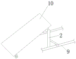
Fig. 2 is a schematic diagram of the second form of the special bracket assembly with adjustable assembly angle of the present invention and the installation of the horizontal and vertical solar energy assembly.
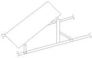
Fig. 3 is a schematic diagram of the third form of the special bracket with adjustable component angle of the present invention and the installation of the horizontal and vertical solar energy components.
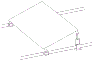
Fig. 4 is a schematic diagram of a fourth form of the special bracket assembly with adjustable assembly angle of the present invention and a solar module placed horizontally and vertically.
Fig. 5 is a schematic view of the installation of the solar module when the rear pillar of the present invention adopts the second structure.
Fig. 6 is a schematic view of the solar module of fig. 5 using a ground rail.
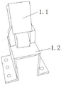
Fig. 7 is a schematic view of a first configuration of front pillars when the bottom surface is not connected.
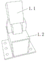
Fig. 8 is a schematic view of the bottom surface of the front pillar when attached in a first configuration.
Fig. 9 is a schematic view of a second configuration of the front pillar.
Fig. 10 is a second structural schematic diagram of the rear pillar.
Fig. 11 is a schematic view of the second structure of fig. 10 with the movable head removed from the top of the rear pillar.
Fig. 12 is a schematic view of the rear pillar of fig. 9 with the addition of braces and ground rails.
FIG. 13 is a first fitting relationship diagram of the upper and lower uprights when the front upright is adjustable in height.
FIG. 14 is a second relationship diagram of the upper and lower uprights when the front upright is adjustable in height.
FIG. 15 is a third diagram of the engagement between the upper and lower uprights when the front upright is adjustable in height.
In the figure: front column 1, moving part 1.1, front column base 1.2, back column 2, stand 3, upper column 3.1, lower column 3.2, lower fixing base 4, upper fixing base 5, movable head 6, bracing 7, locking piece 8, ground rail 9, solar energy component 10, base 11, step stand 12.
Detailed Description
Referring to fig. 1 to 15, the utility model relates to a special stand of adjustable subassembly angle, it includes front column 1 and rear column 2, and the bottom of front column 1, rear column 2 links to each other with ground rail 9 or directly is fixed with the roof, fixes solar energy component 10 at the top of front column 1 and rear column 2 through the briquetting.
The front upright post 1 has at least two structures:
the first structure is as follows: as shown in fig. 7 and 8, the front pillar 1 is composed of a movable member 1.1 and a front pillar base 1.2, the movable member 1.1 is hinged to the front pillar base 1.2 through a hinge shaft, a blind hole is formed in the top of the movable member 1.1, a press block is placed on the blind hole and is fixed to the movable member 1.1 by screwing a bolt on the press block with a nut preset or placed under the blind hole when being installed, the top of the press block is fixed to the solar module, the lower portion of the front pillar base 1.2 can be in a shape of a Chinese character 'kou' or a trapezoid or other shapes (matching the shape of the ground rail 9), when the lower portion of the base 1.2 is in a shape of a Chinese character 'kou', the left and right horizontal bottom surfaces of the front pillar base 1.2 can be connected or not connected, the bottom of the front pillar 1 is connected to the ground rail 9, or the bottom of the front pillar 1 is directly fixed to the roof, when the bottom of the front pillar 1 is connected to the ground rail 9, the center, or the lower part of the front upright column base 1.2 is provided with a rectangular through hole for the ground rail 9 to pass through. In addition, the two bottom surfaces can be wholly or partially connected or not connected, and can also extend forwards and backwards in the direction of the ground rail 9 so as to increase the area of the bottom surfaces, improve the adhesion with the bottom surfaces and improve the stability of the upright post.
The second structure is as follows: as shown in fig. 9, the front pillar 1 is composed of a pillar 3, a lower fixing seat 4, an upper fixing seat 5, and a movable head 6, wherein the upper and lower ends of the pillar 3 are fixed in blind holes at the top of the lower fixing seat 4 and the bottom of the upper fixing seat 5, the top of the upper fixing seat 5 is hinged with the bottom of the movable head 6 through a hinge shaft, the top of the movable head 6 is provided with a blind hole, a press block is placed on the blind hole to be fixed with the movable head 6, the top of the press block is fixed with a solar module, the lower fixing seat 4 is the same as the front pillar base 1.2 of the front pillar of the first structure, the bottom of the front pillar 1 is connected with a ground rail 9, or the bottom of the front pillar 1 is directly fixed with a roof, when the bottom of the front pillar 1 is connected with the ground rail 9, the center of the bottom of the lower fixing seat 4 is designed with a groove to block the ground rail 9, or the lower part of, or all or part of the bottom surfaces can be connected to form a whole surface or a rectangular annular bottom surface, and the bottom surfaces can also extend forwards and backwards along the direction of the ground rail 9 so as to enlarge the bottom surfaces and improve the adhesion with the bottom surfaces and the stability of the upright posts.
The rear upright post 2 has at least two structures:
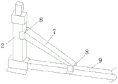
the first structure is as follows: as shown in fig. 9, the rear column 2 of the first structure is the same as the front column 1 of the second structure, and meanwhile, since the rear column 2 is higher, in order to improve the strength and stability of the rear column, the inclined strut 7 can be arranged between the ground rail 9 and the column 3, or the inclined strut 7 is not arranged, when the inclined strut 7 is arranged, the two ends of the inclined strut 7 are respectively fixed with the column 3 and the ground rail 9 through the locking piece 8, so that the overall strength and stability of the rear column 2 are improved, and the inclined strut 7 can be directly fixed with the ground rail 9 of the column 3 through screws, self-tapping screws, electric welding, hot melting and other methods.
The second structure is as follows: as shown in fig. 10 and 11, the rear pillar 2 is composed of a base 11, a step pillar 12 and a top movable head 6, the step pillar 12 is composed of a plurality of layers of supports 12.1 from top to bottom, the support of the upper layer is fixed on the support of the lower layer to form a step shape, a through hole is arranged in the middle of the support 12.1 of the lowest layer for the ground rail 9 to pass through, and the through hole can be omitted or the ground rail 9 is not used for reinforcement. The bottom of the stepped upright post 12 is connected with the base 11, the base 11 is fixed on a roof or the ground, the movable head 6 is installed at the top of the stepped upright post 12, the top of the movable head 6 is provided with a blind hole, a pressing block is placed on the blind hole and is fixed with the movable head 6 in a manner that a bolt in the pressing block is screwed with a nut preset in the blind hole or a nut placed during installation, and the top of the pressing block is fixed with the solar module.
The bottom surface of the base 11 can be a whole surface, can also be a rectangular annular surface, and can also be added with a plurality of horizontal strip-shaped surfaces in the hollow of the rectangular annular surface. In order to increase the stability and strength of the upright post, when the bottom surface of the base 11 is connected with the step-shaped upright post 12, a plurality of reinforced support ribs in all directions can be arranged for connection, when each layer of support 12.1 is connected with one layer of support 12.1, a plurality of reinforced support ribs in all directions can be arranged for connection, in order to enhance the strength, the connection surface of the upper layer of support 12.1 and the lower layer of support 12.1 can be designed into a whole surface or a rectangular annular surface, and a plurality of horizontal strip surfaces can be added into the hollow of the rectangular annular surface to enhance the stability of the supports.
When the front upright post 1 and the rear upright post 2 form a support, the bottom of the front upright post 1 and the bottom of the rear upright post 2 can be connected with the ground rail 9 or not connected with the ground rail 9, and the front upright post 1 and the rear upright post 2 respectively have various structures and can be horizontally placed or vertically placed together with the solar assembly. The front column 1 and the rear column 2 support and fix the solar assembly, different heights and intervals are adopted through the two support columns to form an assembly inclination angle, the movable part at the top is adapted to the angle, the pressing block can be further driven to be adjusted in place, the solar assembly on the pressing block is adjusted to a proper angle, the angle adjustment of the solar assembly can be conveniently achieved, the maximum generated energy of the assembly is achieved, the whole weight of the support is light, and the solar assembly support is suitable for various roofs.
In addition, the second structure of the front upright post (namely the first structure of the rear upright post) is composed of an upright post 3, a lower fixed seat 4, an upper fixed seat 5 and a movable head 6. If the distance between the front and rear uprights is determined, the angle of inclination of the assembly can be varied by selecting different heights for the uprights 3. If the column 3 is of a fixed length, once the solar array is built, the angle of the whole array is not adjustable. Therefore stand 3 can also adopt last stand 3.1, this upper and lower two-section stand of lower stand 3.2, the upper end of going up stand 3.1 is fixed in the blind hole of last fixing base 5 bottom, the lower extreme of lower stand 3.2 is fixed in the blind hole at 4 tops of lower fixing base, go up stand 3.1, all be equipped with the horizontal through-hole of a plurality of on the stand 3.2 down, it is fixed through selecting for use different horizontal through-holes between two stands, realize altitude mixture control, thereby can seasonally manual regulation solar array's inclination.
The fixing method between the upper upright post 3.1 and the lower upright post 3.2 is not less than the following three methods:
the first method comprises the following steps: as shown in fig. 13, a plurality of fixing through holes are formed in both the upper upright column 3.1 and the lower upright column 3.2, the upper upright column 3.1 and the lower upright column 3.2 are fixed together by bolts sequentially penetrating through the through holes of the upper and lower upright columns, and different through holes are selected for fixing when the height is adjusted. Meanwhile, before the angle is adjusted, fixing bolts on the middle pressing block or the side pressing block on the movable head are loosened, during angle adjustment, the middle pressing or the side pressing on the movable head and the movable head can move along the upper edge and the lower edge of the frame of the component, after the angle adjustment is finished, the movable head and the middle pressing or the side pressing are well positioned, and then the bolts on the pressing block are screwed down.
And the second method comprises the following steps: as shown in fig. 14, the lower upright 3.2 is hollow, the upper upright 3.1 is inserted into the hollow interior of the lower upright 3.2, a plurality of horizontal fixing through holes are formed in the upper upright 3.1 and the lower upright 3.2, and the heights of the uprights are adjusted by passing bolts through different horizontal fixing through holes between the upper upright and the lower upright. Meanwhile, the fixing bolt on the middle pressing block or the side pressing block on the movable head is loosened before the angle is adjusted, during the angle adjustment, the middle pressure or the side pressure on the movable head and the movable head can move along the upper edge and the lower edge of the frame of the component, after the angle adjustment is finished, the movable head and the middle pressure or the side pressure are well positioned, and then the bolt on the pressing block is screwed down.
And the third is that: as shown in fig. 15, the upper upright 3.1 is hollow, the lower upright 3.2 is inserted into the hollow of the upper upright 3.1, the upper and lower uprights have been provided with a plurality of horizontal fixing through holes, different through holes between the upper and lower uprights are fixed by bolts, and the height of the uprights is adjusted. Meanwhile, the bolt of the middle pressing block or the side pressing block on the movable head is loosened before the angle is adjusted, during the angle adjustment, the middle pressing or the side pressing on the movable head and the movable head can move along the upper edge and the lower edge of the frame of the component, after the angle adjustment is finished, the movable head and the middle pressing or the side pressing are well positioned, and then the bolt on the pressing block is screwed down.
Other fixing methods are also provided between the upper and lower upright columns, for example, the upper and lower upright columns are fixed by a metal plate in an interconnecting way, and the bottom of the center of the iron plate is provided with two holes which are fixed with the lower upright column; the iron plate is provided with a plurality of holes which are fixed with the upper upright post. Meanwhile, the plurality of fixing holes of the upper stand column are gradually changed from small to large in angle of the solar array, a moving track of the fixing holes is left on the iron plate, holes are dug along the track, the upper stand column is fixed along different points on the holes, the angle of the solar assembly can be adjusted by corresponding to different angles of the assembly through selecting different points on the track holes according to seasonal changes, and therefore the maximum power generation amount in the season or in the month is achieved.
The upper upright post 3.1 can be produced together with the upper fixing seat 5, the lower upright post 3.2 can be produced together with the lower fixing seat 4, the purposes of reducing installation procedures and saving cost are achieved, and the working principle is similar to that of the upper upright post.
Claims (9)
1. The utility model provides a special stand of adjustable subassembly angle which characterized in that: the solar energy assembly comprises a front upright post and a rear upright post, wherein the bottoms of the front upright post and the rear upright post are fixed with a ground rail or a roof, the tops of the front upright post and the rear upright post are connected with a solar energy assembly through a pressing block, the solar energy assembly is transversely or vertically placed on the front upright post and the rear upright post, the heights of the front upright post and the rear upright post are different, and the top of the rear upright post is provided with a movable head, so that the inclination angle of the solar energy assembly is adjusted through the movable head, and the front upright post and the rear upright post are provided with at least two structures.
2. The special bracket capable of adjusting the angle of the component as claimed in claim 1, wherein: the first structure of the front upright post is as follows: the front upright post comprises a movable part and a front upright post base, the movable part is hinged to the front upright post base through a hinge shaft, a blind hole is formed in the top of the movable part, a pressing block is placed on the blind hole and fixed with the movable part, and the top of the pressing block is fixed with the solar module.
3. The special bracket capable of adjusting the angle of the component as claimed in claim 1, wherein: the second structure of the front upright post is as follows: the front column comprises stand, lower fixing base, last fixing base, activity head, and the upper and lower both ends of stand are fixed in the blind hole of fixing base top and last fixing base bottom down, and the top of going up the fixing base is articulated through the articulated shaft bottom the activity head, the blind hole is seted up at activity top, and the briquetting is put on the blind hole and is fixed with the activity head, and the briquetting top is fixed with solar energy component.
4. The special bracket capable of adjusting the angle of the component as claimed in claim 3, wherein: the lower fixing seat of the front upright post of the second structure is fixed with the ground rail, the center of the bottom of the lower fixing seat is upwards provided with a groove or a through hole for the ground rail to pass through, and the ground rail is fixed with the lower fixing seat.
5. The special bracket capable of adjusting the angle of the component as claimed in claim 3, wherein: the first structure of the rear upright post is the same as the front upright post of the second structure.
6. The special bracket capable of adjusting the angle of the component as claimed in claim 5, wherein: an inclined strut is arranged between the ground rail of the rear upright post and the upright post, and two ends of the inclined strut are fixed with the upright post and the ground rail.
7. The special bracket capable of adjusting the angle of the component as claimed in claim 6, wherein: the two ends of the inclined strut are respectively fixed with the upright post ground rail through locking pieces.
8. The special bracket capable of adjusting the angle of the component as claimed in claim 1, wherein: the second structure of the rear upright post is as follows: the rear upright column comprises a base, a stepped upright column and a movable head at the top, the stepped upright column comprises a plurality of layers of supports from top to bottom, the support at the upper layer is fixed on the support at the lower layer to form a stepped shape, the bottom of the stepped upright column is connected with the base, the base is fixed on the ground or a roof, the movable head is installed at the top of the stepped upright column, a blind hole is formed in the top of the movable head, a pressing block is placed on the blind hole and fixed with the movable head, and the top of the pressing block is fixed with the solar module.
9. The special bracket capable of adjusting the angle of the component as claimed in claim 3, wherein: two-section stand about the stand of front column second kind structure adopts, goes up stand one end and fixes in the blind hole of last fixing base bottom, and stand one end is fixed down in the blind hole at fixing base top, all is equipped with the horizontal through-hole of a plurality of on going up stand, the lower stand, goes up stand, lower stand and passes through the overall height of horizontal through-hole regulation stand to adjust solar array's inclination.
Priority Applications (1)
| Application Number | Priority Date | Filing Date | Title |
|---|---|---|---|
| CN202020576042.0U CN212471380U (en) | 2020-04-17 | 2020-04-17 | Special support capable of adjusting angle of assembly |
Applications Claiming Priority (1)
| Application Number | Priority Date | Filing Date | Title |
|---|---|---|---|
| CN202020576042.0U CN212471380U (en) | 2020-04-17 | 2020-04-17 | Special support capable of adjusting angle of assembly |
Publications (1)
| Publication Number | Publication Date |
|---|---|
| CN212471380U true CN212471380U (en) | 2021-02-05 |
Family
ID=74450229
Family Applications (1)
| Application Number | Title | Priority Date | Filing Date |
|---|---|---|---|
| CN202020576042.0U Active CN212471380U (en) | 2020-04-17 | 2020-04-17 | Special support capable of adjusting angle of assembly |
Country Status (1)
| Country | Link |
|---|---|
| CN (1) | CN212471380U (en) |
Cited By (1)
| Publication number | Priority date | Publication date | Assignee | Title |
|---|---|---|---|---|
| CN111347378A (en) * | 2020-04-17 | 2020-06-30 | 江阴市新昶虹电力科技股份有限公司 | Special support capable of adjusting angle of assembly |
-
2020
- 2020-04-17 CN CN202020576042.0U patent/CN212471380U/en active Active
Cited By (1)
| Publication number | Priority date | Publication date | Assignee | Title |
|---|---|---|---|---|
| CN111347378A (en) * | 2020-04-17 | 2020-06-30 | 江阴市新昶虹电力科技股份有限公司 | Special support capable of adjusting angle of assembly |
Similar Documents
| Publication | Publication Date | Title |
|---|---|---|
| CN110578371B (en) | Super-huge steel structure supporting framework | |
| CN212471380U (en) | Special support capable of adjusting angle of assembly | |
| CN112311313A (en) | Automatic tracking device based on solar power generation | |
| CN214276186U (en) | Angle-adjustable solar support for cement roof | |
| CN111347378A (en) | Special support capable of adjusting angle of assembly | |
| CN213926989U (en) | Slope roof supporting structure | |
| CN209949032U (en) | Photovoltaic support with adjustable single pivot inclination | |
| CN203747731U (en) | Photovoltaic support characterized by vertical adjustability and convenient construction and support assembly | |
| CN216340083U (en) | Factory building steel skeleton texture that adaptability is high | |
| CN110677104A (en) | Angle-adjustable support and photovoltaic device | |
| CN217216411U (en) | A large-span flexible photovoltaic support | |
| CN217741612U (en) | A pin-connected panel solar rack system for saddle plate roof | |
| CN213094111U (en) | But angle regulation's solar rack's connection structure | |
| CN209823678U (en) | Photovoltaic bracket component suitable for low latitude area and combined frame thereof | |
| CN112178957A (en) | Angle-adjustable solar support for cement roof | |
| CN217486435U (en) | Adjustable photovoltaic board support convenient to installation | |
| CN207475450U (en) | A kind of adjustable photovoltaic support | |
| CN201327232Y (en) | Moveable heat pipe supporting frame for solar collector | |
| CN221305824U (en) | Height-adjustable new energy photovoltaic bracket | |
| CN219893245U (en) | But angle regulation's photovoltaic support that does not destroy waterproof | |
| CN220043295U (en) | Mountain region photovoltaic support | |
| CN218352440U (en) | High-strength photovoltaic panel support | |
| CN215072270U (en) | Ground photovoltaic support with adjustable inclination angle and mounting height | |
| CN220556714U (en) | But reuse's roofing photovoltaic mounting bracket | |
| CN216490353U (en) | Support is tracked to adjustable angle photovoltaic of greenhouse canopy |
Legal Events
| Date | Code | Title | Description |
|---|---|---|---|
| GR01 | Patent grant | ||
| GR01 | Patent grant |