Model structure for city planning
Technical Field
The utility model relates to a city planning technical field relates to a model structure that city planning used particularly.
Background
Along with modern continuous development, people pay more attention to the environment in the aspect of the house and around the house, a good living environment can be built only when the environment and the house are better, thereby bringing better life happiness for people, in the process of carrying out city planning or house selling, in order to make people more intuitively see the style of concrete city planning and the greening environment around the house clearly, generally all can choose the preparation sand table model, show house, road, green plant and peripheral facility according to the scale reduction use model, such a display mode is more intuitive and people know also can be more clear.
The existing city planning model is mainly a sand table model, the sand table is prepared in the manufacturing process, after the scaled-down model is manufactured, the model is pasted on the top of the sand table, all models are arranged according to positions, the model manufacturing is very simple, but the model is pasted on the sand table, so in the long-time placing process, the phenomenon that the model is paralyzed due to insufficient pasting force can occur, the service life of the whole model is short, the general model is displayed in an open mode, dust is easily accumulated and is inconvenient to clean, and the height of display crowds can not be adjusted, so that the waist of the display crowds is worried when the display crowds watch the sand table.
SUMMERY OF THE UTILITY MODEL
In view of the above-mentioned problem that prior art exists, an aspect of the utility model is to provide a model structure that city planning used aims at solving current city planning model life weak point, and is difficult clean and can't be to using crowd height-adjusting, leads to the narrow problem of application scope.
Technical scheme
In order to achieve the above object, the utility model provides a model structure for city planning, including shell and model, be equipped with elevating system in the shell, elevating system includes the motor, the top of elevating system is fixed with the mounting bracket, drive the motor, make the mounting bracket keep the straight-line motion in the vertical direction;
the slider is installed to the symmetry on the inner wall of the relative one side of mounting bracket, two sliding connection has the mounting panel on the outer wall of slider, the fixed orifices has been seted up at the top of mounting panel, the quantity of fixed orifices is a plurality of, the inserted bar is installed to the bottom surface symmetry of model, the quantity of inserted bar is a plurality of, and is a plurality of the inserted bar is with a plurality of the fixed orifices cooperatees and pegs graft.
Preferably, the lifting mechanism further comprises two threaded rods and two fixing rods, the two threaded rods are symmetrically axially connected to the edges of the two sides of the bottom surface of the shell, the two fixing rods are symmetrically installed on the edges of the two sides of the bottom surface of the shell, threaded sleeves are respectively in threaded connection with the outer walls of the two threaded rods, sliding sleeves are respectively in sliding connection with the outer walls of the two fixing rods, connecting rods are respectively and fixedly installed on the outer walls of the two threaded sleeves and the outer wall of the side, adjacent to the bottom surface, of the two threaded rods, guide wheels c are fixedly installed on the outer wall of the side, adjacent to the bottom surface, of the other threaded rod, guide wheels d are fixedly installed on the outer wall of the side, adjacent to the bottom surface, of the shell, a fixing plate is fixedly installed on the outer wall of, the output end of the motor is fixedly provided with a shaft rod, the other end of the shaft rod extends and is connected to the bottom surface of the shell in a shaft-to-shaft mode, a guide wheel a and a guide wheel b are fixedly installed on the outer wall of the shaft rod from top to bottom, the guide wheel a is in transmission connection with the guide wheel d through a belt a, and the guide wheel b is in transmission connection with the guide wheel c through a belt b.
Preferably, a fixture block is fixedly mounted on the outer wall of one side of the inserted rod adjacent to the model, and the fixture block is integrally made of rubber.
Preferably, the edge of the outer wall of one side of the adjacent top of the mounting frame is hinged with a baffle, and the baffle is integrally made of an acrylic material.
Preferably, the top of the baffle is symmetrically provided with a plurality of illuminating lamps.
As preferred, seted up on the outer wall of the positive one side of shell and stored the cabinet, the edge of storing the cabinet both sides outer wall all articulates there is the cabinet door.
Advantageous effects
Compared with the prior art, the utility model provides a pair of model structure that city planning was used possesses following beneficial effect:
1. the utility model discloses a, at the top equipment fixed orifices of mounting panel, be equipped with the inserted bar in the bottom surface of model, through the cooperation between inserted bar and the fixed orifices, fix the model on the mounting panel, the not enough phenomenon of viscidity can not appear, also very firm after the model is placed for a long time, the life of the whole model of growth.
2. The utility model discloses a, baffle all around is transparent and articulates on the mounting bracket, makes things convenient for the viewer to watch and the convenience gets off baffle upset all around, and mounting panel and mounting bracket support are sliding connection's structure, conveniently carries out the dismantlement work of mounting panel, and the clean work of carrying out whole device that such design can be very convenient operates also convenience very.
3. The utility model discloses a, the drive of transmission and motor between the utilization guide pulley for the mounting bracket can carry out the ascending and descending work in the vertical direction, to the different heights of the crowd of watching of difference, can be very convenient carry out the adjustment of model height.
It is to be understood that both the foregoing general description and the following detailed description are exemplary and explanatory only and are not restrictive of the disclosure.
This document provides an overview of various implementations or examples of the technology described in this disclosure, and is not a comprehensive disclosure of the full scope or all features of the disclosed technology.
Drawings
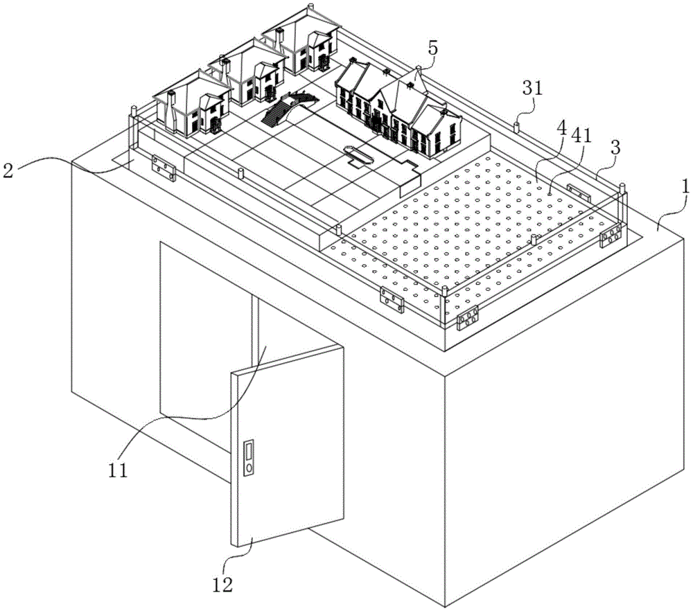
FIG. 1 is a schematic structural view of the present invention;
fig. 2 is a schematic view of the rear view angle section structure of the present invention;
FIG. 3 is a schematic side view cross-sectional view of the present invention;
fig. 4 is an enlarged schematic view of the utility model at a;
fig. 5 is a schematic diagram of the model structure of the present invention.
The main reference numbers:
1. a housing; 11. a storage cabinet; 12. a cabinet door; 13. a fixing plate; 2. a mounting frame; 21. a slider; 3. a baffle plate; 31. an illuminating lamp; 4. mounting a plate; 41. a fixing hole; 5. a model; 51. inserting a rod; 52. a clamping block; 6. a lifting mechanism; 61. a motor; 611. a guide wheel a; 612. a guide wheel b; 613. a shaft lever; 62. a belt a; 63. a belt b; 64. a threaded rod; 641. a guide wheel c; 642. a guide wheel d; 65. a threaded sleeve; 66. fixing the rod; 67. a sliding sleeve; 68. a connecting rod.
Detailed Description
In order to make the objects, technical solutions and advantages of the embodiments of the present disclosure more clear, the technical solutions of the embodiments of the present disclosure will be described below clearly and completely with reference to the accompanying drawings of the embodiments of the present disclosure. It is to be understood that the described embodiments are only a few embodiments of the present disclosure, and not all embodiments. All other embodiments, which can be derived by a person skilled in the art from the described embodiments of the disclosure without any inventive step, are within the scope of protection of the disclosure.
Unless otherwise defined, technical or scientific terms used herein shall have the ordinary meaning as understood by one of ordinary skill in the art to which this disclosure belongs. The use of the word "comprising" or "comprises", and the like, in this disclosure is intended to mean that the elements or items listed before that word, include the elements or items listed after that word, and their equivalents, without excluding other elements or items. The terms "connected" or "coupled" and the like are not restricted to physical or mechanical connections, but may also include electrical connections, whether direct or indirect. "upper", "lower", "left", "right", and the like are used merely to indicate relative positional relationships, and when the absolute position of the object being described is changed, the relative positional relationships may also be changed accordingly.
To maintain the following description of the embodiments of the present disclosure clear and concise, a detailed description of known functions and known components have been omitted from the present disclosure.
Referring to fig. 1-5, a model structure for city planning, including a housing 1 and a model 5, in the course of city planning in a section of area, the model 5 to be placed is completely manufactured, a mounting plate 4 is fixed with a mounting frame 2 through a sliding connection with a slide block 21, the model 5 is inserted into a fixing hole 41 through an insertion rod 51 at the bottom surface, and the insertion rod 51 is clamped into the fixing hole 41 by a clamping block 52, so that the model 5 can be firmly fixed on the mounting plate 4, after the installation of the model 5 is completed, the surrounding baffle plates 3 are turned over along the hinged joint to protect the periphery of the whole model 5, when the height of the model 5 needs to be adjusted, a motor 61 is started, the motor 61 can drive a guide wheel 613 to rotate, and a guide wheel a611 and a guide wheel shaft b612 which are fixedly mounted on the mounting plate 613 can rotate synchronously, because the transmission connection between the guide wheel a611 and the guide wheel d642 is in transmission with the guide wheel b612 and the guide wheel c641, make motor 61 can drive two threaded rods 64 when rotating and rotate, because thread bush 65 threaded connection is in the outer wall of threaded rod 64, so thread bush 65 can be along the outer wall rebound of threaded rod 64 when threaded rod 64 rotates to support mounting bracket 2 rebound, carry out the regulation of height, sliding connection's slip cap 67 is as the support of opposite side on the dead lever 66, the stability when guaranteeing mounting bracket 2 to rise, the very simple and easy to operate of process of whole operation.
As shown in fig. 1, the utility model discloses in the further technical scheme that provides, the edge of the adjacent top one side outer wall of mounting bracket 2 all articulates there is baffle 3, and baffle 3 specifically is made by ya keli material an organic whole, carries out simple protection work to model 5 through baffle 3.
Wherein, the light 31 is installed to the top symmetry of baffle 3, and the quantity of light 31 is a plurality of, and the light 31 can carry out the illumination work of model 5, can be with putting of model 5 more clear of shining.
Wherein, seted up on the outer wall of the positive one side of shell 1 and stored cabinet 11, the edge of storing 11 both sides outer walls of cabinet all articulates there is cabinet door 12, places storing cabinet 11, unusual convenience and make full use of the space at the article that the department of putting needs to prepare.
As shown in fig. 2 and fig. 3, the utility model discloses in the further technical scheme that provides, be equipped with elevating system 6 in the shell 1, elevating system 6 includes motor 61, and elevating system 6's top fixed mounting has mounting bracket 2, driving motor 61 for mounting bracket 2 keeps the ascending linear motion of vertical direction, carries out the altitude mixture control work of mounting bracket 2 through elevating system 6.
Wherein, the lifting mechanism 6 further comprises two threaded rods 64 and two fixing rods 66, the two threaded rods 64 and the two fixing rods 66 are respectively provided with two, the two threaded rods 64 are symmetrically connected at the edges of the two sides of the bottom surface of the shell 1 in an axial manner, the two fixing rods 66 are symmetrically arranged at the edges of the two sides of the bottom surface of the shell 1 in an axial manner, the outer walls of the two threaded rods 64 are respectively in threaded connection with a threaded sleeve 65, the outer walls of the two fixing rods 66 are respectively in sliding connection with a sliding sleeve 67, the outer walls of the two threaded sleeves 65 and the two sliding sleeves 67 adjacent to the opposite side of the bottom surface are respectively and fixedly provided with a connecting rod 68, the outer wall of one side of the threaded rod 64 adjacent to the bottom surface is fixedly provided with a guide wheel c641, the outer wall of one side of the other threaded rod 64 adjacent to the bottom, the other end of the shaft rod 613 extends and is coupled to the bottom surface of the housing 1, and the outer wall is fixedly provided with a guide wheel a611 and a guide wheel b612 from top to bottom, the guide wheel a611 is in transmission connection with the guide wheel d642 through a belt a62, the guide wheel b612 is in transmission connection with the guide wheel c641 through a belt b63, and the guide wheel a611 is in transmission connection with the guide wheel d642, the guide wheel b612 and the guide wheel c641, so that the rotation of the threaded rod 64 can be conveniently performed, and the purpose of height adjustment can be achieved.
As shown in fig. 4 and 5, the utility model discloses in the technical scheme that further proposes, slider 21 is installed to the symmetry on the inner wall of the relative one side of mounting bracket 2, sliding connection has mounting panel 4 on two slider 21's the outer wall, fixed orifices 41 have been seted up at mounting panel 4's top, the quantity of fixed orifices 41 is a plurality of, inserted bar 51 is installed to model 5's bottom surface symmetry, the quantity of inserted bar 51 is a plurality of, a plurality of inserted bar 51 and a plurality of fixed orifices 41 cooperate and peg graft, cooperation through between fixed orifices 41 and the inserted bar 51, the fixed work of model 5 that carries out that can be very convenient, and convenient to detach, it is fixed stable.
Wherein, fixed mounting has fixture block 52 on the outer wall of the adjacent model 5 one side of inserted bar 51, and fixture block 52 specifically is made by rubber an organic whole, and fixture block 52 can make the fixed very firm of model 5, and long-time putting also can not influence the show work of model 5.
The working principle is as follows:
1. the mounting plate 4 is fixed with the mounting frame 2 through the sliding connection with the sliding block 21, the model 5 is inserted into the fixing hole 41 through the insertion rod 51 on the bottom surface, and the insertion rod 51 is clamped into the fixing hole 41 by the clamping block 52, so that the model 5 can be firmly fixed on the mounting plate 4.
2. When the height of the model 5 needs to be adjusted, the motor 61 is started, the motor 61 can drive the shaft 613 to rotate, the guide wheel a611 and the guide wheel b612 which are fixedly installed on the shaft 613 can rotate synchronously, the motor 61 can drive the two threaded rods 64 to rotate when rotating due to the transmission connection between the guide wheel a611 and the guide wheel d642 and the transmission between the guide wheel b612 and the guide wheel c641, and the threaded sleeves 65 are in threaded connection with the outer walls of the threaded rods 64, so that the threaded sleeves 65 can move upwards along the outer walls of the threaded rods 64 when the threaded rods 64 rotate, so that the mounting frame 2 is supported to move upwards, the height is adjusted, the sliding sleeves 67 which are in sliding connection on the fixed rods 66 serve as supports of the other side, and the stability of the.
The electrical components presented in the document are all electrically connected with an external master controller and 220V mains, and the master controller can be a conventional known device controlled by a computer or the like.
The above embodiments are merely exemplary embodiments of the present invention, which is not intended to limit the present invention, and the scope of the present invention is defined by the appended claims. Various modifications and equivalents may be made by those skilled in the art to the present invention without departing from the spirit and scope of the invention, and such modifications and equivalents should be considered to be within the scope of the invention.