CN212456024U - Guide sliding mechanism for electrical mechanical equipment - Google Patents
Guide sliding mechanism for electrical mechanical equipment Download PDFInfo
- Publication number
- CN212456024U CN212456024U CN202020905008.3U CN202020905008U CN212456024U CN 212456024 U CN212456024 U CN 212456024U CN 202020905008 U CN202020905008 U CN 202020905008U CN 212456024 U CN212456024 U CN 212456024U
- Authority
- CN
- China
- Prior art keywords
- clamping
- mechanical equipment
- groove
- mounting
- rod
- Prior art date
- Legal status (The legal status is an assumption and is not a legal conclusion. Google has not performed a legal analysis and makes no representation as to the accuracy of the status listed.)
- Expired - Fee Related
Links
- 230000007246 mechanism Effects 0.000 title claims abstract description 59
- 238000009434 installation Methods 0.000 claims abstract description 12
- 238000013461 design Methods 0.000 abstract description 3
- 230000009471 action Effects 0.000 description 4
- 230000000903 blocking effect Effects 0.000 description 2
- 230000000694 effects Effects 0.000 description 2
- 230000000149 penetrating effect Effects 0.000 description 2
- 208000027418 Wounds and injury Diseases 0.000 description 1
- 230000002337 anti-port Effects 0.000 description 1
- 230000009286 beneficial effect Effects 0.000 description 1
- 230000005540 biological transmission Effects 0.000 description 1
- 230000008859 change Effects 0.000 description 1
- 230000006378 damage Effects 0.000 description 1
- 230000007547 defect Effects 0.000 description 1
- 230000006872 improvement Effects 0.000 description 1
- 208000014674 injury Diseases 0.000 description 1
- 238000007689 inspection Methods 0.000 description 1
- 238000012423 maintenance Methods 0.000 description 1
- 238000004519 manufacturing process Methods 0.000 description 1
- 230000002265 prevention Effects 0.000 description 1
Images

Landscapes
- Transmission Devices (AREA)
Abstract
The utility model discloses an electromechanical device is with direction slide mechanism, including framework and electromechanical device, be equipped with drive mechanism in the framework, sliding connection has the mounting panel in the framework, electromechanical device places the top at the mounting panel, the bottom fixed mounting of mounting panel has the dog, the dog extends to in the slewing mechanism, two spouts have been seted up on the mounting panel, the interior top of spout is run through and has been seted up the intercommunication groove, sliding connection has the slider in the spout, the lateral wall fixed mounting of slider has first pull rod, a plurality of first springs of fixedly connected with between the lateral wall of slider and the inside wall of spout, installation cavity and draw-in groove have been seted up on the slider, be equipped with slewing mechanism on the first spring. The utility model has the advantages of reasonable design, it can realize the installation and the dismantlement to mechanical equipment fast, convenient and fast, and can adapt to the mechanical equipment of different specifications, and application scope is wide.
Description
Technical Field
The utility model relates to a direction sliding equipment technical field especially relates to an electromechanical device is with direction slide mechanism.
Background
With the rapid development of society and the improvement of living standard, the variety of various electrical and mechanical equipment is more and has various characteristics, but has a lot of commonalities, so that the prevention of mechanical injury accidents can be enhanced from the aspects of design, manufacture, inspection, installation, use, good maintenance and operation environment of the electrical and mechanical equipment.
Through retrieval, chinese patent No. CN210344038U discloses a guide sliding mechanism for electrical mechanical equipment, which comprises a bottom plate, wherein both sides of the top end of the bottom plate are fixedly provided with a protection plate, both ends of the bottom plate are fixedly provided with a side plate, both ends of the two protection plates are respectively fixedly connected with both sides of the two side plates, the middle part of one side plate is fixedly provided with a step motor, and a transmission shaft of the step motor penetrates through the wall of one side plate and is fixedly connected with one end of a screw rod.
The existing sliding mechanism has the following defects: the sliding plate is provided with the fixing hole, the mechanical equipment is fixed through the bolt, the mechanical equipment is fixed, the installation and the disassembly are inconvenient, the fixing hole in the sliding plate is only suitable for the mechanical equipment with one specification, and the application range is small.
SUMMERY OF THE UTILITY MODEL
The utility model aims at solving the problem that current slide mechanism dismantles inconvenience and application scope is little to mechanical equipment's installation among the prior art, and the direction slide mechanism for electrical machinery equipment that proposes, it can realize fast that convenient and fast just can adapt to the mechanical equipment of different specifications with dismantling mechanical equipment, and application scope is wide.
In order to achieve the above purpose, the utility model adopts the following technical scheme:
a guide sliding mechanism for electrical mechanical equipment comprises a frame body and the electrical mechanical equipment, wherein a driving mechanism is arranged on the frame body, a mounting plate is connected onto the frame body in a sliding manner, the electrical mechanical equipment is placed at the top of the mounting plate, a stop block is fixedly installed at the bottom of the mounting plate and extends into a rotating mechanism, two sliding grooves are formed in the mounting plate, a communicating groove is formed in the inner top of each sliding groove in a penetrating manner, a sliding block is connected in each sliding groove in a sliding manner, a first pull rod is fixedly installed on the side wall of each sliding block, a plurality of first springs are fixedly connected between the side wall of each sliding block and the inner side wall of each sliding groove, a mounting cavity and a clamping groove are formed in each sliding block, a rotating mechanism is arranged on each first spring, a clamping mechanism is arranged on each communicating groove and is connected with the rotating mechanism in a threaded, the inner top of the sliding groove is provided with an installation groove, and a clamping mechanism is arranged in the installation groove.
Preferably, the driving mechanism comprises a screw rod rotatably connected in the frame body, a servo motor is fixedly mounted on the side wall of the frame body, and the tail end of an output shaft of the servo motor extends into the frame body and is fixedly connected with a rotating shaft of the screw rod.
Preferably, slewing mechanism is including rotating threaded rod and the dwang of connection on the slider, the bottom of threaded rod extends to installation intracavity and fixed mounting has first bevel gear, the one end of dwang extends to installation intracavity and fixed mounting has second bevel gear, the dwang meshes with second bevel gear mutually.
Preferably, the clamping mechanism comprises a clamping plate which is slidably connected in the communicating groove, the bottom of the clamping plate is abutted against the top of the base of the electrical mechanical equipment, and the clamping plate is in threaded connection with the threaded rod.
Preferably, the clamping mechanism includes the fixture block of sliding connection in the mounting groove, the top fixed mounting of fixture block has the second pull rod, the second pull rod runs through the mounting panel and rather than sliding connection, fixedly connected with second spring between the top of fixture block and the interior top of mounting groove, the bottom and the first pull rod of fixture block offset.
Preferably, the second spring is an elastic spring.
Compared with the prior art, the utility model, its beneficial effect does:
1. through establishment of slewing mechanism and clamping mechanism, when needs fix electromechanical device, rotate the dwang, the dwang drives second bevel gear and rotates, second bevel gear drives the threaded rod through the first bevel gear with it meshing and rotates, because threaded rod and splint threaded connection, the threaded rod is when rotating, splint lapse downwards, make the bottom of splint and the top of electromechanical device base counterbalance tightly, and then realized the fixed to electromechanical device fast, when needs dismantle electromechanical device get off, only need the antiport dwang can, high durability and convenient operation.
2. Through the establishment of first pull rod and chucking mechanism, when fixing the electromechanical device of different specifications, stimulate first pull rod, first pull rod drives the slider and outwards slides, the fixture block goes into the draw-in groove under the effect of second spring elasticity, distance between two splint reaches the maximum value, place electromechanical device between two splint, stimulate the second pull rod upwards, the fixture block breaks away from blockking to first pull rod, the slider slides under the effect of first spring elasticity, make the lateral wall of splint offset with the lateral wall of electromechanical device base, and then realized the fixed to the electromechanical device of different specifications.
To sum up, the utility model has the advantages of reasonable design, it can realize the installation and the dismantlement to mechanical equipment fast, convenient and fast, and can adapt to the mechanical equipment of different specifications, and application scope is wide.
Drawings
Fig. 1 is a schematic structural view of a guiding sliding mechanism for an electrical mechanical apparatus according to the present invention;
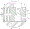
FIG. 2 is an enlarged view of the structure at A in FIG. 1;
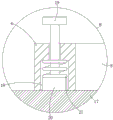
fig. 3 is an enlarged view of the structure at B in fig. 1.
In the figure: the device comprises a frame body 1, a screw rod 2, a servo motor 3, a mounting plate 4, a clamping plate 5, an electromechanical device 6, a sliding groove 7, a communicating groove 8, a sliding block 9, a first spring 10, a mounting cavity 11, a clamping groove 12, a threaded rod 13, a first bevel gear 14, a rotating rod 15, a second bevel gear 16, a first pull rod 17, a mounting groove 18, a second pull rod 19, a clamping block 20 and a second spring 21.
Detailed Description
The technical solutions in the embodiments of the present invention will be described clearly and completely with reference to the accompanying drawings in the embodiments of the present invention, and it is obvious that the described embodiments are only some embodiments of the present invention, not all embodiments.
Referring to fig. 1-3, a guiding sliding mechanism for an electrical mechanical device comprises a frame body 1 and an electrical mechanical device 6, wherein a driving mechanism is arranged on the frame body 1, the driving mechanism comprises a screw rod 2 rotatably connected in the frame body 1, a servo motor 3 is fixedly arranged on the side wall of the frame body 1, and the tail end of an output shaft of the servo motor 3 extends into the frame body 1 and is fixedly connected with a rotating shaft of the screw rod 2;
the frame body 1 is connected with a mounting plate 4 in a sliding manner, the electrical mechanical equipment 6 is placed at the top of the mounting plate 4, a stop block is fixedly installed at the bottom of the mounting plate 4 and extends into a rotating mechanism, two sliding grooves 7 are formed in the mounting plate 4, a communicating groove 8 is formed in the inner top of each sliding groove 7 in a penetrating manner, a sliding block 9 is connected in each sliding groove 7 in a sliding manner, a first pull rod 17 is fixedly installed on the side wall of each sliding block 9, a plurality of first springs 10 are fixedly connected between the side wall of each sliding block 9 and the inner side wall of each sliding groove 7, a mounting cavity 11 and a clamping groove 12 are formed in each sliding block 9, a rotating mechanism is arranged on each first spring 10 and comprises a threaded rod 13 and a rotating rod 15 which are rotatably connected onto each sliding block 9, the bottom end of each threaded rod 13 extends into the mounting cavity 11, the rotating rod 15 is meshed with a second bevel gear 16;
the communicating groove 8 is provided with a clamping mechanism, the clamping mechanism is in threaded connection with a rotating mechanism, the clamping mechanism is abutted against the top of the base of the electrical mechanical equipment 6, the clamping mechanism comprises a clamping plate 5 which is in sliding connection with the communicating groove 8, the bottom of the clamping plate 5 is abutted against the top of the base of the electrical mechanical equipment 6, the clamping plate 5 is in threaded connection with a threaded rod 13, through the establishment of the rotating mechanism and the clamping mechanism, when the electrical mechanical equipment 6 needs to be fixed, the rotating rod 15 is rotated, the rotating rod 15 drives the second bevel gear 16 to rotate, the second bevel gear 16 drives the threaded rod 13 to rotate through a first bevel gear 14 which is meshed with the second bevel gear, as the threaded rod 13 is in threaded connection with the clamping plate 5, the clamping plate 5 slides downwards when the threaded rod 13 rotates, the bottom of the clamping plate 5 is abutted against the top of the base of the electrical mechanical, when the electromechanical device 6 needs to be disassembled, the rotating rod 15 only needs to be rotated reversely, and the operation is simple;
the inner top of the sliding groove 7 is provided, the mounting groove 18 is internally provided with a clamping mechanism, the clamping mechanism comprises a clamping block 20 which is connected in the mounting groove 18 in a sliding manner, the top of the clamping block 20 is fixedly provided with a second pull rod 19, the second pull rod 19 penetrates through the mounting plate 4 and is connected with the mounting plate in a sliding manner, a second spring 21 is fixedly connected between the top of the clamping block 20 and the inner top of the mounting groove 18, the second spring 21 is an elastic spring, the bottom of the clamping block 20 is abutted against the first pull rod 17, through the arrangement of the first pull rod 17 and the clamping mechanism, when the electromechanical equipment 6 with different specifications is fixed, the first pull rod 17 is pulled, the first pull rod 17 drives the sliding block 9 to slide outwards, the clamping block 20 slides into the clamping groove 12 under the action of the elastic force of the second spring 21, the distance between the two clamping plates 5 reaches the maximum value, the electromechanical equipment 6 is placed between, the fixture block 20 is separated from blocking the first pull rod 17, and the slide block 9 slides under the action of the elastic force of the first spring 10, so that the side wall of the clamping plate 5 is abutted against the side wall of the base of the electrical mechanical equipment 6, and further the electrical mechanical equipment 6 with different specifications is fixed.
The utility model discloses its functional principle is explained to following mode of operation of accessible:
in the utility model, when the electrical mechanical device 6 needs to be fixed, the first pull rod 17 is pulled, the first pull rod 17 drives the slider 9 to slide outwards, the fixture block 20 slides into the clamping groove 12 under the action of the elastic force of the second spring 21, the distance between the two clamping plates 5 reaches the maximum value, the electrical mechanical device 6 is placed between the two clamping plates 5, the second pull rod 19 is pulled upwards, the fixture block 20 is separated from the blocking of the first pull rod 17, the slider 9 slides under the action of the elastic force of the first spring 10, so that the side wall of the clamping plate 5 is abutted against the side wall of the base of the electrical mechanical device 6, then the rotating rod 15 is rotated, the rotating rod 15 drives the second bevel gear 16 to rotate, the second bevel gear 16 drives the threaded rod 13 to rotate through the first bevel gear 14 meshed with the second bevel gear 16, because the threaded rod 13 is in threaded connection with the clamping plate 5, when the threaded rod 13 rotates, the clamping plate 5 slides downwards, so that the bottom of the, and then realized fixing electromechanical device 6 fast, to electromechanical device 6 after finishing fixing, start servo motor 3, servo motor 3 drives lead screw 2 and rotates, drives mounting panel 4 on the dog and removes when lead screw 2 rotates, and then has realized the slip of electromechanical device 6.
The above, only be the concrete implementation of the preferred embodiment of the present invention, but the protection scope of the present invention is not limited thereto, and any person skilled in the art is in the technical scope of the present invention, according to the technical solution of the present invention and the utility model, the concept of which is equivalent to replace or change, should be covered within the protection scope of the present invention.
Claims (6)
1. The utility model provides a direction slide mechanism for electrical machinery equipment, includes framework (1) and electrical machinery equipment (6), its characterized in that, be equipped with drive mechanism on framework (1), sliding connection has mounting panel (4) on framework (1), electrical machinery equipment (6) are placed at the top of mounting panel (4), the bottom fixed mounting of mounting panel (4) has the dog, the dog extends to in the slewing mechanism, two spouts (7) have been seted up on mounting panel (4), the interior top of spout (7) is run through and has been seted up intercommunication groove (8), sliding connection has slider (9) in spout (7), the lateral wall fixed mounting of slider (9) has first pull rod (17), a plurality of first springs (10) of fixed connection have between the lateral wall of slider (9) and the inside wall of spout (7), install chamber (11) and draw-in groove (12) have been seted up on slider (9), the spring is characterized in that a rotating mechanism is arranged on the first spring (10), a clamping mechanism is arranged on the communicating groove (8), the clamping mechanism is in threaded connection with the rotating mechanism, the clamping mechanism is tightly abutted to the top of the base of the electrical mechanical equipment (6), the inner top of the sliding groove (7) is provided with a mounting groove (18), and a clamping mechanism is arranged in the mounting groove (18).
2. The guiding sliding mechanism for electrical mechanical equipment according to claim 1, wherein the driving mechanism comprises a screw rod (2) rotatably connected in a frame (1), a servo motor (3) is fixedly mounted on a side wall of the frame (1), and an end of an output shaft of the servo motor (3) extends into the frame (1) and is fixedly connected with a rotating shaft of the screw rod (2).
3. The guiding sliding mechanism for the electrical mechanical equipment is characterized in that the rotating mechanism comprises a threaded rod (13) and a rotating rod (15) which are rotatably connected to the sliding block (9), the bottom end of the threaded rod (13) extends into the installation cavity (11) and is fixedly provided with a first bevel gear (14), one end of the rotating rod (15) extends into the installation cavity (11) and is fixedly provided with a second bevel gear (16), and the rotating rod (15) is meshed with the second bevel gear (16).
4. The guiding sliding mechanism for the electrical mechanical equipment is characterized in that the clamping mechanism comprises a clamping plate (5) which is slidably connected in the communicating groove (8), the bottom of the clamping plate (5) is tightly abutted to the top of the base of the electrical mechanical equipment (6), and the clamping plate (5) is in threaded connection with a threaded rod (13).
5. The guiding sliding mechanism for electrical mechanical equipment according to claim 1, wherein the clamping mechanism comprises a clamping block (20) slidably connected in the mounting groove (18), a second pull rod (19) is fixedly mounted on the top of the clamping block (20), the second pull rod (19) penetrates through the mounting plate (4) and is slidably connected with the mounting plate, a second spring (21) is fixedly connected between the top of the clamping block (20) and the inner top of the mounting groove (18), and the bottom of the clamping block (20) abuts against the first pull rod (17).
6. A guide slide mechanism for an electromechanical device according to claim 5, characterised in that said second spring (21) is a resilient spring.
Priority Applications (1)
| Application Number | Priority Date | Filing Date | Title |
|---|---|---|---|
| CN202020905008.3U CN212456024U (en) | 2020-05-26 | 2020-05-26 | Guide sliding mechanism for electrical mechanical equipment |
Applications Claiming Priority (1)
| Application Number | Priority Date | Filing Date | Title |
|---|---|---|---|
| CN202020905008.3U CN212456024U (en) | 2020-05-26 | 2020-05-26 | Guide sliding mechanism for electrical mechanical equipment |
Publications (1)
| Publication Number | Publication Date |
|---|---|
| CN212456024U true CN212456024U (en) | 2021-02-02 |
Family
ID=74501145
Family Applications (1)
| Application Number | Title | Priority Date | Filing Date |
|---|---|---|---|
| CN202020905008.3U Expired - Fee Related CN212456024U (en) | 2020-05-26 | 2020-05-26 | Guide sliding mechanism for electrical mechanical equipment |
Country Status (1)
| Country | Link |
|---|---|
| CN (1) | CN212456024U (en) |
-
2020
- 2020-05-26 CN CN202020905008.3U patent/CN212456024U/en not_active Expired - Fee Related
Similar Documents
| Publication | Publication Date | Title |
|---|---|---|
| CN108877470B (en) | Real rack of instructing of car electric door and window | |
| CN216303152U (en) | Production line and jacking device thereof | |
| CN211314043U (en) | Retraction limiting mechanism of sun-shading curtain | |
| CN212513897U (en) | Auto parts production is with hammering formula sampling machine | |
| CN211474500U (en) | Installation device for catalytic main fan set | |
| CN221596232U (en) | A lifting device for assembling the main shaft of a gas cabinet circuit breaker | |
| CN208862269U (en) | A kind of construction socket dust guard | |
| CN222312618U (en) | Automobile parts transfer device | |
| CN222360875U (en) | A base for quick installation of automobile charging pile | |
| CN220652670U (en) | Bus cabinet convenient to install | |
| CN223256679U (en) | Lifting device of lifting window convenient for switching driving modes | |
| CN224067647U (en) | Fuse cover plate convenient to install | |
| CN221146134U (en) | Fixing device | |
| CN212809977U (en) | Inductor with convenient dismantlement mounting structure | |
| CN219843700U (en) | Automobile sound equipment buckling device | |
| CN216056004U (en) | Novel work console for power dispatcher on duty | |
| CN218976392U (en) | Storage battery charging screen case with panel display control function | |
| CN219473364U (en) | Electric automatic alarm device in large power plant | |
| CN214839603U (en) | Development equipment for continuous integrated system research based on container technology | |
| CN213326092U (en) | Automatic take-up device for communication engineering construction | |
| CN223210727U (en) | Welding fixture with size easy to adjust | |
| CN215721297U (en) | Safety valve convenient to install and fix | |
| CN220667200U (en) | Safety fence device | |
| CN218543341U (en) | Connecting structure of valve electric actuator | |
| CN218816767U (en) | Mounting base for wind driven generator |
Legal Events
| Date | Code | Title | Description |
|---|---|---|---|
| GR01 | Patent grant | ||
| GR01 | Patent grant | ||
| CF01 | Termination of patent right due to non-payment of annual fee |
Granted publication date: 20210202 |
|
| CF01 | Termination of patent right due to non-payment of annual fee |