Pipeline mounting bracket
Technical Field
The utility model belongs to the technical field of the technique of pipeline installing support and specifically relates to a pipeline installing support is related to.
Background
The present pipe installation bracket is a bracket for fixing a pipe installed outdoors.
Chinese utility model with an authorized announcement number of CN208595305U discloses a pipeline fixing bracket, including: the device comprises a base, a supporting component and a clamping component; the base is connected with the clamping assembly through the supporting assembly, and the clamping assembly comprises an arc-shaped bottom plate, a fixing assembly and two arc-shaped side plates; the supporting component is used for supporting the arc-shaped bottom plate, the two arc-shaped side plates are respectively rotatably connected to the two ends of the arc-shaped bottom plate, the arc-shaped bottom plate and the two arc-shaped side plates jointly enclose a clamping portion used for clamping a pipeline, and the fixing component is used for fixing the clamping portion so that the pipeline is fixed in the clamping portion. The pipeline fixed bolster that this embodiment provided can support the pipeline of multiple different external diameters. The problem of current customized support expense high, and the support can only support a petroleum pipeline, the commonality is poor is solved.
However, when the pipe fixing bracket is used for fixing a pipe, after the arc-shaped side plates shrink, the radian of the arc-shaped side plates does not change after shrinking, so that when the pipe fixed by the pipe fixing bracket is small, a large gap exists between the arc-shaped side plates and the pipe, the contact area between the pipe and the arc-shaped side plates is reduced, the pressure between the pipe and the side plates is increased, and the pipe is easily deformed in the fixing process.
SUMMERY OF THE UTILITY MODEL
The utility model aims at providing a pipeline installing support has increased pipeline installing support when fixed to the pipeline of different models, with the area of contact between the different model pipelines to reduced because the pressure between pipeline installing support and the pipeline, reduced the pipeline and taken place the probability of warping when fixed through pipeline support.
The above utility model discloses an above-mentioned utility model purpose can realize through following technical scheme:
the utility model provides a pipeline mounting support, includes fixed subassembly, fixing base and adjusts the pole, fixed subassembly includes the fixed strip and is located the fixed knot of fixed strip bottom, the one end of fixed strip with fixed knot connects, fixed knot is located the positioning hole that supplies the fixed strip other end to pass is seted up to the below of fixed strip, a plurality of regulation chutes have been seted up in the bottom slope of fixed strip, adjust the pole rotation and install on fixed knot, be provided with the embedding on the regulation pole adjust the regulation screw thread in the chute.
Through adopting the above technical scheme, during the installation, the pipeline joint is in the fixed strip, insert the fixed strip in the location through-hole on the fixed knot afterwards, the rotation regulation pole, make the regulation screw thread that is located on the regulation pole drive the fixed strip not with the one side motion of keeping away from the fixed knot of one end orientation, thereby realize the locking to the pipeline, the lateral wall of fixed strip and the lateral wall laminating of pipeline, the area of contact between pipeline and the fixed strip has been increased, the pressure of fixed strip to the pipeline has been reduced, frictional force between fixed strip and the pipeline has been increased, make the bonding strength between pipeline and the fixed strip higher, and reduced the pipeline and received the fixed strip and extrude the probability that takes place to warp, the life of pipeline has been promoted to a certain extent.
The utility model discloses further set up to: the fixing assembly further comprises a positioning buckle, the positioning buckle is slidably mounted on the fixing strip, and a positioning groove for the end portion of the fixing strip to penetrate through is formed in the positioning buckle.
Through adopting above-mentioned technical scheme, detain through setting up the location for the fixed strip passes the fixed part of detaining the positioning hole of bottom and can fix a position through the location knot, makes the fixed strip more stable at the in-process motion of motion.
The utility model discloses further set up to: the number of the positioning buckles is at least two.
Through adopting above-mentioned technical scheme, further promoted the location and detained the location effect to the fixed strip.
The utility model discloses further set up to: and the inner wall of the fixing strip is provided with a shock pad.
By adopting the technical scheme, the vibration generated after the pipeline is impacted is reduced, and the vibration is transmitted to the fixing strip, so that the structural strength of the fixing strip is influenced; and the side wall of the fixing strip can be better attached to the side wall of the pipeline, so that the contact area between the fixing strip and the pipeline is further increased, the pressure intensity is reduced, and the probability of deformation of the pipeline when the pipeline is fixed through the pipeline support is further reduced.
The utility model discloses further set up to: the shock pad is provided with a plurality of embedding grooves for the positioning buckles to be completely embedded at intervals along the length direction of the shock pad.
Through adopting above-mentioned technical scheme, the location is detained and can be embedded into in the recess after sliding a definite position to make the location detain towards the pipeline one side lateral wall can not and take place to interfere between the pipeline, with your location detain the in-process of sliding the probability of scraping colored pipeline.
The utility model discloses further set up to: at least three mounting holes are formed in the side wall of the adjusting rod at intervals in the circumferential direction, and an extension rod is connected to the inside of each mounting hole.
Through adopting above-mentioned technical scheme, when needs rotation regulation pole, the staff grips the extension rod and rotates the regulation pole for it is laborsaving more to adjust the rotation of pole.
The utility model discloses further set up to: the bottom of the fixing buckle is provided with a mounting ring, the bottom of the mounting ring is provided with a mounting through hole, and the fixing seat is provided with a positioning rod which is positioned at the top and embedded into the mounting ring.
By adopting the technical scheme, the installation between the fixing buckle and the installation ring is facilitated.
The utility model discloses further set up to: the fixing seat is further provided with a cross rod arranged at the bottom of the positioning rod and supporting rods arranged at two ends of the cross rod, and a positioning plate is arranged at the bottom of each supporting rod. Through adopting above-mentioned technical scheme, during the use, can carry out the support to the pipeline with fixing base direct mode on subaerial, also can use whole base is pre-buried in the ground, has promoted pipeline erection support's application scope.
The utility model discloses further set up to: the fixing seat is also provided with a positioning piece arranged at the bottom of the positioning rod, and the positioning piece is embedded in the ground.
Through adopting above-mentioned technical scheme, can directly install the fixing base in the ground, simple structure, simple to operate.
To sum up, the utility model discloses a beneficial technological effect does:
by arranging the fixing component, the contact area between the pipeline mounting bracket and pipelines of different models is increased when the pipeline mounting bracket is fixed to the pipelines of different models, so that the pressure between the pipeline mounting bracket and the pipelines is reduced, and the probability of deformation of the pipelines when the pipelines are fixed by the pipeline bracket is reduced;
the positioning buckle is arranged, so that the movement of the fixing strip is more stable;
through setting up the shock pad for the lateral wall of fixed strip can be laminated with the pipeline lateral wall better, thereby further increased the area of contact between fixed strip and the pipeline, reduced pressure, thereby further reduced the pipeline and taken place the probability of warping when fixed through pipe bracket.
Drawings
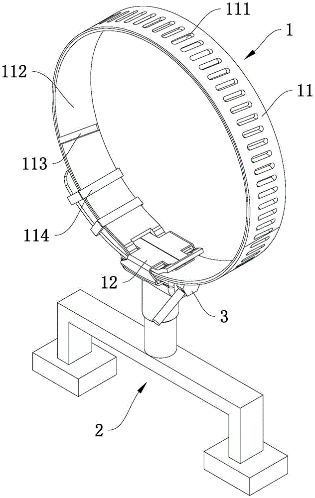
Fig. 1 is a schematic view of the overall structure of embodiment 1.
Fig. 2 is a schematic diagram of the explosive structure of example 1.
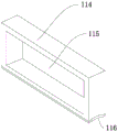
Fig. 3 is a schematic structural view of the positioning buckle in embodiment 1.
Fig. 4 is a partial structural view of embodiment 2.
In the figure, 1, fixing the assembly; 11. a fixing strip; 111. adjusting the chute; 112. a shock pad; 113. embedding the groove; 114. positioning buckles; 115. a positioning groove; 116. a flexible pad; 12. a fixing buckle; 121. positioning the through hole; 122. a mounting ring; 123. mounting a through hole; 2. a fixed seat; 21. positioning a rod; 22. a cross bar; 23. a support bar; 24. supporting legs; 241. positioning a plate; 25. a positioning member; 3. adjusting a rod; 31. adjusting the screw thread; 32. mounting holes; 33. an extension rod.
Detailed Description
The present invention will be described in further detail with reference to the accompanying drawings.
In the case of the example 1, the following examples are given,
referring to fig. 1, a pipe mounting bracket includes a fixing assembly 1, a fixing base 2, and an adjusting lever 3.
The fixing assembly 1 comprises a fixing strip 11, fixing buckles 12 positioned at the bottom of the fixing strip 11 and fixing buckles 12 arranged at intervals along the length direction of the fixing strip 11.
Referring to fig. 1 and 2, the fixing buckle 12 is located below the fixing strip 11, and a positioning through hole 121 horizontally penetrating through the fixing buckle 12 is formed in a side portion of the fixing buckle 12. One end of the fixing strip 11 is connected with the fixing buckle 12, the other end of the fixing strip 11 penetrates through a positioning through hole 121 in the fixing buckle 12, and a plurality of adjusting chutes 111 are obliquely formed in the bottom of the fixing strip 11.
Adjust pole 3 horizontal hinge and install on the stationary dog 12, be provided with on adjusting the pole 3 and adjust screw thread 31, adjust screw thread 31 and be the heliciform and set up in the lateral wall of adjusting pole 3, adjust the top embedding of screw thread 31 and be located the regulation chute 111 on the fixed strip 11, in this embodiment, the cross-section of adjusting screw thread 31 is trapezoidal. At least three mounting holes 32 are formed in the circumferential direction of the side wall of the adjusting rod 3 at even intervals, and an extension rod 33 is inserted into the mounting holes 32.
Referring to fig. 1 and 3, the inner wall of fixed strip 11 is provided with shock pad 112, be equipped with a plurality of embedding recesses 113 along its length direction interval on the shock pad 112, the location is detained 114 and is provided with threely along the length direction interval of fixed strip 11, the location is detained 114 and is cyclic annular setting, the lateral wall level of location knot 114 is seted up the positioning groove 115 that supplies the fixed strip 11 tip to pass, the complete joint in embedding recess 113 in bottom of location knot 114, the location is detained 114 and is provided with flexible pad towards one side of pipeline, the lateral wall and the laminating of pipeline outer wall of flexible pad. In this embodiment, the number of the positioning buckles 114 is two, and when the length of the fixing strip 11 extending out of the fixing buckle 12 is longer, the number of the positioning buckles 114 can be increased appropriately.
Referring to fig. 2, a mounting ring 122 is disposed at the bottom of the fixing buckle 12, a mounting through hole 123 is disposed at the bottom of the mounting ring 122, the fixing base 2 has a positioning rod 21 threadedly mounted in the mounting through hole 123, a cross rod 22 mounted at the bottom of the positioning rod 21, and supporting rods 23 disposed at two ends of the cross rod 22, and a positioning plate 24 is disposed at the bottom of the supporting rods. In this embodiment, the cross bar 22 is perpendicular to the positioning rod 21, the supporting rod 23 is parallel to the positioning rod 21, and the positioning plate 24 is welded to the supporting rod 23.
In the case of the example 2, the following examples are given,
in this embodiment, the structure is the same as that of embodiment 1 except for the structure of the fixing base 2.
The fixing base 2 further has a positioning element 25 installed at the bottom of the positioning rod 21, in this embodiment, the positioning element 25 is in an inverted trapezoid shape, and the positioning element 25 is integrally embedded in the ground.
The use principle of the above embodiment is as follows: during the installation, the pipeline joint is in fixed strip 11, insert the fixed strip 11 in the positioning hole 121 on the fixed knot 12 afterwards, rotation regulation pole 3, make the regulation screw 31 that is located on adjusting pole 3 drive the one end orientation that fixed strip 11 is not connected with fixed knot 12 and keep away from the one side motion of fixed knot 12, thereby realize the locking to the pipeline, the lateral wall of fixed strip 11 and the lateral wall laminating of pipeline, the area of contact between pipeline and fixed strip 11 has been increased, fixed strip 11 has been reduced to the pressure of pipeline, the frictional force between fixed strip 11 and the pipeline has been increased, make the bonding strength between pipeline and the fixed strip 11 higher, and reduced the pipeline and received the probability that fixed strip 11 extrudees and take place the deformation, the life of pipeline has been promoted to a certain extent.
The embodiment of this specific implementation mode is the preferred embodiment of the present invention, not limit according to this the utility model discloses a protection scope, so: all equivalent changes made according to the structure, shape and principle of the utility model are covered within the protection scope of the utility model.