CN212455673U - Water tap - Google Patents
Water tap Download PDFInfo
- Publication number
- CN212455673U CN212455673U CN202020981327.2U CN202020981327U CN212455673U CN 212455673 U CN212455673 U CN 212455673U CN 202020981327 U CN202020981327 U CN 202020981327U CN 212455673 U CN212455673 U CN 212455673U
- Authority
- CN
- China
- Prior art keywords
- water
- cavity
- channel
- communicated
- outlet hole
- Prior art date
- Legal status (The legal status is an assumption and is not a legal conclusion. Google has not performed a legal analysis and makes no representation as to the accuracy of the status listed.)
- Expired - Fee Related
Links
- XLYOFNOQVPJJNP-UHFFFAOYSA-N water Substances O XLYOFNOQVPJJNP-UHFFFAOYSA-N 0.000 title claims abstract description 166
- 230000009286 beneficial effect Effects 0.000 description 1
- 239000007921 spray Substances 0.000 description 1
Images


Landscapes
- Domestic Plumbing Installations (AREA)
- Multiple-Way Valves (AREA)
Abstract
The utility model discloses a water faucet, its characterized in that: comprises a first cavity and a second cavity; the first cavity is connected with the second cavity through a main pipe; a water distribution cavity is arranged inside the first cavity, and a water mixing cavity is arranged inside the second cavity; cold and hot water is introduced into the water mixing cavity through a first water inlet arranged on the first cavity and a second water inlet arranged on the second cavity, and the cold and hot water is mixed in the water mixing cavity and then is sent into the water dividing cavity; a first water outlet hole, a second water outlet hole, a third water outlet hole, a fourth water outlet hole and a water inlet hole are formed in the water diversion cavity; a first water channel, a second water channel, a third water channel and a fourth water channel are arranged in the main pipe; because the device is provided with the water mixing cavity in the second part and the cold and hot water is uniformly mixed and discharged in sequence through the water mixing cavity, the device can not only finish the uniform mixing of the cold and hot water without external equipment.
Description
Technical Field
The utility model relates to a hardware fitting technical field specifically is a tap.
Background
Traditional shunt valve function singleness only is equipped with the outlet pipe of connecting the gondola water faucet moreover, and the user can only take from the gondola water faucet when getting water, perhaps installs the valve in addition, and is troublesome to use. In addition, when a bathroom is cleaned, some corners need to be washed by strong water flow, the water can be washed clean, the water outlet of a common faucet is not strong enough, the requirement cannot be met, a spray gun is additionally installed by a user, a bathtub or a multifunctional shower is arranged in some bathrooms, a plurality of valves need to be correspondingly installed, and the operation is complex and troublesome.
In view of the above problems, there is a solution, for example, patent No. CN 207394031U, which requires mixing hot and cold water during sanitary use, but the mixing of hot and cold water is actually performed outside the faucet, and therefore at least one auxiliary device is required to mix hot and cold water.
SUMMERY OF THE UTILITY MODEL
An object of the utility model is to provide a tap to solve the problem that proposes among the above-mentioned background art.
In order to achieve the above object, the utility model provides a following technical scheme: a faucet comprises a first cavity and a second cavity; the first cavity is connected with the second cavity through a main pipe; a water distribution cavity is arranged inside the first cavity, a water mixing cavity is arranged inside the second cavity, and a water mixing valve is arranged in the water mixing cavity; cold and hot water is introduced into the water mixing cavity through a first water inlet arranged on the first cavity and a second water inlet arranged on the second cavity, and the cold and hot water is mixed in the water mixing cavity and then is sent into the water dividing cavity; a first water outlet hole, a second water outlet hole, a third water outlet hole, a fourth water outlet hole and a water inlet hole are formed in the water diversion cavity; a first water channel, a second water channel, a third water channel and a fourth water channel are arranged in the main pipe; one end of the first water channel is communicated with the first water inlet, and the other end of the first water channel is communicated with the water mixing cavity; one end of the second water channel is communicated with the first water outlet hole, and the other end of the second water channel is communicated with a water outlet end arranged outside the second cavity; the third water channel is communicated with the water distribution cavity and the water mixing cavity, wherein the third water channel is communicated with the water distribution cavity through the water inlet; one end of the fourth water channel is connected and communicated with the second water outlet hole, and the other end of the fourth water channel is connected and communicated with a water outlet arranged outside the main pipe; a fifth water channel is further arranged on the water distribution cavity, and the fifth water channel is communicated with the third water outlet hole; and the fourth water outlet hole is communicated with a water outlet pipe arranged outside the first cavity in a connecting way.
As the utility model discloses a preferred technical scheme: the water diversion cavity and the interior of the water mixing cavity are both provided with water diversion switches.
Adopt above-mentioned technical scheme, the beneficial effects of the utility model are that: because the device is provided with the water mixing cavity in the second part and the cold and hot water is uniformly mixed and discharged in sequence through the water mixing cavity, the device can not only finish the uniform mixing of the cold and hot water without external equipment.
Drawings
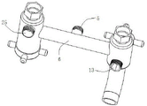
FIG. 1 is a schematic view of the main structure of the present invention;
FIG. 2 is another side view of FIG. 1;
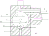
fig. 3 is a schematic sectional structure of the present invention;
fig. 4 is a partially enlarged schematic view of the first part of the present invention.
In the figure: 1. a first cavity; 2. a water diversion cavity; 3. a first water inlet; 4. a fourth water channel; 5. a water outlet; 6. a header pipe; 7. a third water channel; 8. a second water channel; 9. a first water channel; 10. A second cavity; 11. a second water inlet; 12. a water mixing cavity; 20. a first water outlet; 21. a second water outlet; 22. a water inlet hole; 23. a third water outlet; 24. a fourth water outlet; 25. a water outlet pipe; 26. a fifth flume.
Detailed Description
Reference will now be made in detail to embodiments of the present invention, examples of which are illustrated in the accompanying drawings, wherein like reference numerals refer to the same or similar elements or elements having the same or similar function throughout. The embodiments described below with reference to the drawings are exemplary and intended to be used for explaining the present invention, and should not be construed as limiting the present invention. In the description of the present invention, it should be understood that the terms "upper", "lower", "front", "upper surface", etc. indicate the orientation or positional relationship based on the orientation or positional relationship shown in the drawings, and are only for convenience of description and simplification of description, but do not indicate or imply that the device or element referred to must have a specific orientation, be constructed in a specific orientation, and be operated, and thus should not be construed as limiting the present invention. In the present invention, unless otherwise expressly stated or limited, the terms "mounted," "connected," and "fixed" are to be construed broadly and may, for example, be fixedly connected, detachably connected, or integrally formed; can be mechanically connected, electrically connected or can communicate with each other; either directly or indirectly through intervening media, either internally or in any other relationship. The specific meaning of the above terms in the present invention can be understood according to specific situations by those skilled in the art.
Referring to fig. 1-4, the present invention provides an embodiment: a faucet comprises a first cavity 1 and a second cavity 10; the first cavity 1 is connected with the second cavity 10 through a header pipe 6; a water diversion cavity 2 is arranged inside the first cavity 1, a water mixing cavity 12 is arranged inside the second cavity 10, and a water mixing valve is arranged in the water mixing cavity 12; cold and hot water is introduced into the water mixing cavity 12 through a first water inlet 3 arranged on the first cavity 1 and a second water inlet 11 arranged on the second cavity 10, and is mixed in the water mixing cavity 12 and then is sent into the water diversion cavity 2; a first water outlet hole 20, a second water outlet hole 21, a third water outlet hole 23, a fourth water outlet hole 24 and a water inlet hole 22 are formed in the water distribution cavity 2; a first water channel 9, a second water channel 8, a third water channel 7 and a fourth water channel 4 are arranged in the header pipe 6; one end of the first water channel 9 is communicated with the first water inlet 3, and the other end of the first water channel is communicated with the water mixing cavity 12; one end of the second water channel 8 is connected and communicated with the first water outlet hole 20, and the other end of the second water channel is connected and communicated with a water outlet end 13 arranged outside the second cavity 10; the third water channel 7 is communicated with the water diversion cavity 2 and the water mixing cavity 12, wherein the third water channel 7 is communicated with the water diversion cavity 2 through the water inlet hole 22; one end of the fourth water channel 4 is connected and communicated with the second water outlet hole 21, and the other end of the fourth water channel is connected and communicated with a water outlet 5 arranged outside the header pipe 6; a fifth water channel 26 is further arranged on the water distribution cavity 2, wherein the fifth water channel 26 is connected and communicated with the third water outlet 23; the fourth water outlet hole 24 is connected and communicated with a water outlet pipe 25 arranged outside the first cavity 1, and cold water and hot water respectively enter a water mixing valve core of the water mixing cavity 12, are mixed and adjusted in temperature by controlling the ratio of the cold water to the hot water through the water mixing valve core, and then flow out through a water outlet hole, wherein the water mixing valve is JODS/Jones, model: 1705/1706.
Further, divide the water cavity 2 and the inside of mixing water cavity 12 all installs the water diversion switch, and wherein the model of water diversion switch is QT145, because the water diversion switch of this model, can be completely corresponding with the inside hole in this application water cavity 2, and then be convenient for control each play water part through this valve in proper order and go out water.
The water dividing valve has the general working principle that the water dividing valve generally comprises a fixed plate and a movable plate, wherein the fixed plate is fixed at the lower end of a valve seat and is fixed and immobile;
the stator is provided with two water inlet holes which are respectively corresponding to the cold water hole and the hot water hole on the water mixing cavity 12;
then, the movable plate is also provided with two holes corresponding to the fixed plate, the two holes are corresponding in size, and the size of the overlapped hole of the movable plate and the size of the overlapped hole of the fixed plate are changed by rotating the movable plate, so that the water diversion function is realized.
Claims (2)
1. A faucet, characterized in that: comprises a first cavity (1) and a second cavity (10); the first cavity (1) is connected with the second cavity (10) through a header pipe (6);
a water distribution cavity (2) is arranged inside the first cavity (1), a water mixing cavity (12) is arranged inside the second cavity (10), and a water mixing valve is arranged in the water mixing cavity (12);
cold and hot water is introduced into the water mixing cavity (12) through a first water inlet (3) arranged on the first cavity (1) and a second water inlet (11) arranged on the second cavity (10), and is mixed in the water mixing cavity (12) and then is sent into the water distribution cavity (2);
a first water outlet hole (20), a second water outlet hole (21), a third water outlet hole (23), a fourth water outlet hole (24) and a water inlet hole (22) are formed in the water distribution cavity (2);
a first water channel (9), a second water channel (8), a third water channel (7) and a fourth water channel (4) are arranged in the main pipe (6);
one end of the first water channel (9) is communicated with the first water inlet (3), and the other end of the first water channel is communicated with the water mixing cavity (12);
one end of the second water channel (8) is communicated with the first water outlet hole (20), and the other end of the second water channel is communicated with a water outlet end (13) arranged outside the second cavity (10);
the third water channel (7) is communicated with the water diversion cavity (2) and the water mixing cavity (12), wherein the third water channel (7) is communicated with the water diversion cavity (2) through the water inlet hole (22);
one end of the fourth water channel (4) is connected and communicated with the second water outlet hole (21), and the other end of the fourth water channel is connected and communicated with a water outlet (5) arranged outside the header pipe (6);
a fifth water channel (26) is further arranged on the water distribution cavity (2), wherein the fifth water channel (26) is communicated with the third water outlet hole (23);
the fourth water outlet hole (24) is communicated with a water outlet pipe (25) arranged outside the first cavity (1).
2. A faucet as set forth in claim 1, wherein: and a water distribution switch is arranged in the water distribution cavity (2).
Priority Applications (1)
| Application Number | Priority Date | Filing Date | Title |
|---|---|---|---|
| CN202020981327.2U CN212455673U (en) | 2020-06-02 | 2020-06-02 | Water tap |
Applications Claiming Priority (1)
| Application Number | Priority Date | Filing Date | Title |
|---|---|---|---|
| CN202020981327.2U CN212455673U (en) | 2020-06-02 | 2020-06-02 | Water tap |
Publications (1)
| Publication Number | Publication Date |
|---|---|
| CN212455673U true CN212455673U (en) | 2021-02-02 |
Family
ID=74478343
Family Applications (1)
| Application Number | Title | Priority Date | Filing Date |
|---|---|---|---|
| CN202020981327.2U Expired - Fee Related CN212455673U (en) | 2020-06-02 | 2020-06-02 | Water tap |
Country Status (1)
| Country | Link |
|---|---|
| CN (1) | CN212455673U (en) |
-
2020
- 2020-06-02 CN CN202020981327.2U patent/CN212455673U/en not_active Expired - Fee Related
Similar Documents
| Publication | Publication Date | Title |
|---|---|---|
| CN213204352U (en) | Closestool washes waterway structure and closestool | |
| CN217301705U (en) | A five-function shower faucet structure | |
| CN208281561U (en) | A kind of Multifunctional faucet | |
| CN209196172U (en) | A kind of tap valve core | |
| CN220377429U (en) | Concealed water path system for shower head | |
| CN218845193U (en) | Faucet integrating cold and hot tap water and cold and hot purified water | |
| CN218267366U (en) | A temperature control valve and a multifunctional body cleaner using the same | |
| CN215059689U (en) | Dual-function washbasin faucet | |
| CN211756065U (en) | Water outlet device with multiple water outlet spray | |
| CN211175485U (en) | Mixed water outlet faucet assembly | |
| CN115628307A (en) | A buried wall concealed waterway system for exposed showers | |
| CN222836329U (en) | Multifunctional water tap | |
| CN218000496U (en) | multifunction faucet | |
| CN220060622U (en) | Kitchen tap with single handle, double control and double water outlet | |
| CN221654159U (en) | Mechanical toilet bowl cover body | |
| CN221168029U (en) | Concealed shower main body structure | |
| CN220910545U (en) | Kitchen tap with water purification function | |
| CN209876028U (en) | Filtering water switching faucet | |
| CN224107704U (en) | A shower head body water channel structure | |
| CN220266735U (en) | Extensible embedded water path system | |
| CN223875262U (en) | A type of overhead shower head with adjustable flow rate | |
| CN220523354U (en) | Tap switch of shower head | |
| CN223019554U (en) | Pull tap with water purification goes out water mode | |
| CN224260956U (en) | Tap water distribution core and shower tap manufactured by using same | |
| CN224161151U (en) | A multi-functional pull-out head and basin faucet device |
Legal Events
| Date | Code | Title | Description |
|---|---|---|---|
| GR01 | Patent grant | ||
| GR01 | Patent grant | ||
| CF01 | Termination of patent right due to non-payment of annual fee |
Granted publication date: 20210202 |
|
| CF01 | Termination of patent right due to non-payment of annual fee |