CN212451400U - Compound microbial fermentation jar convenient to wash - Google Patents
Compound microbial fermentation jar convenient to wash Download PDFInfo
- Publication number
- CN212451400U CN212451400U CN202020638264.0U CN202020638264U CN212451400U CN 212451400 U CN212451400 U CN 212451400U CN 202020638264 U CN202020638264 U CN 202020638264U CN 212451400 U CN212451400 U CN 212451400U
- Authority
- CN
- China
- Prior art keywords
- fixedly connected
- tank
- cover
- pipe
- tank body
- Prior art date
- Legal status (The legal status is an assumption and is not a legal conclusion. Google has not performed a legal analysis and makes no representation as to the accuracy of the status listed.)
- Expired - Fee Related
Links
Images


Abstract
The utility model discloses a compound microbial fermentation jar convenient to wash, including a jar body, cover, feeding tube, row's material pipe, control valve, landing leg and wiper mechanism, the top of jar body is provided with the cover, the right side fixedly connected with feeding tube at cover top, the material pipe is arranged to the midpoint department fixedly connected with of jar body bottom, the left side fixed mounting who arranges the material pipe has the control valve, the equal fixedly connected with landing leg in four corners department of jar body bottom, the midpoint department at cover top is provided with wiper mechanism, wiper mechanism includes driving motor, fixed connection between driving motor and the cover. The utility model discloses a jar body, cover, throw material pipe, arrange material pipe, control valve, landing leg and wiper mechanism and mutually support, played the abluent effect of being convenient for, the cleaning process need not artifical handheld cleaning equipment and washs, easy operation, labour saving and time saving has greatly reduced staff's intensity of labour, and the cleaning performance is good, simple structure, and the practicality is strong, is worth promoting.
Description
Technical Field
The utility model relates to a microbial fermentation tank technical field specifically is a compound microbial fermentation jar convenient to wash.
Background
Common fermentors are classified as solid fermentors and liquid fermentors. The fermentation tank is divided into a seed tank and a fermentation tank according to different volumes and purposes. The fermentation tank is classified into a vented fermentation tank and an anaerobic fermentation tank according to the aerobic type. The stirring device of the fermentation tank comprises mechanical stirring and non-mechanical stirring. The stirring device for ventilation fermentation comprises a motor, a transmission device, a stirring shaft, a shaft sealing device and a stirring paddle. The purpose of mechanical agitation is to rapidly disperse the bubbles and mix the added materials. One paddle is sometimes contradictory to achieve both objectives. For example, a large diameter agitator and low speed operation are required to achieve mixing, while multiple blades, small diameter and high speed are required to improve the dispersing bubble effect. The input power of the motor is determined by the form of the stirring paddle and other fermentation tank components. 4 baffles are often installed in the fermenter to increase mixing, heat transfer and mass transfer efficiency. In aerobic submerged fermenters, compressed air from a sterile air system is injected into the fermentor through an air distributor, which has a single-bore tubular configuration and a multi-bore tubular configuration. The installation method is different, and the installation method is generally installed below the lowest first stirrer, but all the installation methods need to be taken to prevent the air holes from being blocked by thalli or solid particles in the fermentation liquor. Some air distributors are provided with water discharging structures, so that no fermentation liquor remains in the pipe after the tank is placed. The aeration speed is based on the requirement of microbial fermentation, and the dissolved oxygen is above the critical oxygen depth. Depending on the design and operation of the system. The upper limit of the air flow rate is the speed at which the air can be effectively dispersed by the paddles, depending on the paddle type and rotational speed. The microbial fermentation tank needs to be cleaned regularly when in use.
At present, common microbial fermentation tank is not convenient for wash, and the cleaning process needs artifical handheld cleaning equipment to wash, and complex operation wastes time and energy, has greatly increased staff's intensity of labour, and washs thoroughly insufficiently to influence microbial fermentation's quality, brought very big inconvenience for the producer.
SUMMERY OF THE UTILITY MODEL
An object of the utility model is to provide a compound microbial fermentation jar convenient to wash to solve the problem of proposing among the above-mentioned background art.
In order to achieve the above object, the utility model provides a following technical scheme: a composite microbial fermentation tank convenient to clean comprises a tank body, a tank cover, a feeding pipe, a discharging pipe, a control valve, supporting legs and a cleaning mechanism, wherein the tank cover is arranged at the top of the tank body;
the cleaning mechanism comprises a driving motor, the driving motor is fixedly connected with the tank cover, a driving rotating shaft is fixedly connected with an output shaft of the driving motor, the bottom of the driving rotating shaft penetrates through the tank cover and extends to a first scraper plate of the internal fixedly connected with, the surface of the driving rotating shaft is fixedly connected with a stirring paddle in the tank body, two fixing rods are symmetrically arranged on the right side of the driving rotating shaft, the right ends of the two fixing rods are fixedly connected with a second scraper plate, the top of the inner wall of the tank body is fixedly connected with a ring pipe, the bottom of the ring pipe is fixedly connected with a high-pressure nozzle, the left side of the ring pipe is fixedly connected with a water inlet pipe, and the left end of the water.
Preferably, the left side of the top of the tank cover is fixedly connected with an air inlet pipe, and the bottom of the left side of the tank body is fixedly connected with a heating block.
Preferably, the discharge pipe is communicated with the tank body.
Preferably, the fixing rod is fixedly connected with the driving rotating shaft.
Preferably, the water inlet pipe is communicated with the ring pipe.
Compared with the prior art, the beneficial effects of the utility model are as follows:
the utility model discloses a jar body, cover, throw material pipe, arrange material pipe, control valve, landing leg and wiper mechanism and mutually support, played the abluent effect of being convenient for, the cleaning process need not artifical handheld cleaning equipment and washs, easy operation, labour saving and time saving has greatly reduced staff's intensity of labour, and the cleaning performance is good, simple structure, and the practicality is strong, is worth promoting.
Drawings
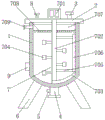
FIG. 1 is a structural section view in elevation of the present invention;
FIG. 2 is a schematic structural diagram of a top view of a can lid according to the present invention;
fig. 3 is a schematic structural view of a bottom view of the grommet according to the present invention;
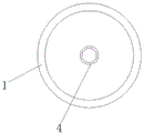
fig. 4 is a schematic structural diagram of a top view of the tank body of the present invention.
In the figure: 1 tank body, 2 tank covers, 3 feeding pipes, 4 discharging pipes, 5 control valves, 6 supporting legs, 7 cleaning mechanisms, 701 driving motors, 702 driving rotating shafts, 703 first scraping plates, 704 stirring paddles, 705 fixing rods, 706 second scraping plates, 707 ring pipes, 708 high-pressure spray heads, 709 water inlet pipes, 8 air inlet pipes and 9 heating blocks.
Detailed Description
The technical solutions in the embodiments of the present invention will be described clearly and completely with reference to the accompanying drawings in the embodiments of the present invention, and it is obvious that the described embodiments are only some embodiments of the present invention, not all embodiments. Based on the embodiments in the present invention, all other embodiments obtained by a person skilled in the art without creative work belong to the protection scope of the present invention.
Referring to fig. 1-4, a compound microbial fermentation tank convenient to clean comprises a tank body 1, a tank cover 2, a feeding pipe 3, a discharging pipe 4, a control valve 5, support legs 6 and a cleaning mechanism 7, wherein the tank cover 2 is arranged at the top of the tank body 1, the feeding pipe 3 is fixedly connected to the right side of the top of the tank cover 2, the discharging pipe 4 is fixedly connected to the midpoint of the bottom of the tank body 1, the discharging pipe 4 is communicated with the tank body 1, the control valve 5 is fixedly arranged at the left side of the discharging pipe 4, the support legs 6 are fixedly connected to four corners of the bottom of the tank body 1, the cleaning mechanism 7 is arranged at the midpoint of the top of the tank cover 2, an air inlet pipe 8 is fixedly connected to the left side of the top of the.
The cleaning mechanism 7 comprises a driving motor 701, the driving motor 701 is fixedly connected with the tank cover 2, a driving rotating shaft 702 is fixedly connected to an output shaft of the driving motor 701, the bottom of the driving rotating shaft 702 penetrates through the tank cover 2 and extends to a first scraper 703 fixedly connected to the inside of the tank cover, a stirring paddle 704 is fixedly connected to the surface of the driving rotating shaft 702 and is located inside the tank body 1, two fixing rods 705 are symmetrically arranged on the right side of the driving rotating shaft 702, the right ends of the two fixing rods 705 are fixedly connected through a second scraper 706, the fixing rods 705 are fixedly connected with the driving rotating shaft 702, a ring pipe 707 is fixedly connected to the top of the inner wall of the tank body 1, a high-pressure spray head 708 is fixedly connected to the bottom of the ring pipe 707, a water inlet pipe 709 is fixedly connected to the left side of the ring pipe 707.
When the cleaning device is used, when the interior of the tank body 1 needs to be cleaned, a user connects the water inlet pipe 709 with an external water pump, the water pump pumps water to the interior of the circular pipe 707, the high-pressure spray head 708 sprays water to wash the inner wall of the tank body 1, the driving motor 701 drives the driving rotating shaft 702, the first scraper 703, the fixed rod 705 and the second scraper 706 to rotate, so that the first scraper 703 and the second scraper 706 clean the inner wall of the tank body 1 in an all-dimensional manner, and impurities on the inner wall of the tank body 1 are washed clean under the action of water pressure and water flow, and sewage is discharged from the discharge pipe 4.
The utility model discloses the electrical components who appears in all are connected with external master controller electricity to the master controller can be for the computer etc. to play the conventional known equipment of control, the utility model discloses in circuit and control that relate to be prior art, do not carry out too much repetitious description here.
Although embodiments of the present invention have been shown and described, it will be appreciated by those skilled in the art that changes, modifications, substitutions and alterations can be made in these embodiments without departing from the principles and spirit of the invention, the scope of which is defined in the appended claims and their equivalents.
Claims (5)
1. The utility model provides a compound microbial fermentation jar convenient to wash, includes jar body (1), cover (2), throws material pipe (3), arranges material pipe (4), control valve (5), landing leg (6) and wiper mechanism (7), its characterized in that: the tank is characterized in that a tank cover (2) is arranged at the top of the tank body (1), a feeding pipe (3) is fixedly connected to the right side of the top of the tank cover (2), a discharging pipe (4) is fixedly connected to the middle point of the bottom of the tank body (1), a control valve (5) is fixedly installed on the left side of the discharging pipe (4), supporting legs (6) are fixedly connected to four corners of the bottom of the tank body (1), and a cleaning mechanism (7) is arranged at the middle point of the top of the tank cover (2);
the cleaning mechanism (7) comprises a driving motor (701), the driving motor (701) is fixedly connected with the tank cover (2), a driving rotating shaft (702) is fixedly connected to an output shaft of the driving motor (701), the bottom of the driving rotating shaft (702) penetrates through the tank cover (2) and extends to the interior of the tank cover to be fixedly connected with a first scraper (703), stirring paddles (704) are fixedly connected to the surface of the driving rotating shaft (702) and are located in the tank body (1), two fixing rods (705) are symmetrically arranged on the right side of the driving rotating shaft (702), the right ends of the two fixing rods (705) are fixedly connected through a second scraper (706), a ring pipe (707) is fixedly connected to the top of the inner wall of the tank body (1), a high-pressure spray head (708) is fixedly connected to the bottom of the ring pipe (707), and a water inlet pipe (709) is fixedly connected, the left end of the water inlet pipe (709) penetrates through the tank body (1) and extends to the outside of the tank body.
2. The composite microbial fermentation tank convenient for cleaning as claimed in claim 1, wherein: the left side fixedly connected with intake pipe (8) at cover (2) top, jar body (1) left bottom fixedly connected with heating block (9).
3. The composite microbial fermentation tank convenient for cleaning as claimed in claim 1, wherein: the discharge pipe (4) is communicated with the tank body (1).
4. The composite microbial fermentation tank convenient for cleaning as claimed in claim 1, wherein: the fixed rod (705) is fixedly connected with the driving rotating shaft (702).
5. The composite microbial fermentation tank convenient for cleaning as claimed in claim 1, wherein: the water inlet pipe (709) is communicated with the ring pipe (707).
Priority Applications (1)
| Application Number | Priority Date | Filing Date | Title |
|---|---|---|---|
| CN202020638264.0U CN212451400U (en) | 2020-04-24 | 2020-04-24 | Compound microbial fermentation jar convenient to wash |
Applications Claiming Priority (1)
| Application Number | Priority Date | Filing Date | Title |
|---|---|---|---|
| CN202020638264.0U CN212451400U (en) | 2020-04-24 | 2020-04-24 | Compound microbial fermentation jar convenient to wash |
Publications (1)
| Publication Number | Publication Date |
|---|---|
| CN212451400U true CN212451400U (en) | 2021-02-02 |
Family
ID=74469190
Family Applications (1)
| Application Number | Title | Priority Date | Filing Date |
|---|---|---|---|
| CN202020638264.0U Expired - Fee Related CN212451400U (en) | 2020-04-24 | 2020-04-24 | Compound microbial fermentation jar convenient to wash |
Country Status (1)
| Country | Link |
|---|---|
| CN (1) | CN212451400U (en) |
Cited By (3)
| Publication number | Priority date | Publication date | Assignee | Title |
|---|---|---|---|---|
| CN112868809A (en) * | 2021-02-05 | 2021-06-01 | 明富(上海)健康科技有限公司 | Processing method of fresh cheese beneficial to gastrointestinal health |
| CN113171744A (en) * | 2021-06-01 | 2021-07-27 | 广东佳纳能源科技有限公司 | Precursor reaction device and reaction method |
| CN114958521A (en) * | 2022-06-10 | 2022-08-30 | 疏勒县阿纳石榴干红酒业有限公司 | Red date wine fermentation cylinder convenient to slag discharging |
-
2020
- 2020-04-24 CN CN202020638264.0U patent/CN212451400U/en not_active Expired - Fee Related
Cited By (3)
| Publication number | Priority date | Publication date | Assignee | Title |
|---|---|---|---|---|
| CN112868809A (en) * | 2021-02-05 | 2021-06-01 | 明富(上海)健康科技有限公司 | Processing method of fresh cheese beneficial to gastrointestinal health |
| CN113171744A (en) * | 2021-06-01 | 2021-07-27 | 广东佳纳能源科技有限公司 | Precursor reaction device and reaction method |
| CN114958521A (en) * | 2022-06-10 | 2022-08-30 | 疏勒县阿纳石榴干红酒业有限公司 | Red date wine fermentation cylinder convenient to slag discharging |
Similar Documents
| Publication | Publication Date | Title |
|---|---|---|
| CN212451400U (en) | Compound microbial fermentation jar convenient to wash | |
| CN209721623U (en) | A kind of sewage treatment chemicals dosing plant | |
| CN210117378U (en) | Microbial fermentation jar convenient to wash | |
| CN105820943B (en) | A kind of multi-stage gas-liquid joint stirring Venturi tube-CSTR reaction units | |
| CN201376917Y (en) | Solid liquid flow mixing device of anaerobic reactor | |
| CN101508486B (en) | Anaerobic reactor tridimensional flow agitating apparatus | |
| CN206351024U (en) | A kind of adhesive reaction equipment with twocouese agitating device | |
| CN210367662U (en) | Microbial inoculum fermentation cylinder | |
| CN217324056U (en) | Microbial liquid fermentation tank capable of being heated uniformly | |
| CN213202769U (en) | High-efficient fermenting installation of municipal administration mud | |
| CN214486912U (en) | Epoxy curing agent retort | |
| CN206287343U (en) | It is a kind of to be easy to the efficient concrete batch plant for mixing | |
| CN210103924U (en) | Gas-liquid mixing device of aerobic fermentation tank | |
| CN205062077U (en) | Gas -liquid jointly stirs venturi - entirely and mixes anaerobic digestion reactor | |
| CN201581073U (en) | Full-automatic two-step multi-stage fermentation methane tank | |
| CN213141982U (en) | Large-scale fermentation equipment | |
| CN211620055U (en) | Low-energy-consumption aeration tank for stirring by utilizing jet air | |
| CN211813708U (en) | Aeration tank capable of cutting bubbles | |
| CN203639450U (en) | Self-suction fermentation tank | |
| CN212669665U (en) | Mechanical and liquid spraying combined stirring device matched with anaerobic fermentation system | |
| CN218491714U (en) | Stirring system of biochemical fermentation tank | |
| CN220079052U (en) | Air distributor and fermentation tank using same | |
| CN208912077U (en) | A kind of gutter oil prepares the agitator tank of biological liquid fuel | |
| CN216337607U (en) | But fermentation tank body is used in microbial fermentation production of self-cleaning disinfection | |
| CN220495649U (en) | Prevent dissolving medicine of precipitation and put in agitating unit |
Legal Events
| Date | Code | Title | Description |
|---|---|---|---|
| GR01 | Patent grant | ||
| GR01 | Patent grant | ||
| CF01 | Termination of patent right due to non-payment of annual fee |
Granted publication date: 20210202 |
|
| CF01 | Termination of patent right due to non-payment of annual fee |