Quick connection structure of low-voltage short-circuit wire
Technical Field
The utility model belongs to power supply unit and accessory equipment field especially relate to low pressure circuit technique, concretely relates to low pressure short-circuit connection's fast tying constructs.
Background
The low-voltage line comprises a low-voltage overhead line, a low-voltage overhead insulated line, a low-voltage cable line and an indoor distribution line, is used for directly transmitting electric energy to low-voltage electric equipment, and is an important component of a low-voltage distribution system. The low-voltage line can be accessed from a public low-voltage distribution network and is led out through a low-voltage distribution room; and the low-voltage power distribution device can also be led out from a transformer substation chamber of a user.
Patent document No. CN206922068U discloses a connection terminal, which includes a first housing, a second housing, an elastic piece, a first current bar and a second current bar, wherein the first housing and the second housing are connected by screw threads, one end of the elastic piece is inserted into the first housing, the other end of the elastic piece extends into the second housing, the first current bar and the second current bar are respectively inserted into the first housing and the second housing, and the first current bar and the second current bar are respectively and correspondingly connected to two ends of the elastic piece. The utility model provides a threaded connection between first casing and the second casing, first casing are concatenation formula structure, and the flexure strip is pegged graft in first casing, and is located first casing through spacing muscle, when extracting first electric current strip and second electric current strip from the flexure strip, the flexure strip can not transform the position along with breaking away from of electric current strip, and the fastening is effectual, and first electric current strip and second electric current strip are pegged graft on the flexure strip, the loading and unloading of being convenient for.
The applicant finds that when the wire is pulled by external force, the wire connection mechanism is easy to drop or break the connection winding of the wire, and the operation stability of the power line is affected.
The applicant has therefore proposed an improved wiring mechanism.
Disclosure of Invention
The utility model aims at solving the technical problem that the wire connected through the wiring mechanism meets the unintentional external force at both ends and pulls or the intentional damage formula external force pulls, causes breaking away from and damaging of junction easily, influences the stability of power line operation.
In order to achieve the above purpose, the utility model discloses a following technical scheme realizes:
a quick connection structure of a low-voltage short connecting wire comprises a connecting terminal, a first shell and a second shell; one end of the first shell and one end of the second shell are connecting parts, and the other end of the first shell and the other end of the second shell are free ends; the first shell and the second shell form a shell component with a cavity structure after being connected at the connecting part, and a connecting terminal is arranged in the cavity structure and positioned at the connecting part of the first shell and the second shell; the free ends of the first shell and the second shell are provided with wire channels, and two ends of the wiring terminal are provided with wire slots; the connecting part of the first shell and the second shell is a structure which can be separated or folded and is fastened after being folded.
And wire fastening mechanisms are arranged at the wire slots at the two ends of the wiring terminal and used for fastening the wires after the wires are inserted into the wire slots.
The wire fastening mechanism comprises a bolt perpendicular to the wire slot, the bolt is in threaded connection with an opening in the side wall of the wire slot, and the end of the bolt can be in abutting contact with the side face of the wire.
Sliding plates are arranged on two sides of the wiring terminal and in the inner cavities of the first shell and the second shell respectively, and the sliding plates can move close to or far away from the wiring terminal; the wire guide channel is provided with a sleeve, and springs are arranged outside the sleeve and between the sliding plate and the free end of the first shell and between the sliding plate and the free end of the second shell.
An accommodating cavity is arranged between the sliding plate and the wiring terminal and can accommodate a lead with a certain length.
The side face of the sliding plate close to the free end of the first shell and the free end of the second shell is fixedly provided with a connecting block, one end of the sleeve is fixedly connected with the connecting block, the side wall of the other end of the sleeve is provided with a clamping device, and the clamping device can tightly support and fasten the wires in the sleeve.
The clamping device comprises an arc-shaped clamping plate, the upper surface of the arc-shaped clamping plate is movably connected with a threaded rod through a rotating shaft, the top end of the threaded rod is fixedly connected with a rotating block, and the inner arc surface of the arc-shaped clamping plate can support and fasten a wire in a sleeve.
Protective shells are arranged on the two outer sides of the first shell and the second shell and can seal the clamping device.
The protective shell is rotatably connected with the first shell and the second shell.
Compared with the prior art, the utility model discloses possess following technological effect:
the quick connection structure of the low-voltage short wire is characterized in that one end of each of two wires is respectively inserted into the wiring terminal through the arrangement of the wiring terminal, the first shell, the second shell, the sleeve, the clamping device, the protective shell and the like, the first shell and the second shell are in threaded connection with the wiring terminal through the arrangement of the structures such as the wiring terminal, the bolt is rotated to effectively clamp the wiring of the wiring terminal, so that the first shell and the second shell are convenient for workers to quickly connect the wires, and meanwhile, the wire joint can be effectively protected, the practicability of the device is improved, through the arrangement of the structures such as the clamping device, the spring, the sleeve, the sliding plate, the connecting block and the like, when an external wire is accidentally pulled, the wire drives the spring to compress through the sleeve, the accidental pulling force can be effectively reduced through the deformation of the spring, and the possibility of falling of the joint or breakage of the wire due to, the work of the staff is facilitated.
Drawings
FIG. 1 is a schematic sectional view of the present invention;
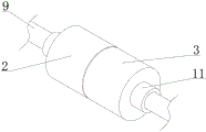
FIG. 2 is a schematic perspective view of the present invention;
FIG. 3 is an enlarged schematic view of the structure at A of FIG. 1 according to the present invention;
fig. 4 is a schematic structural view of the clamping device of the present invention.
In the figure: 1. a wiring terminal; 2. a first housing; 3. a second housing; 4. a sliding plate; 5. connecting blocks; 6. a sleeve; 7. a spring; 8. a clamping device; 801. an arc-shaped splint; 802. a threaded rod; 803. rotating the block; 9. a wire; 10. a bolt; 11. and (4) a protective shell.
Detailed Description
As shown in fig. 1 to 4, a quick connection structure of a low-voltage short-circuit wire comprises a connection terminal 1, a first shell 2 and a second shell 3; one end of the first shell 2 and one end of the second shell 3 are connecting parts, and the other end is a free end; the first shell 2 and the second shell 3 form a shell component with a cavity structure after being connected at a connecting part, and a connecting terminal 1 is arranged in the cavity structure and positioned at the connecting part of the first shell 2 and the second shell 3; the free ends of the first shell 2 and the second shell 3 are provided with wire channels, and two ends of the wiring terminal 1 are provided with wire slots; the connecting part of the first shell 2 and the second shell 3 is a structure which can be separated or folded and is fastened after being folded.
And wire fastening mechanisms are arranged at the wire slots at the two ends of the wiring terminal 1 and are used for fastening wires after the wires are inserted into the wire slots.
The wire fastening mechanism comprises a bolt 10 perpendicular to the wire insertion slot, the bolt 10 is in threaded connection with an opening in the side wall of the wire insertion slot, and the end of the bolt 10 can be in abutting contact with the side face of the wire.
In order to reduce the influence on the wire when the wire is pulled by external force in use, sliding plates 4 are arranged on two sides of the wiring terminal 1 and respectively positioned in the inner cavities of the first shell 2 and the second shell 3, and the sliding plates 4 can move to approach the wiring terminal 1 or be far away from the wiring terminal 1; a sleeve 6 is arranged on the lead passage, and springs 7 are arranged outside the sleeve 6 and between the sliding plate 4 and the free end of the first shell 2 and between the sliding plate 4 and the free end of the second shell 3.
An accommodating cavity is arranged between the sliding plate 4 and the wiring terminal 1, and the accommodating cavity can accommodate a lead with a certain length.
The side face of the sliding plate 4 close to the free ends of the first shell 2 and the second shell 3 is fixedly provided with a connecting block 5, one end of the sleeve 6 is fixedly connected with the connecting block 5, the side wall of the other end of the sleeve is provided with a clamping device 8, and the clamping device 8 can tightly press and fasten the wires in the sleeve 6.
The specific structure of the clamping device comprises an arc-shaped clamping plate 801, a threaded rod 802 is movably connected to the upper surface of the arc-shaped clamping plate 801 through a rotating shaft, a rotating block 803 is fixedly connected to the top end of the threaded rod 802, and the inner arc surface of the arc-shaped clamping plate 801 can tightly press and fasten a lead in the sleeve 6.
Protective shells 11 are arranged on the two outer sides of the first shell 2 and the second shell 3, and the protective shells 11 can seal the clamping device 8.
The protective shell 11 is rotatably connected to the first housing 2 and the second housing 3, and further, a threaded connection structure may be adopted.
The following examples are offered for further understanding and implementation by those of ordinary skill in the art:
referring to fig. 1 to 4, a quick connection structure of a low-voltage short-circuit wire includes a connection terminal 1, two ends of the connection terminal 1 are respectively connected with a first housing 2 and a second housing 3 in a threaded manner, a sealing rubber ring is arranged at the threaded connection position of the first housing 2 and the second housing 3, and the sealing property of the connection position of the first housing 2 and the second housing 3 is improved by the arrangement of the sealing rubber ring;
one side of the first shell 2 and one side of the second shell 3 are both in threaded connection with a protective shell 11, and the protective shell 11 can effectively protect the clamping device 8;
one side of the protective shell 11 is provided with a waterproof rubber ring, the inner side walls of the first shell 1 and the second shell 3 are both connected with a sliding plate 4 through sliding chutes in a sliding manner, in the installation process of the device, a wire 9 with a certain length needs to be reserved on one side of the sliding plate 4, when an external wire 9 is accidentally pulled, the wire 9 drives the connecting block 5 and the sliding plate 4 to move through the sleeve 6, the spring 7 deforms through the movement of the connecting block 5, the pulling force on the wire 9 can be effectively reduced through the deformation generated by the spring 7, in the deformation generating process of the spring 7, the reserved wire 9 is stretched, and when the tension disappears and the spring 7 resets, a part of the reserved wire 9 resets;
one side fixedly connected with connecting block 5 of sliding plate 4, one side fixedly connected with sleeve pipe 6 of connecting block 5, spring 7 has been cup jointed on the surface of sleeve pipe 6, the one end fixed connection of spring 7 is in one side of connecting block 5, the quantity of spring 7 is two, two spring 7's the other end difference fixed connection is in the inner wall of first casing 2 and second casing 3, one side threaded connection of sleeve pipe 6 upper surface has clamping device 8, clamping device 8 includes arc splint 801, arc splint 801's upper surface has threaded rod 802 through pivot swing joint, threaded rod 802 threaded connection is in the inner wall of sleeve 6, the top fixedly connected with turning block 803 of threaded rod 802, binding post 1's both sides all have wire 9 through the wiring groove joint, the material of wire 9 is the electric wire of softer type, the equal threaded connection in both sides of binding post 1 upper surface has bolt 10.
The utility model discloses when using, adopt following step:
1) inserting the wires at two ends into the first shell 2 and the second shell 3 from two ends respectively, and inserting the end parts of the wires into the jacks at two ends of the wiring terminal 1 at the connecting part;
2) the wiring of the cable is effectively fastened and clamped through the bolt 10;
3) the lead 9 is clamped by the clamping device 8 in the sleeve 6, specifically, the rotating block 803 is rotated to drive the arc-shaped clamping plate 801 to move downwards through the threaded rod 802, so that one side of the arc-shaped clamping plate 801 is tightly attached to the surface of the lead 9, and the first shell 3 and the second shell 3 are connected to the wiring terminal 1 in a threaded manner;
4) then the protective shell 11 is rotated to be screwed on one side of the first shell 2 and the second shell 3 so as to protect the clamping device 8 and the sleeve 6;
the connection operation of the device is completed through the above steps.