Background
In recent years, high-altitude parabolic events are frequently reported, and due to the fact that the height of a high-rise building is higher and higher, objects falling from the high-rise building can cause great threat to life and property safety of pedestrians below the building due to potential energy of the objects. In such events, many high-altitude parabolic starters are children and young children who do not have this risk awareness, and may have serious consequences due to the guardian's temporary inattentiveness. On the other hand, recent accidents of falling from the building of infants are frequent, on one hand, due to carelessness of guardians, on the other hand, the risk of theft of high-rise buildings is low, and the accidents are generally related to no installation of anti-theft windows.
However, the ventilation of the window opening is also an inevitable requirement in daily life, so that a device capable of limiting the opening degree of the window is necessary. At present, the limiting devices on the market are mostly used for vertical push-pull type doors and windows, the technology on the one hand is mature, and the research and development on the limiting devices of horizontal push-pull type doors and windows are relatively less. Under the prior art, the horizontal push-pull type door and window limiting device is generally arranged on a door and window frame and can influence the maximum stroke of the door and window.
For example, a "sliding window limiting locking device" disclosed in chinese patent document, publication No. 104948044, includes a limiting plate and a bolt; the limiting plate is a strip-shaped sheet and is provided with a hollow strip-shaped limiting chute; the lower edge of the limiting plate is arranged at the upper edge of the lower frame of the sliding window; the bolt is a base with a bolt hole, a bolt rod capable of moving along the hole direction is arranged on the bolt hole, when the sliding window is closed, one end of the bolt rod can penetrate through the limiting sliding groove to be close to one end of the adjacent sliding window in a straight insertion mode, and the end head of the bolt rod 4 can slide in the limiting sliding groove; the base is fixed on the outer edge of the window frame at the side edge of the adjacent sliding window.
SUMMERY OF THE UTILITY MODEL
The utility model relates to an overcome the problem of the biggest stroke of prior art's influence door and window, provide a horizontal plug-type door and window stop device, realize spacing to door and window under the prerequisite that does not influence the biggest degree of opening and shutting of door and window.
In order to achieve the above purpose, the utility model adopts the following technical scheme:
a horizontal sliding door and window limiting device comprises a sinking type mounting shell, a limiting block and a locking block, and is characterized in that,
the sinking type mounting shell comprises a fixing panel and a sinking groove, the fixing panel is parallel to the surface of the door and window frame, and the fixing panel is used for integrally and fixedly mounting the limiting device on the door and window; the sinking groove is embedded into the door and window frame, and the limiting block is arranged in the sinking groove; the limiting block can be in an opening state and a closing state according to different positions, and in the opening state, the limiting block is partially positioned in the sinking groove, partially extends out of the sinking groove and exceeds the plane of the fixed panel; under the closed state, the whole limiting block is positioned in the sinking groove.
The limiting device is integrally embedded into the door and window frame, and the fixed panel is parallel to the surface of the door and window frame, so that when the limiting device is in a closed state, the normal opening and closing and the stroke of the door and window cannot be influenced. In addition, according to specific door and window size, can set up stop device in different positions.
Preferably, the limiting block is arranged in the sinking groove through a rotating shaft.
Rotation is a motion design mode for realizing the switching of the limiting device between an opening state and a closing state, but the rotation is as follows: save space, characteristics such as reciprocating motion tolerance is good the utility model discloses well selection is the motion mode of stopper, can be so that stop device overall structure is simple more durable.
Preferably, the sinking type mounting shell is provided with two positioning holes, and the positions of the positioning holes respectively correspond to the opening state and the closing state of the limiting block; the limiting block is provided with a spring plunger, and the ball head of the spring plunger corresponds to the two positioning holes.
The spring plunger cooperates the locating hole to open and do the location to the stopper with closed state can make the actual operation in-process, and the stopper has obvious card to go into to feel when two positions, and the person of facilitating the use confirms the position.
Preferably, an opening is formed at the intersection of one side of the sinking groove and the fixing panel, the opening forms a locking gap for inserting the locking block, and the limiting block is provided with a clamping block extending towards the locking gap; when the limiting block is in the opening state, the locking block can be inserted into the locking gap to prevent the limiting block from returning to the closing state; when the stopper is in during the closed condition, screens piece and the bottom contact of heavy groove, plays limiting displacement, prevents that the stopper from rotating excessively.
The upper opening of the sinking groove is provided with a clamping block according to the size and the motion track of the limiting block in the sinking groove, so as to be matched with the locking block; the scheme uses a simple mechanical structure to achieve the control of the motion stroke of the limiting block and realizes the locking purpose.
Preferably, the locking block comprises a rotary column and a rotary clamping block, the rotary clamping block is semicircular, and when the rotary clamping block is located in the locking gap, the position of the limiting block is locked, so that the locking block cannot be switched between an opening state and a closing state.
The semicircular rotating fixture block is screwed into the locking gap, the limiting block can be locked, the limiting block is not interfered to move after being screwed out, the structure is simple, and the function is complete.
Preferably, the locking block is provided with a lock, and the lock can lock the locking block in an opening state and a closing state.
If the locking block structure is too simple, even if children or even infants can simply open, the guardian does not play a good role in protection in the occasion where the guardian is not present temporarily, and therefore a lockset needs to be additionally arranged on the locking block to achieve an effective protection effect.
Preferably, the lock is a remote control lock.
When encountering emergency, the guardian needs to go out, and children or infants break away from the guardian, if the guardian forgets to open the door and window limiting device in the dead-lock house, the remote control lock can be used to cooperate with the door and window limiting device in the wireless network house, so that the effective protection effect is achieved.
Therefore, the utility model discloses following beneficial effect has: (1) the maximum travel of the door and the window is not influenced; (2) the protection effect is good.
Detailed Description
The present invention will be further described with reference to the accompanying drawings and the detailed description.
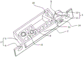
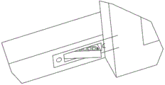
Embodiment 1, as shown in fig. 1, fig. 2, fig. 3, and fig. 4, a horizontal push-pull door and window limiting device includes:
the anti-theft door and window frame is characterized in that the sunken mounting shell 1 comprises a fixing panel 4 and a sunken groove 5, the fixing panel 4 is parallel to the surface of a door and window frame, and the fixing panel 4 is used for integrally and fixedly mounting the limiting device on the door and window; the sinking groove 5 is embedded into the door and window frame and is used for arranging the limiting block 2; the limiting block 2 can be in an opening state and a closing state according to different positions, and in the opening state, the limiting block 2 is partially positioned in the sinking groove 5, partially extends out of the sinking groove 5 and exceeds the plane of the fixed panel 4; under the closed state, the whole stopper 3 is located in heavy groove 5.
The width of the section bar for the door and window frame is generally between 30 mm-100 mm, so that the width of the fixing panel 4 used in the embodiment is 25mm, the length is 110mm, and the depth of the sinking groove 5 is 25 mm. The overall installation position of the limiting device can also determine the limiting stroke, and the limiting stroke can be determined according to different sizes of doors and windows and the requirements of specific application scenes.
Furthermore, a rotating shaft 6 is arranged on the sinking type mounting shell 1, the rotating shaft 6 also penetrates through the limiting block 2, and the limiting block 2 can rotate around the rotating shaft 6.
A hole with the diameter of 6mm is processed at the same position on the sunken mounting shell 1 and the limiting block 2, a metal shaft is used as the rotating shaft 6, the diameter of the head of the metal shaft is slightly larger, and the head of the metal shaft is in interference fit with the hole to provide certain retaining force.
Furthermore, two positioning holes 7 are formed in the sinking type mounting shell 1, and the positions of the positioning holes 7 correspond to the opening state and the closing state of the limiting block 2 respectively; the limiting block 2 is provided with a spring plunger 8, and the ball head of the spring plunger 8 corresponds to the two positioning holes 7.
The utility model discloses a shorter spring plunger 8, external diameter 8mm, length 20 mm. When the limiting block 2 is in a closed state, the ball head of the spring plunger 8 is located at the position corresponding to the positioning hole 7 in the closed state, and the surface, parallel to the fixed panel, of the limiting block 2 is pressed, so that the ball head can move to the position corresponding to the positioning hole 7 in the open state.
Furthermore, an opening 9 is formed at the intersection of one side of the sinking groove 5 and the fixing panel 4, an oblique clamping block 10 is arranged on the limiting block 2 close to the opening 9, when the limiting block 2 is in an opening state, a locking gap 11 is formed between the clamping block 10 and the opening 9, and the locking block 3 can be inserted into the locking gap 11 to prevent the limiting block 2 from returning to a closing state; when the limiting block 2 is in a closed state, the clamping block 10 is in contact with the bottom of the sinking groove 5, so that a limiting effect is achieved, and the limiting block 2 is prevented from rotating excessively.
The inclination angle of the blocking block 10 is designed according to the size of the limiting block 2 and the position of the rotating shaft 6. The utility model provides an angle of inclination is 60.
Further, the locking block 3 comprises a rotary column 12 and a rotary fixture block 13, the rotary fixture block 13 is semicircular, and when the rotary fixture block 13 is located in the locking gap 11, the position of the limiting block 2 is locked, so that the switching between the opening state and the closing state cannot be realized.
The semicircular rotary latch 13 has a radius of 25mm and can be rotated into the locking space 11 by rotating around the rotary post 12.
Further, a lock 14 is arranged on the locking block 3, and the lock 14 can lock the locking block 3 in an opening state and a closing state.
Further, latch 14 is a remote control latch.