Background
The steel truss rigid stiffening suspension cable structural design adopts a rigid suspension rod to connect a steel beam with the rigid suspension cable, the connection mode is generally pin joint (hinge joint), namely ear plate pin holes are respectively arranged at the node of the stiffening suspension cable and the upper chord member and are concentric with ear plate pin holes at two ends of the suspension rod, and pin holes can be inserted for ensuring pin shafts, the design mostly adopts the mode of amplifying the stiffening suspension cable and the ear plate pin holes at the node of the upper chord member, so that the structural design cannot eliminate the structural linearity and the design inconsistency generated by pin hole gaps no matter what mode (such as a support method and a top pushing method) is adopted.
SUMMERY OF THE UTILITY MODEL
The utility model aims at providing an utilize existing jib to support device of rigidity span wire utilizes the rigidity jib to prop the adjustment jib of hanging down straightness as assembling stiffening string's bearing structure (depression bar) earlier, utilizes the splayed of setting at the lower extreme to it is spacing to go up the lower extreme and sets up, treats that stiffening string closes the dragon and accomplishes the back, cancels spacing system's conversion of carrying on, becomes the jib by the pressurized and draws the structure, and each component remains throughout in the design position in the installation, and the installation of rigidity span wire is accomplished.
To achieve these objects and other advantages in accordance with the purpose of the invention, there is provided an apparatus for installation of an existing boom support rigid suspension cable, comprising:
a boom;
the first rotating hinge structure and the second rotating hinge structure are the same and respectively comprise a group of steel supports and a pin shaft, the group of steel supports are arranged oppositely, and the pin shaft is detachably arranged between the group of steel supports; the lower end of the suspender is connected with a pin shaft of the first rotary hinge structure in an inserting manner, and the upper end of the suspender is connected with a pin shaft of the second rotary hinge structure in an inserting manner;
the first limiting device is arranged at the bottom end of the hanging rod, and the second limiting device is arranged at the top end of the hanging rod;
a splayed bracing structure which fixes the suspension rod; the splayed inclined strut structure comprises a hoop and a pair of adjustable steel pull rods, the hoop is fixed on the hanging rod in a pre-tightening mode, the adjustable steel pull rods are symmetrically arranged on two sides of the hoop, and one end of each adjustable steel pull rod is fixed with the hoop through an ear plate.
Preferably, the first limiting device is a screw structure with adjustable height arranged between a pair of square cushion blocks, and a pin shaft of the first rotary hinge structure is in point-surface contact with the first limiting device;
the second limiting device is a screw structure with adjustable height arranged between the wedge-shaped cushion block and the square cushion block, the top surface of the second limiting device is attached to the stiffening chord, and the second limiting device is in point-surface contact with the pin shaft of the second rotary hinge structure.
Preferably, the steel support is provided with a stiffening plate. The utility model discloses at least, include following beneficial effect:
1. the method is used as a supporting member by means of a permanent structure, the installation of an auxiliary rigid suspension cable is not required to be supported temporarily, the investment of temporary engineering is reduced, the engineering cost is greatly saved, and the installation work efficiency is improved.
2. The method of the utility model is fast to operate, the structure is stressed clearly, and the safety factor is increased.
3. The utility model discloses the safety risk of temporary structure use production in a large number has been avoided.
4. The utility model discloses avoided traditional interim support to occupy the bridge floor space as bearing structure.
5. The utility model discloses to installing very strong practicality of rigidity atress structure.
6. The utility model discloses adjustable eight characters prop the steel pull rod and set up simply, it is convenient to hang straightness positioning to the steel davit, and can have enough to meet the need the use repeatedly, save the cost.
7. The first limiting device and the second limiting device are small in pressure bearing deformation, and linear control is guaranteed.
Additional advantages, objects, and features of the invention will be set forth in part in the description which follows and in part will become apparent to those having ordinary skill in the art upon examination of the following or may be learned from practice of the invention.
Detailed Description
The present invention is further described in detail below with reference to examples so that those skilled in the art can implement the invention with reference to the description.
In the description of the present invention, the terms "lateral", "longitudinal", "up", "down", "front", "back", "left", "right", "vertical", "horizontal", "top", "bottom", "inner", "outer", etc. indicate orientations or positional relationships based on the orientations or positional relationships shown in the drawings, and are only for convenience of description and simplicity of description, and do not indicate or imply that the device or element referred to must have a particular orientation, be constructed and operated in a particular orientation, and therefore, should not be construed as limiting the present invention.
Example 1
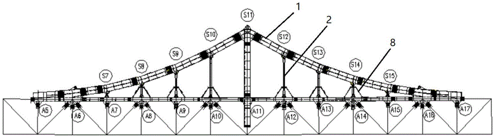
This embodiment relies on engineering once rock jialing river bridge, for double-deck 270m rigid suspension cable 1 stiffening steel truss bridge of main span, it is internal first in the bridge of the same kind, wherein, will the utility model discloses an installation method that utilizes existing jib 2 to support rigid suspension cable 1 is applied to stiffening string 3's closure installation, as shown in fig. 1 ~ 4, includes following steps:
step one, mounting the lower end of a suspender 2 on a steel beam 12 through a first rotary hinge structure 4, firstly applying a certain lifting force to the suspender 2 during mounting, then inserting the lower end of the suspender 2 in place through a pin shaft 13 of the first rotary hinge structure 4, enabling the pin shaft 13 of the first rotary hinge structure 4 to be in a position in a tensioned state, and placing a first limiting device 6 between the bottom end of the suspender 2 and the steel beam 12;
step two, adjusting and limiting the suspender 2 to ensure that the suspender 2 keeps a vertical state;
hoisting the stiffening chord 3 to a corresponding position, applying a certain lifting force to the stiffening chord 3, inserting the upper end of the suspender 2 in place through the pin shaft 13 of the second rotary hinge structure 5, enabling the pin shaft 13 of the second rotary hinge structure 5 to be in a pulled state, and placing a second limiting device 7 between the top end of the suspender 2 and the stiffening chord 3;
and step four, completing closure construction of the stiffening chord 3 and construction of the high-strength bolt, and dismantling the first limiting device 6 and the second limiting device 7 to change the hanger rod 2 from being pressed into being pulled, so as to complete conversion of a stress system.
In the technical solution, the utility model discloses utilize permanent structure rigidity jib 2 to draw and press dual performance, make jib 2 replace interim the support as the pressurized state when the chord of putting more energy into 3 installations. When utilizing permanent structure rigidity jib 2, because the limit that changes hinge structure to have the gap, if change for the displacement that the state of being drawn can produce 2-3mm in the pressurized state, directly lead to the whole deformation of steel construction or even can't fold up, the utility model discloses a let change hinge structure in the position of the state of being drawn in advance before the pressurized to it becomes the tension and produces the structural deformation that the displacement arouses to have avoided installing stiffening chord 3 after.
In a preferred embodiment of the installation method for supporting the rigid suspension cable 1 by using the existing suspension rod 2, in the second step, the suspension rod 2 is fixed by the splayed inclined strut structure 8, so that the suspension rod 2 keeps a vertical state and is smoothly connected with the upper chord and the lower chord by the pin shaft 13.
In above-mentioned technical scheme, in order to guarantee that jib 2 is in the vertical state of design, stop device and 2 atresss of jib belong to the point face contact, and the easy production of contact slides and 2 angles of jib can't be guaranteed, and the eight characters of adoption prop the structure middle part and be equipped with adjustable steel pull rod, and the eight characters prop upper portion and jib 2 and adopt staple bolt 9 to be connected, and this structure atress is reliable, convenient operation.
In a preferred embodiment of the present application, the splayed bracing structure 8 comprises:
and the hoop 9 is made of finish-rolled deformed steel bars and is pre-tightened to be embraced on the suspender 2. In this example, the pretension of the single finish-rolled thread steel is 250 KN.
A pair of adjustable shaped steel pull rod 10, its symmetry sets up in the both sides of staple bolt 9, the both ends of adjustable shaped steel pull rod 10 all are connected with staple bolt 9 and girder steel 12 through otic placode 11.
In a preferred embodiment of the present application of the mounting method for supporting a rigid suspension cable 1 by means of an existing boom 2, said first swivel joint construction 4 and said second swivel joint construction 5 are identical; the first hinge structure 4 includes:
the steel support bases 14 are arranged oppositely, and stiffening plates 15 are arranged on the steel support bases 14;
and a pin 13 which is detachably mounted between a set of steel supports 14.
In a preferred embodiment of the installation method for supporting the rigid suspension cable 1 by using the existing suspension rod 2, as shown in fig. 5 to 6, the first limiting device 6 is a pair of square cushion blocks 16, a screw 18 structure square cushion block 16 capable of adjusting height is arranged between the pair of square cushion blocks 16, the height between the pair of square cushion blocks 16 can be adjusted, and the pin shaft 13 of the first pivot hinge structure 4 is in point-surface contact with the first limiting device 6;
the second limiting device 7 is of a structure that a screw 18 capable of adjusting height is arranged between a wedge-shaped cushion block 17 and a square cushion block 16, the height between the wedge-shaped cushion block 17 and the square cushion block 16 can be adjusted, the top surface of the second limiting device 7 is attached to the stiffening string 3, and the second limiting device 7 is in point-surface contact with the pin shaft 13 of the second rotary hinge structure 5.
In the first step and the third step, when the first limiting device and the second limiting device are placed in the groove, the heights of the first limiting device and the second limiting device are adjusted to the designed height through the corresponding screw rods; in the fourth step, before the first limiting device and the second limiting device are removed, the heights of the first limiting device and the second limiting device are reduced by adjusting the corresponding screw rods.
Example 2
An apparatus for installation of an existing boom support rigid suspension cable, comprising:
a suspender 2;
the hinge structure comprises a first rotating hinge structure 4 and a second rotating hinge structure 5, wherein the first rotating hinge structure 4 and the second rotating hinge structure 5 are the same and respectively comprise a group of steel supports 14 and a pin shaft 13, the group of steel supports 14 are oppositely arranged, and the pin shaft 13 is detachably arranged between the group of steel supports 14; the lower end of the suspender 2 is connected with a pin shaft 13 of the first rotary hinge structure 4 in an inserting manner, and the upper end of the suspender 2 is connected with a pin shaft 13 of the second rotary hinge structure 5 in an inserting manner;
the device comprises a first limiting device 6 and a second limiting device 7, wherein the first limiting device 6 is arranged at the bottom end of the suspender 2, and the second limiting device 7 is arranged at the top end of the suspender 2;
a splayed bracing structure 8 which fixes the suspension rod 2; the splayed inclined strut structure 8 comprises a hoop 9 and a pair of adjustable steel pull rods 10, the hoop 9 is fixed on the suspension rod 2 in a pre-tightening mode, the adjustable steel pull rods 10 are symmetrically arranged on two sides of the hoop 9, and one end of each adjustable steel pull rod 10 is fixed with the hoop 9 through an ear plate 11.
In a preferred embodiment of the present application, which is used for the installation of the rigid suspension cable 1 supported by the existing suspension rod 2, as shown in fig. 5 to 6, the first limiting device 6 is a screw 18 structure with adjustable height arranged between a pair of square cushion blocks 16, and the pin shaft 13 of the first pivot hinge structure 4 is in point-surface contact with the first limiting device 6;
the second limiting device 7 is of a structure that a screw 18 capable of adjusting height is arranged between a wedge-shaped cushion block 17 and a square cushion block 16, the top surface of the second limiting device 7 is attached to the stiffening chord 3, and the second limiting device 7 is in point-surface contact with the pin shaft 13 of the second rotary hinge structure 5. The height-adjustable screw 18 in the present embodiment is composed of an internally threaded sleeve and a pair of screws provided at both ends of the internally threaded sleeve.
In a preferred embodiment of the present application for an installation of an existing boom 2 supporting a rigid suspension cable 1, the steel support 14 is provided with stiffening plates 15.
While the embodiments of the invention have been disclosed above, it is not limited to the applications listed in the description and the embodiments, which are fully applicable in all kinds of fields suitable for the invention, and further modifications may be readily made by those skilled in the art, and the invention is therefore not limited to the specific details and embodiments shown and described herein, without departing from the general concept defined by the claims and their equivalents.