CN212404236U - Insulator iron hat hot galvanizing device - Google Patents
Insulator iron hat hot galvanizing device Download PDFInfo
- Publication number
- CN212404236U CN212404236U CN202020663947.1U CN202020663947U CN212404236U CN 212404236 U CN212404236 U CN 212404236U CN 202020663947 U CN202020663947 U CN 202020663947U CN 212404236 U CN212404236 U CN 212404236U
- Authority
- CN
- China
- Prior art keywords
- cylinder
- constant temperature
- welded
- heating constant
- close
- Prior art date
- Legal status (The legal status is an assumption and is not a legal conclusion. Google has not performed a legal analysis and makes no representation as to the accuracy of the status listed.)
- Expired - Fee Related
Links
- 238000005246 galvanizing Methods 0.000 title claims abstract description 23
- 239000012212 insulator Substances 0.000 title claims abstract description 23
- XEEYBQQBJWHFJM-UHFFFAOYSA-N Iron Chemical compound [Fe] XEEYBQQBJWHFJM-UHFFFAOYSA-N 0.000 title abstract description 56
- 229910052742 iron Inorganic materials 0.000 title abstract description 28
- 239000007788 liquid Substances 0.000 claims abstract description 25
- 238000010438 heat treatment Methods 0.000 claims abstract description 19
- 238000003466 welding Methods 0.000 claims abstract description 7
- 235000017166 Bambusa arundinacea Nutrition 0.000 claims description 6
- 235000017491 Bambusa tulda Nutrition 0.000 claims description 6
- 241001330002 Bambuseae Species 0.000 claims description 6
- 235000015334 Phyllostachys viridis Nutrition 0.000 claims description 6
- 239000011425 bamboo Substances 0.000 claims description 6
- 239000000463 material Substances 0.000 claims description 2
- HCHKCACWOHOZIP-UHFFFAOYSA-N Zinc Chemical compound [Zn] HCHKCACWOHOZIP-UHFFFAOYSA-N 0.000 abstract description 20
- 229910052725 zinc Inorganic materials 0.000 abstract description 20
- 239000011701 zinc Substances 0.000 abstract description 20
- 238000000034 method Methods 0.000 abstract description 7
- 239000007787 solid Substances 0.000 abstract description 6
- 238000009434 installation Methods 0.000 description 10
- 238000004519 manufacturing process Methods 0.000 description 5
- 230000000694 effects Effects 0.000 description 3
- 238000007747 plating Methods 0.000 description 3
- TVEXGJYMHHTVKP-UHFFFAOYSA-N 6-oxabicyclo[3.2.1]oct-3-en-7-one Chemical compound C1C2C(=O)OC1C=CC2 TVEXGJYMHHTVKP-UHFFFAOYSA-N 0.000 description 2
- 229910000831 Steel Inorganic materials 0.000 description 2
- 238000005536 corrosion prevention Methods 0.000 description 2
- 239000002184 metal Substances 0.000 description 2
- 229910052751 metal Inorganic materials 0.000 description 2
- 239000010959 steel Substances 0.000 description 2
- FGRBYDKOBBBPOI-UHFFFAOYSA-N 10,10-dioxo-2-[4-(N-phenylanilino)phenyl]thioxanthen-9-one Chemical compound O=C1c2ccccc2S(=O)(=O)c2ccc(cc12)-c1ccc(cc1)N(c1ccccc1)c1ccccc1 FGRBYDKOBBBPOI-UHFFFAOYSA-N 0.000 description 1
- 230000009286 beneficial effect Effects 0.000 description 1
- JEIPFZHSYJVQDO-UHFFFAOYSA-N iron(III) oxide Inorganic materials O=[Fe]O[Fe]=O JEIPFZHSYJVQDO-UHFFFAOYSA-N 0.000 description 1
Images

Landscapes
- Coating With Molten Metal (AREA)
Abstract
The utility model discloses an insulator iron hat hot-galvanize device relates to hot-galvanize equipment technical field. This insulator iron hat hot dip galvanizing device, including heating constant temperature frame and cylinder, the welding of heating constant temperature frame one side is close to bottom edge center department outward and has a pressure bar, and the welding of heating constant temperature frame opposite side surface is close to top edge has a collection thing frame, and heating constant temperature frame top is close to two corners and all has welded the stopper, and the slip inlays between the relative surface of two stoppers and is equipped with the back shaft. This insulator iron hat hot dip galvanizing device, during the use, make first pull ring and second pull ring can stabilize the connection through current couple equipment, make the solid fixed cylinder can use the back shaft to rotate as the fixed point through control pneumatic rod, make the cylinder can effectively dip in the zinc liquid, place the iron hat in the cylinder in a proper amount, drive the cylinder through motor box internal arrangement and effectively rotate, make the inside iron hat of cylinder can evenly galvanize, make the actual galvanizing process in reduce artificial operation.
Description
Technical Field
The utility model relates to a hot-galvanize equipment technical field specifically is an insulator iron hat hot-galvanize device.
Background
Hot galvanizing is also called hot dip galvanizing and hot dip galvanizing, is an effective metal corrosion prevention mode, is mainly used for metal structure facilities in various industries, and is used for immersing a steel piece after rust removal into molten zinc liquid to enable a zinc layer to be attached to the surface of the steel piece, so as to achieve the purpose of corrosion prevention.
SUMMERY OF THE UTILITY MODEL
The utility model provides an insulator iron hat hot-galvanize device uses the reducible manual operation of people of the actual zinc-plating in-process in back, improves operating personnel's security, can effectively improve actual production efficiency simultaneously, and effectively prevents to get rid of unnecessary liquid zinc in-process liquid zinc and splashes the healthy safety production influence to production environment and operating personnel on every side everywhere.
In order to achieve the above purpose, the utility model discloses a following technical scheme realizes: an insulator iron cap hot galvanizing device comprises a heating constant temperature frame and a roller, wherein a pneumatic rod is welded at the position, close to the center of the edge of the bottom, outside one side of the heating constant temperature frame, the edge of the outer surface of the other side of the heating constant temperature frame, which is close to the top, is welded with a material collecting frame, the top of the heating constant temperature frame, which is close to two corners, is welded with limit blocks, a support shaft is embedded between the two limit blocks and the outer surface, a supporting block is slidably sleeved on the outer surface of the supporting shaft between the two limiting blocks, a fixed cylinder is welded at the top of the supporting block, a first pull ring is welded at the center of one end of the fixed cylinder, a liquid passing port is arranged at one end of the fixed cylinder and positioned below the first pull ring, the outer surface of the fixed cylinder is positioned on one side of the liquid passing port, a liquid seepage port is formed in the outer surface of the fixed cylinder, a supporting table is welded on the outer surface of the fixed cylinder close to the edge of the other end of the fixed cylinder, and a motor box is arranged on the top of the supporting table.
Carry out the zinc-plating of iron hat in order to make equipment can be convenient, conduct the utility model relates to an insulator iron hat hot-galvanize device, the welding of pneumatic rod top has the fixed block, and the welding of fixed block one side surface center department has the second pull ring.
Should have the realization of function in order to make the cylinder normally go on, conduct the utility model relates to an insulator iron hat hot-galvanize device, the fixed cylinder other end has a plurality of connecting blocks, every along the welding of circumferencial direction equidistance the inside equal slip of connecting block one side surface center department and be located the fixed cylinder inlays and is equipped with the trace axle.
In order to make motor box internal arrangement can effectively drive the cylinder and rotate, conduct the utility model relates to an insulator iron hat hot-galvanize device, every the equal sliding sleeve of interlock off-axial surface is equipped with backing roll, one of them interlock axle one end extends to fixed section of thick bamboo outside, and interlock off-axial surface is close to one end edge cover and is equipped with the belt pulley.
Should have the realization of function in order to make equipment normally go on, conduct the utility model relates to an insulator cap hot-galvanize device, motor box one side surface center department slides and runs through there is the pivot, and the pivot surface is close to one end edge and also overlaps and be equipped with the belt pulley, two the cover is equipped with the belt between the belt pulley surface.
In order to prevent effectively that zinc liquid from splashing everywhere at the actual operation in-process, as the utility model relates to an insulator iron hat hot-galvanize device, the inside bottom surface center department of solid fixed cylinder slides and inlays and be equipped with spacing back shaft, and inside spacing back shaft one end extended to the cylinder, a plurality of weeping mouths have been seted up to cylinder surface equidistance.
The utility model provides an insulator iron hat hot-galvanize device. The method has the following beneficial effects:
(1) this insulator iron hat hot dip galvanizing device, during the use, make first pull ring and second pull ring can stabilize the connection through current couple equipment, make the solid fixed cylinder can use the back shaft to rotate as the fixed point through control pneumatic rod, make the cylinder can effectively dip in the zinc liquid, place the iron hat in the cylinder in proper amount, drive the cylinder through motor box internal arrangement and effectively rotate, make the inside iron hat of cylinder can evenly galvanize, make the actual galvanizing in-process reduce artificial operation, improve equipment in-service use effect.
(2) This insulator iron hat hot dip galvanizing device, during the use, effectively raise the fixed cylinder through the pneumatic rod, make pivoted cylinder can effectually get rid of unnecessary molten zinc inside the fixed cylinder, the condition that molten zinc splashes everywhere takes place when effectively preventing to get rid of unnecessary molten zinc, unnecessary molten zinc passes through the sepage mouth and falls into the constant temperature frame of heating again, continues to improve the fixed cylinder and makes the inside iron hat of cylinder can effectively collect the processing through the collection thing frame, improves actual production efficiency.
Drawings
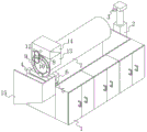
Fig. 1 is a front perspective view of the present invention;
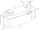
fig. 2 is a rear perspective view of the present invention;
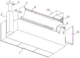
fig. 3 is a left side sectional perspective view of the present invention;
fig. 4 is a bottom perspective view of the present invention.
In the figure: 1. heating the constant temperature frame; 2. a pneumatic rod; 3. a second tab; 4. a limiting block; 5. a support shaft; 6. a support block; 7. a fixed cylinder; 8. a drum; 9. connecting blocks; 10. a linkage shaft; 11. a support roller; 12. a belt pulley; 13. a support table; 14. a motor box; 15. collecting frames; 16. a first pull ring.
Detailed Description
The technical solutions in the embodiments of the present invention will be described clearly and completely with reference to the accompanying drawings in the embodiments of the present invention, and it is obvious that the described embodiments are only some embodiments of the present invention, not all embodiments.
Examples of which are illustrated in the accompanying drawings, wherein like reference numerals refer to the same or similar elements or elements having the same or similar function throughout. The embodiments described below with reference to the drawings are exemplary and intended to be used for explaining the present invention, and should not be construed as limiting the present invention.
Referring to fig. 1-4, the present invention provides a technical solution: the utility model provides an insulator cap hot dip galvanizing device, including heating constant temperature frame 1 and cylinder 8, it has pressure bar 2 to heat 1 one side of constant temperature frame and weld near bottom edge center department outward, it has collection thing frame 15 to heat 1 opposite side surface of constant temperature frame and weld near top edge, it has stopper 4 all to weld near two corners all to heat 1 top of constant temperature frame, it inlays and is equipped with back shaft 5 to slide between two stopper 4 relative surfaces, the slip cover is equipped with supporting shoe 6 between 5 surfaces of back shaft are located two stoppers 4, 6 top welds of supporting shoe have solid fixed cylinder 7, 7 one end center departments of solid fixed cylinder weld have first pull ring 16, solid fixed cylinder 7 one end is located first pull ring 16 below and has been seted up the liquid mouth, gu fixed cylinder 7 surfaces is located liquid mouth one side and has been seted up the liquid mouth, gu fixed cylinder 7 surfaces is close to other end.
In this embodiment: the installation foundation of other functional components of the equipment is provided by the establishment of the heating constant temperature frame 1, the equipment can efficiently carry out the galvanizing operation of the iron cap by the establishment of the roller 8, the equipment can conveniently enter the fixed cylinder 7 into the zinc liquid by the establishment of the air pressure rod 2, and simultaneously can conveniently send the galvanized iron cap into the collection frame 15, thereby improving the actual use effect of the equipment, the finished product collection after the galvanizing is conveniently carried out by the establishment of the collection frame 15, the installation and the setting of the supporting shaft 5 are conveniently carried out by the establishment of the limiting block 4, the installation and the setting of the supporting block 6 are conveniently carried out by the establishment of the supporting shaft 5, the installation and the setting of the fixed cylinder 7 are conveniently carried out by the establishment of the fixed cylinder 7, the installation and the setting of other functional components of the equipment are conveniently carried out by the establishment of the fixed cylinder 7, the equipment can normally realize the due function, the equipment can normally rotate by the establishment of the first pull ring 16 in cooperation with, the equipment can efficiently carry out the galvanizing of the iron cap by the arrangement of the liquid passing port, the equipment can effectively prevent the zinc liquid from splashing everywhere when the redundant zinc liquid is removed by the arrangement of the liquid permeating port, the redundant zinc liquid can effectively fall back into the heating constant temperature frame 1, the installation and the arrangement of the motor box 14 are conveniently carried out by the arrangement of the supporting table 13, and the equipment can obtain the power for realizing the normal function by the arrangement of the motor box 14.
Specifically, the top end of the air pressure rod 2 is welded with a fixed block, and the center of the outer surface of one side of the fixed block is welded with a second pull ring 3.
In this embodiment: the installation setting of second pull ring 3 is conveniently carried out through the establishment of fixed block, makes equipment normally carry out the realization that has the function through establishing cooperation first pull ring 16 of second pull ring 3.
Concretely, the welding of the fixed section of thick bamboo 7 other end along circumferencial direction equidistance has a plurality of connecting blocks 9, and every connecting block 9 one side surface center department just is located fixed section of thick bamboo 7 inside and all slides and inlays and be equipped with interlock axle 10.
In this embodiment: the installation and arrangement of the linkage shaft 10 are conveniently carried out through the establishment of the connecting block 9, and the installation and arrangement of the supporting roller 11 are conveniently carried out through the establishment of the linkage shaft 10.
Specifically, the outer surface of each linkage shaft 10 is slidably sleeved with a supporting roller 11, one end of one linkage shaft 10 extends to the outside of the fixed cylinder 7, and the outer surface of the linkage shaft 10, which is close to one end edge, is sleeved with a belt pulley 12.
In this embodiment: the internal device of the motor box 14 can effectively drive the roller 8 to rotate by arranging the supporting roller 11, and the internal device of the motor box 14 can effectively drive the roller 8 to rotate by arranging the belt pulley 12.
Specifically, the center of the outer surface of one side of the motor box 14 is slidably penetrated with a rotating shaft, the outer surface of the rotating shaft is also sleeved with a belt pulley 12 near one end, and a belt is sleeved between the outer surfaces of the two belt pulleys 12.
In this embodiment: the belt pulley 12 is convenient to install and arrange through the establishment of the rotating shaft, and the belt pulley 12 is matched with the establishment of the belt to enable the internal device of the motor box 14 to effectively drive the roller 8 to rotate.
Specifically, the inside bottom surface center department of a fixed section of thick bamboo 7 slides and inlays and be equipped with spacing back shaft, and inside spacing back shaft one end extended to cylinder 8, a plurality of weeping mouths had been seted up to 8 surface equidistance of cylinder.
In this embodiment: the installation setting of cylinder 8 is conveniently carried out through establishing of spacing back shaft, and the zinc-plating of the inside iron hat of cylinder can be carried out to equipment efficient through establishing of weeping mouth, improves actual work efficiency.
When in use, the first pull ring 16 and the second pull ring 3 can be stably connected through the existing hook equipment, the fixed cylinder 7 can rotate by taking the support shaft 5 as a fixed point through controlling the air pressure rod 2, the roller 7 can be effectively immersed into the zinc liquid, the iron cap is properly placed in the roller 8, the roller 8 is driven to effectively rotate through the internal device of the motor box 14, the iron cap in the roller 8 can be uniformly galvanized, the artificial operation in the actual galvanizing process is reduced, the actual using effect of the equipment is improved, meanwhile, the fixed cylinder 7 is effectively lifted through the air pressure rod 2, the rotating roller 8 can effectively throw the redundant zinc liquid into the fixed cylinder 7, the situation that the zinc liquid splashes around when the redundant zinc liquid is removed is effectively prevented, the redundant zinc liquid falls into the heating constant temperature frame 1 again through the liquid seepage port, the fixed cylinder 7 is continuously improved, and the iron cap in the roller 8 can be effectively collected through the collection frame 15, the actual production efficiency is improved.
The above, only be the concrete implementation of the preferred embodiment of the present invention, but the protection scope of the present invention is not limited thereto, and any person skilled in the art is in the technical scope of the present invention, according to the technical solution of the present invention and the utility model, the concept of which is equivalent to replace or change, should be covered within the protection scope of the present invention.
Claims (6)
1. The utility model provides an insulator cap hot dip galvanizing device, includes heating constant temperature frame (1) and cylinder (8), its characterized in that: the heating constant temperature frame is characterized in that a pressure rod (2) is welded at the position, close to the center of the bottom edge, outside one side of the heating constant temperature frame (1), a material collecting frame (15) is welded at the position, close to the edge of the top, of the outer surface of the other side of the heating constant temperature frame (1), limiting blocks (4) are welded at the position, close to two corners, of the top of the heating constant temperature frame (1), a supporting shaft (5) is embedded between the two opposite outer surfaces of the limiting blocks (4) in a sliding mode, a supporting block (6) is sleeved on the outer surface of the supporting shaft (5) in a sliding mode between the two limiting blocks (4), a fixed cylinder (7) is welded at the top of the supporting block (6), a first pull ring (16) is welded at the center of one end of the fixed cylinder (7), a liquid passing port is formed in a position below the first pull ring (16) at, and a motor box (14) is arranged at the top of the support table (13).
2. The hot galvanizing device for the insulator cap according to claim 1, characterized in that: the top end of the air pressure rod (2) is welded with a fixed block, and the center of the outer surface of one side of the fixed block is welded with a second pull ring (3).
3. The hot galvanizing device for the insulator cap according to claim 1, characterized in that: the welding of the equidistance of circumferencial direction is followed to the fixed cylinder (7) other end has a plurality of connecting blocks (9), every connecting block (9) one side surface center department just is located fixed cylinder (7) inside and all slides and inlays and be equipped with trace axle (10).
4. The hot galvanizing device for the insulator cap according to claim 3, characterized in that: every interlock axle (10) surface all slides and overlaps and be equipped with backing roll (11), one of them interlock axle (10) one end extends to fixed section of thick bamboo (7) outside, and interlock axle (10) surface is close to one end edge and is equipped with belt pulley (12).
5. The hot galvanizing device for the insulator cap according to claim 1, characterized in that: motor box (14) one side surface center department slides and runs through there is the pivot, and the pivot surface is close to one end edge and also overlaps and be equipped with belt pulley (12), two the cover is equipped with the belt between belt pulley (12) surface.
6. The hot galvanizing device for the insulator cap according to claim 1, characterized in that: fixed section of thick bamboo (7) inside bottom surface center department slides and inlays and be equipped with spacing back shaft, and inside spacing back shaft one end extended to cylinder (8), a plurality of weeping mouths have been seted up to cylinder (8) surface equidistance.
Priority Applications (1)
| Application Number | Priority Date | Filing Date | Title |
|---|---|---|---|
| CN202020663947.1U CN212404236U (en) | 2020-04-27 | 2020-04-27 | Insulator iron hat hot galvanizing device |
Applications Claiming Priority (1)
| Application Number | Priority Date | Filing Date | Title |
|---|---|---|---|
| CN202020663947.1U CN212404236U (en) | 2020-04-27 | 2020-04-27 | Insulator iron hat hot galvanizing device |
Publications (1)
| Publication Number | Publication Date |
|---|---|
| CN212404236U true CN212404236U (en) | 2021-01-26 |
Family
ID=74299548
Family Applications (1)
| Application Number | Title | Priority Date | Filing Date |
|---|---|---|---|
| CN202020663947.1U Expired - Fee Related CN212404236U (en) | 2020-04-27 | 2020-04-27 | Insulator iron hat hot galvanizing device |
Country Status (1)
| Country | Link |
|---|---|
| CN (1) | CN212404236U (en) |
-
2020
- 2020-04-27 CN CN202020663947.1U patent/CN212404236U/en not_active Expired - Fee Related
Similar Documents
| Publication | Publication Date | Title |
|---|---|---|
| CN106734266A (en) | A kind of efficient hot rolled steel plate cooling device | |
| CN114717637A (en) | Battery steel casing device of falling shell | |
| CN211503713U (en) | Feeding equipment for metallurgical furnace | |
| CN114134441A (en) | A steel wire galvanizing system | |
| CN109161832A (en) | A kind of automatic angle steel galvanized machine | |
| CN210529014U (en) | Welded tube zinc-plating holding frame | |
| CN217948264U (en) | Box type coating turnover hot galvanizing device | |
| CN206706176U (en) | A kind of steel pipe galvanized bath deslagging device | |
| CN210341369U (en) | Cloth discharging device and overflow dyeing machine using same | |
| CN216889869U (en) | Device for fishing bottom slag of zinc pot | |
| CN211760704U (en) | Surface polishing device for heat-preservation pipe | |
| CN211330051U (en) | Energy-saving environment-friendly efficient chain rust-proof lubricating machine | |
| CN211947199U (en) | Device suitable for carbon steel GR60 material metal galvanizing | |
| CN218532054U (en) | Product cleaning device in hot galvanizing process | |
| CN210751615U (en) | Filtering and cooling device for spheroidizing furnace | |
| CN205874475U (en) | Safety of iron and steel electric stove discharging device that overturns | |
| CN205974582U (en) | Safety protection device for furnace top operation of continuous annealing furnace | |
| CN218900980U (en) | Zinc-plating device that iron wire production was used | |
| CN208680169U (en) | A kind of four-high mill rack working roll wear-resistant liner special hoisting tooling | |
| CN223226140U (en) | A hot-dip galvanizing zinc pot insulation device | |
| CN221522685U (en) | Solid high-frequency quenching device | |
| CN211545208U (en) | Cooling, guiding and conveying device for hot-dip galvanized steel pipe | |
| CN215089893U (en) | Galvanized steel sheet finisher work roll frame | |
| CN217942316U (en) | Welding equipment is used in processing of aluminium iron foundry goods | |
| CN205152312U (en) | Equipment of work piece air jaundice |
Legal Events
| Date | Code | Title | Description |
|---|---|---|---|
| GR01 | Patent grant | ||
| GR01 | Patent grant | ||
| CF01 | Termination of patent right due to non-payment of annual fee |
Granted publication date: 20210126 Termination date: 20210427 |
|
| CF01 | Termination of patent right due to non-payment of annual fee |