PTFE inside lining flaring turn-ups instrument
Technical Field
The utility model relates to a tetrafluoro inside lining processing technology field specifically is a tetrafluoro inside lining flaring turn-ups instrument.
Background
Tetrafluoro is a polymer of tetrafluoroethylene, polytetrafluoroethylene is widely applied to various products needing acid-base resistance and organic solvents, and has no toxicity to human bodies, does not absorb moisture, is non-combustible, is extremely stable to oxygen and ultraviolet rays, so the polytetrafluoroethylene has excellent weather resistance, is often used for pipeline linings, and needs to be flared and flanged when being used for pipe linings, and at the moment, a tetrafluoro lining flaring and flanging tool is needed, but the existing tetrafluoro lining flaring and flanging tool has many problems or defects:
traditional tetrafluoro inside lining flaring turn-ups instrument in the in-service use, the device width is not convenient for adjust, makes its device can't adjust according to the pipe fitting specification for the device can't be applicable to the pipe fitting of different specifications, makes the device application range when using little.
SUMMERY OF THE UTILITY MODEL
An object of the utility model is to provide a tetrafluoro inside lining flaring turn-ups instrument to solve the little problem of application range that provides among the above-mentioned background art.
In order to achieve the above object, the utility model provides a following technical scheme: the utility model provides a tetrafluoro inside lining flaring turn-ups instrument, includes install bin, support frame, mounting bracket and turn-ups frame, two sets of support frames are installed through the bolt in the inside of install bin, the mounting bracket is installed through the nut in the top of support frame, the internally mounted of mounting bracket has two sets of spacing dishes, the pipe fitting has been placed between the spacing dish, the turn-ups frame is installed to the top both sides of install bin.
Preferably, the support frame is internally provided with a support plate, the two sides of the top of the support plate are welded with support rods, and the top of each support rod is welded with a screw rod.
Preferably, install the mounting panel in the mounting bracket, the top welding of mounting panel has the installation rail, and the equidistance of installation rail is equipped with the draw-in groove, and the welding of top one side of mounting panel has the baffle.
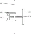
Preferably, the flanging frame is internally provided with an installation rod, two groups of limiting arm rods are sleeved on the outer side of the installation rod, a penetrating threaded rod is installed inside the installation rod through a shaft sleeve, a flanging disc is installed at one end of the threaded rod through a rotating shaft, and a handle rod is welded at the other end of the threaded rod.
Preferably, one side of the limiting disc is welded with a limiting rod, and the other side of the limiting disc is welded with an adjusting frame.
Preferably, two groups of foot rests are welded on two sides of the bottom of the installation box, and a drain valve is welded at the bottom of the front face of the installation box.
Compared with the prior art, the beneficial effects of the utility model are that: this tetrafluoro inside lining flaring turn-ups instrument is rational in infrastructure, has following advantage:
(1) the clamping grooves are equidistantly arranged at the top of the mounting rail, when the device is used for width adjustment, the clamping grooves can provide mounting positions for the limiting rods and the adjusting frames on two sides of the limiting discs, the distance between the two groups of limiting discs can be conveniently adjusted through the plurality of groups of clamping grooves, and the adjusting frames are fixed on one side of the baffle plate through bolts on one side of the adjusting frames, so that the positions of the limiting discs can be conveniently fixed, the distance between the two groups of limiting discs can be conveniently adjusted, the adjustability of the device is improved, the spacing discs can be adjusted according to the specifications of pipe fittings, the device is suitable for pipe fittings with different specifications, and the range of the device in use is expanded;
(2) the limiting arm rods are movably mounted on the two sides of the mounting rod, when flaring and flanging are carried out, two groups of limiting arm rods are moved to the two sides of the connecting disc at the two ends of the pipe fitting, the limiting arm rods are tightly held and fixed on the two sides of the connecting disc, the threaded rod and the pipe fitting can be determined to be on the same horizontal line through the two groups of limiting arm rods, the threaded rod can be driven to rotate through rotation of the handle rod, the flanging disc can be driven to rotate in the horizontal direction through rotation of the threaded rod, the polytetrafluoroethylene lining in the pipe fitting can be tightened through horizontal movement of the flanging disc, flaring and flanging are carried out on the polytetrafluoroethylene lining in the pipe fitting, the arrangement of the limiting arm rods enables the device to be more labor-saving when flaring and flanging are carried out, adjustment according;
(3) through installing the support frame in the bottom both sides of mounting bracket, when the device was assembled, can fix the backup pad in the inside of install bin through the bolt, insert the threaded rod at backup pad top in the inside screw of mounting panel to can fix the mounting panel at the top of bracing piece through nut and threaded rod cooperation, and the diameter of bracing piece is greater than the inside screw of mounting panel, can guarantee the steadiness of mounting bracket installation, and the setting up of support frame makes the device be convenient for assemble.
Drawings
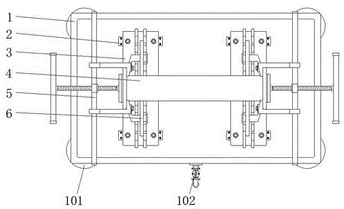
Fig. 1 is a schematic top view of the present invention;
FIG. 2 is a schematic view of the supporting frame of the present invention;
fig. 3 is a schematic structural view of the mounting frame of the present invention;
fig. 4 is a schematic view of the structure of the flanging frame of the present invention.
In the figure: 1. installing a box; 101. a foot rest; 102. a drain valve; 2. a support frame; 201. a support plate; 202. A support bar; 203. a screw; 3. a mounting frame; 301. mounting a plate; 302. mounting a rail; 303. a card slot; 304. a baffle plate; 4. a pipe fitting; 5. a flanging frame; 501. mounting a rod; 502. a limiting arm lever; 503. a threaded rod; 504. a flanging disc; 505. a handle bar; 6. a limiting disc; 601. a limiting rod; 602. an adjusting frame.
Detailed Description
The technical solutions in the embodiments of the present invention will be described clearly and completely with reference to the accompanying drawings in the embodiments of the present invention, and it is obvious that the described embodiments are only some embodiments of the present invention, not all embodiments. Based on the embodiments in the present invention, all other embodiments obtained by a person skilled in the art without creative work belong to the protection scope of the present invention.
Referring to fig. 1-4, the present invention provides an embodiment: a tetrafluoro lining flaring flanging tool comprises an installation box 1, support frames 2, an installation frame 3 and a flanging frame 5, wherein two groups of foot stands 101 are welded on two sides of the bottom of the installation box 1, a drain valve 102 is welded on the bottom of the front face of the installation box 1, two groups of support frames 2 are installed inside the installation box 1 through bolts, the installation frame 3 is installed on the top of each support frame 2 through nuts, an installation plate 301 is installed inside the installation frame 3, equidistant screw holes are formed in the installation plate 301, installation rails 302 are welded on the top of the installation plate 301, clamping grooves 303 are formed in the equidistant positions of the installation rails 302, a baffle 304 is welded on one side of the top of the installation plate 301, a bolt groove is formed inside the baffle 304 and can provide an installation position for a bolt on one side of an adjusting frame 602, two groups of limiting discs 6 are installed inside the installation frame 3, limiting rods 601 are welded, the pipe fittings 4 are arranged between the limiting discs 6.
Specifically, when the device is used for width adjustment, the clamping grooves 303 can provide mounting positions for the limiting rods 601 and the adjusting frames 602 on the two sides of the limiting discs 6, the distance between the two groups of limiting discs 6 can be conveniently adjusted through the plurality of groups of clamping grooves 303, and the adjusting frames 602 are fixed on one sides of the baffle plates 304 through bolts on one sides of the adjusting frames 602, so that the positions of the limiting discs 6 can be conveniently fixed, the distance between the two groups of limiting discs 6 can be conveniently adjusted, the adjustability of the device is improved, the spacing between the limiting discs 6 can be adjusted according to the specification of the pipe fittings 4, the device is suitable for the pipe fittings 4 with different specifications, and the range of the device in use is expanded;
two groups of support frames 2 are installed inside the installation box 1 through bolts, a support plate 201 is installed inside each support frame 2, support rods 202 are welded to two sides of the top of each support plate 201, and a screw 203 is welded to the top of each support rod 202;
specifically, when the device is assembled, the supporting plate 201 can be fixed inside the installation box 1 through bolts, two groups of supporting rods 202 are welded at the top of the supporting plate 201, the diameter of each supporting rod 202 is larger than that of a screw hole inside the installation plate 301, a screw rod 203 at the top of each supporting rod 202 is inserted into the screw hole inside the installation plate 301, the installation plate 301 can be fixed at the top of each supporting rod 202 by rotating a nut to be connected with the screw rod 203, the device is convenient to assemble, the installation plate 301 is fixedly installed through the two groups of supporting rods 202, the installation stability of the installation frame 3 can be guaranteed, and the installation of the supporting frame 2 is convenient to assemble;
the two sides of the top of the installation box 1 are provided with flanging frames 5, installation rods 501 are installed in the flanging frames 5, two groups of limiting arm rods 502 are sleeved on the outer sides of the installation rods 501, penetrating threaded rods 503 are installed inside the installation rods 501 through shaft sleeves, a flanging disc 504 is installed at one end of each threaded rod 503 through a rotating shaft, and a handle bar 505 is welded at the other end of each threaded rod 503;
concretely, when carrying out the flaring turn-ups, remove the connection pad both sides at 4 both ends of pipe fitting with two sets of spacing armed levers 502 earlier, make spacing armed lever 502 hold tightly and fix in the connection pad both sides, can confirm threaded rod 503 and pipe fitting 4 on same water flat line through two sets of spacing armed levers 502, it can drive threaded rod 503 and rotate to hold pole 505 through holding, rotation through threaded rod 503 can drive turn-ups dish 504 and carry out the rotation of horizontal direction, the horizontal migration of turn-ups dish 504 can tighten up the inside tetrafluoro inside lining of pipe fitting 4 with the connection pad cooperation at 4 both ends of pipe fitting, make the inside tetrafluoro inside lining of pipe fitting 4 carry out the flaring turn-ups operation, setting up of spacing armed lever 502 makes the device more laborsaving when carrying out the flaring turn-ups use, also be convenient for adjust according to 4 specifications of pipe fitting, convenience.
The working principle is as follows: when in use, firstly, the plurality of groups of clamping grooves 303 arranged in the mounting rail 302 can provide adjusting positions for the limiting discs 6, the distance between the two groups of limiting discs 6 can be conveniently adjusted through the matching of the plurality of groups of clamping grooves 303, the limiting rods 601 at the two sides of the limiting discs 6 and the adjusting frame 602, the adjusting frame 602 is fixed at one side of the baffle 304 through the bolts at one side of the adjusting frame 602, so that the positions of the limiting discs 6 can be conveniently fixed, the distance between the two groups of limiting discs 6 can be conveniently adjusted, the adjustability of the device is increased, the spacing discs 6 can be adjusted according to the specification of the pipe fitting 4, the device is suitable for pipe fittings 4 with different specifications, the range of the device is expanded when in use, the pipe fitting 4 is placed between the two groups of limiting discs 6, the two groups of limiting arm rods 502 are firstly moved to the two sides of the connecting discs at the two ends of the pipe fitting 4, can confirm threaded rod 503 and pipe fitting 4 on same water flat line through two sets of spacing armed lever 502, rotate through holding handle bar 505 and can drive threaded rod 503 and rotate, rotation through threaded rod 503 can drive turn-ups dish 504 and carry out the rotation of horizontal direction, turn-ups dish 504 horizontal migration can with the connection pad cooperation at 4 both ends of pipe fitting can tighten up the inside tetrafluoro inside lining of pipe fitting 4, make the inside tetrafluoro inside lining of pipe fitting 4 carry out flaring turn-ups operation, spacing armed lever 502 set up make the device more laborsaving when carrying out the flaring turn-ups use, also be convenient for adjust according to 4 specifications of pipe fitting, convenience of equipment uses.
It is obvious to a person skilled in the art that the invention is not restricted to details of the above-described exemplary embodiments, but that it can be implemented in other specific forms without departing from the spirit or essential characteristics of the invention. The present embodiments are therefore to be considered in all respects as illustrative and not restrictive, the scope of the invention being indicated by the appended claims rather than by the foregoing description, and all changes which come within the meaning and range of equivalency of the claims are therefore intended to be embraced therein. Any reference sign in a claim should not be construed as limiting the claim concerned.