Background
In the production process of the circuit board, a copper foil film material is required to be pasted on the circuit board. In the prior art, the process of mounting the copper foil membrane material on the circuit board, no matter loading, mounting and discharging, is still in a semi-automatic production state, the processing operation at each processing position can not lack manual participation, the labor intensity of workers is increased, the labor cost of enterprise production is increased, and the production efficiency is reduced.
SUMMERY OF THE UTILITY MODEL
An object of the utility model is to provide a sticking film machine aims at solving among the prior art and has the problem that relies on artifical participation, production efficiency to the process of circuit board dress copper foil membrane material to hang.
In order to achieve the above object, the utility model adopts the following technical scheme: a film laminator comprising: a frame; the first feeding mechanism comprises a flaky film material storage seat and a first feeding structure, and the flaky film material storage seat and the first feeding structure are both arranged on the rack; the feeding conveying mechanism comprises a placing seat, a transmission guide rail and a driving structure, wherein the transmission guide rail and the driving structure are both arranged on the rack, the placing seat is connected to the transmission guide rail in a sliding manner, the driving structure is in driving connection with the placing seat, the placing seat is provided with a first station and a second station on the transmission guide rail, and the first feeding structure is used for taking the film materials on the flaky film material storing seat and transferring the film materials to the placing seat positioned on the first station; the second feeding mechanism comprises a circuit board storage seat, a middle platform and a second feeding structure, the circuit board storage seat, the middle platform and the second feeding structure are all arranged on the rack, and the circuit board stored in the circuit board storage seat is transferred to the middle platform by the second feeding structure; the film sticking mechanism is assembled on the rack, is positioned between the second station and the middle platform, takes the film material on the placing seat at the second station, transfers the film material to the middle platform and a circuit board for film sticking to obtain a product piece, and transfers the product piece to the placing seat at the second station; the blanking mechanism comprises a blanking seat and a blanking structure, the blanking seat and the blanking structure are both installed in the frame, and the blanking structure takes the product pieces on the placing seat positioned for the second work and transfers the product pieces to the blanking seat for storage.
Optionally, the film laminator further comprises: the CCD detection device is arranged on the frame and is positioned between the second station and the middle platform; the control device is electrically connected with the first feeding structure, the feeding conveying mechanism, the second feeding structure, the film sticking mechanism, the discharging structure and the CCD detection device respectively; the film sticking mechanism comprises a first moving device, a horizontal adjusting device and a film sticking adsorption plate, the first moving device is installed on the rack, the horizontal adjusting device is connected to the first moving device, the film sticking adsorption plate is connected to the horizontal adjusting device, and the first moving device, the horizontal adjusting device and the film sticking adsorption plate are all electrically connected with the control device.
Optionally, the first feeding structure includes a second moving device and a first feeding sucker assembly, the second moving device is installed in the rack, the first feeding sucker assembly is connected to the second moving device, and the second moving device and the first feeding sucker assembly are both electrically connected to the control device.
Optionally, the second feeding structure includes a third moving device, a second feeding sucker assembly, and a third moving device, the second feeding sucker assembly is connected to the third moving device, and the third moving device and the second feeding sucker assembly are both electrically connected to the control device.
Optionally, the driving structure comprises a driving motor and a screw-nut pair, the driving motor is mounted on the frame, a screw of the screw-nut pair is connected with a power rotating shaft of the driving motor, a nut of the screw-nut pair is connected with the placing seat, and the driving motor is electrically connected with the control device.
Optionally, the film laminator further comprises: the middle conveying rail and the middle driving device are both arranged on the frame, the middle platform is connected to the middle conveying rail in a sliding mode, the middle driving device is connected with the middle platform in a driving mode, the middle platform is provided with a film pasting station and a paper tearing station on the middle conveying rail, the middle driving device drives the middle platform to move between the film pasting station and the paper tearing station, the film pasting station, the CCD detection device and the second station are arranged on the same straight line, and the middle driving device is electrically connected with the control device; the paper tearing device is installed on the rack and electrically connected with the control device, and the paper tearing device is used for tearing off the film material protection paper of the product piece located at the paper tearing station.
Optionally, the intermediate platform comprises an upper platform and a lower platform; the middle conveying rail comprises a first guide rail group and a second guide rail group, the first guide rail group is parallel to the second guide rail group, two guide rails of the second guide rail group are positioned between the two guide rails of the first guide rail group, the upper platform is slidably connected to the first guide rail group, the lower platform is slidably connected to the second guide rail group, and the upper platform and the lower platform are not interfered with each other in the sliding process; the middle driving device comprises a first middle driver and a second middle driver, the first middle driver is in driving connection with the upper platform, the second middle driver is in driving connection with the lower platform, and the first middle driver and the second middle driver are both electrically connected with the control device.
Optionally, a sliding block is arranged on the second guide rail group, and the lower platform is connected to the sliding block in a lifting and sliding manner; the sliding block is connected with the second intermediate driver; the film sticking machine further comprises an auxiliary lifting cylinder, the auxiliary lifting cylinder is connected to the sliding block, the end part of a piston rod of the lifting cylinder is connected to the lower platform, and the lifting cylinder is electrically connected with the control device.
Optionally, the paper tearing device comprises: the lifting pressing plate assembly comprises a cylinder and a pressing plate, the cylinder is mounted on the frame, the pressing plate is connected to the end of a piston rod of the cylinder, the pressing plate is located right above the paper tearing station, the pressing plate is provided with a notch, and the cylinder is electrically connected with the control device; the starting angle assembly comprises a starting angle cylinder and a starting angle roller, the starting angle cylinder is connected to the unfilled corner position of the pressing plate, and the starting angle roller is connected to the end part of a piston rod of the starting angle cylinder; the paper tearing clamp assembly comprises a paper tearing moving portion and a paper tearing clamp, the paper tearing moving portion is installed in the rack, the paper tearing clamp is connected to the paper tearing moving portion, and the paper tearing moving portion and the paper tearing clamp are both electrically connected with the control device.
Optionally, the film sticking machine further comprises a protective cover, the protective cover is assembled on the rack to form an assembly space, and the first feeding mechanism, the feeding conveying mechanism, the second feeding mechanism, the film sticking mechanism and the discharging mechanism are located in the assembly space.
The utility model discloses following beneficial effect has at least:
use the utility model discloses a sticking film machine pastes the copper foil membrane material to the circuit board, from slice copper foil membrane material loading, circuit board material loading, pastes and cover copper foil membrane material and unloading, all constitute the module through corresponding core in the sticking film machine and carry out the processing operation, need not to reuse any manpower at the subsides and cover the processing operation overall process and carry out supplementary processing production, realize full automatization processing production, saved the cost of labor to processing production efficiency has been improved greatly.
Detailed Description
Reference will now be made in detail to embodiments of the present invention, examples of which are illustrated in the accompanying drawings, wherein like reference numerals refer to the same or similar elements or elements having the same or similar function throughout. The embodiments described below with reference to the drawings are exemplary and intended to be used for explaining the present invention, and should not be construed as limiting the present invention.
In the description of the present invention, it is to be understood that the terms "length", "width", "upper", "lower", "front", "rear", "left", "right", "vertical", "horizontal", "top", "bottom", "inner", "outer", and the like indicate orientations or positional relationships based on those shown in the drawings, and are merely for convenience of description and simplicity of description, and do not indicate or imply that the device or element being referred to must have a particular orientation, be constructed and operated in a particular orientation, and thus, should not be construed as limiting the present invention.
Furthermore, the terms "first", "second", etc. are used for descriptive purposes only and are not to be construed as indicating or implying relative importance or implicitly indicating the number of technical features indicated. Thus, a feature defined as "first," "second," etc. may explicitly or implicitly include one or more of that feature. In the description of the present invention, "a plurality" means two or more unless specifically limited otherwise.
In the present invention, unless otherwise expressly stated or limited, the terms "mounted," "connected," and "fixed" are to be construed broadly and may, for example, be fixedly connected, detachably connected, or integrally formed; can be mechanically or electrically connected; either directly or indirectly through intervening media, either internally or in any other relationship. The specific meaning of the above terms in the present invention can be understood according to specific situations by those skilled in the art.
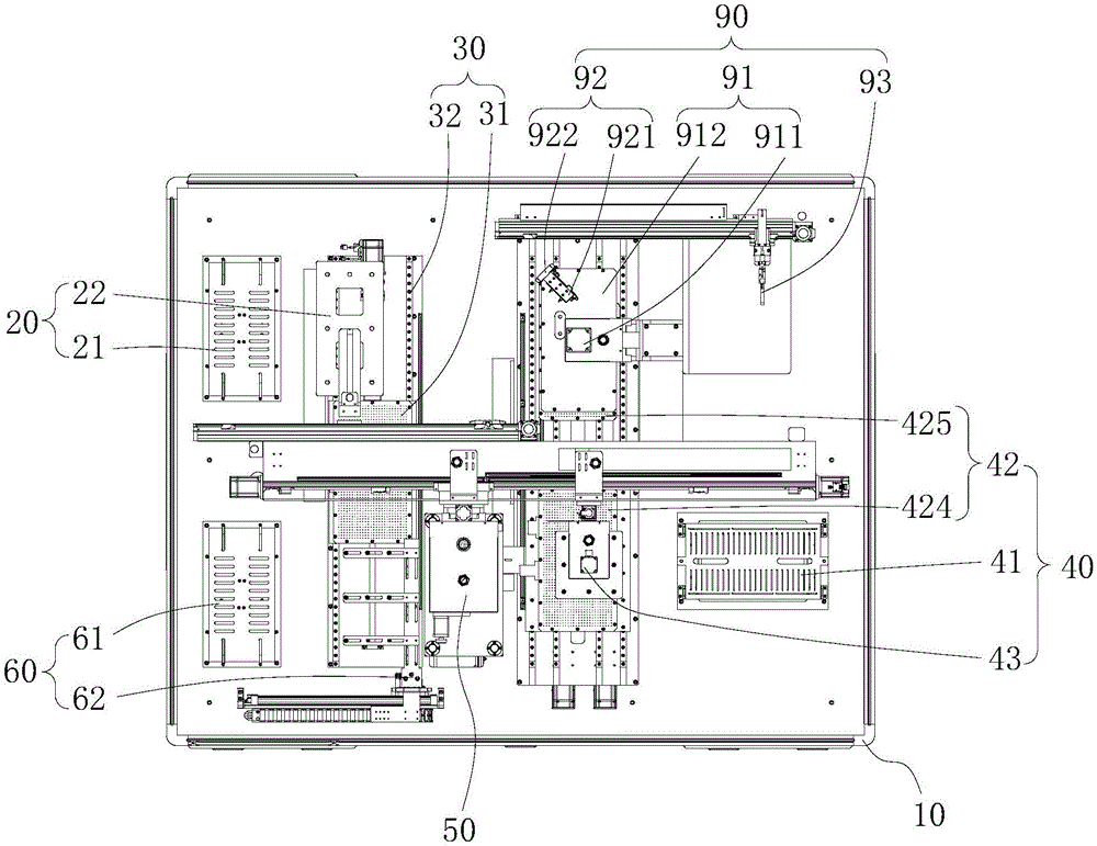
As shown in fig. 1 to 7, an embodiment of the present invention provides a film sticking machine, which is used for sticking a copper foil film material on a circuit board. The film sticking machine comprises a frame 10, a first feeding mechanism 20, a feeding conveying mechanism 30, a second feeding mechanism 40, a film sticking mechanism 50 and a discharging mechanism 60, wherein a plurality of modules form a core component module of the film sticking machine. Wherein, first feed mechanism 20 includes that the slice membrane material stores seat 21 and first feed structure 22, and material loading transport mechanism 30 is including placing seat 31, transmission rail 32 and drive structure 33, and second feed mechanism 40 includes that circuit board deposits seat 41, middle platform 42 and second feed structure 43, and unloading mechanism 60 includes unloading seat 61 and unloading structure 62. The flaky film material storage seat 21 and the first feeding structure 22 are both mounted on the rack 10, the flaky copper foil film material is placed on the flaky film material storage seat 21, and the flaky copper foil film material is conveyed to be fed through the first feeding structure 22 in the film pasting process. The driving guide rail 32 and the driving structure 33 are both mounted on the frame 10, the placing base 31 is slidably connected to the driving guide rail 32, the first feeding structure 22 conveys the copper foil film material on the sheet film material storing base 21 to the placing base 31, in the laminator, the driving structure 33 is in driving connection with the placing base 31, the placing base 31 has a first station and a second station on the driving guide rail 32, the placing base 31 waits for the copper foil film material conveyed from the sheet film material storing base 21 by the first feeding structure 22 at the first station, and the film material (i.e., the copper foil film material) on the placing base 31 is transferred from the first station to the second station along the driving guide rail 32 under the driving of the driving structure 33. In the laminator, the circuit board storage seat 41, the middle platform 42 and the second feeding structure 43 are all installed on the frame 10, and the second feeding structure 43 transfers the circuit board stored in the circuit board storage seat 41 to the middle platform 42 to wait for a laminating operation. The film sticking mechanism 50 is assembled on the frame 10, the film sticking mechanism 50 is located between the second station and the middle platform 42, and the film sticking mechanism 50 takes the film material on the placing seat 31 located at the second station and transfers the film material to the middle platform 42 to stick the film on the circuit board to obtain a product piece. After the film pasting is completed, the film pasting mechanism 50 takes the product pieces to be transferred from the middle platform 42 to the placing seat 31 located at the second station, then the blanking operation is performed, the blanking seat 61 and the blanking structure 62 are both installed on the frame 10, and the product pieces on the placing seat 31 located at the second work are taken by the blanking structure 62 and transferred to the blanking seat 61 for storage.
Use the utility model discloses a sticking film machine pastes the copper foil membrane material to the circuit board, from slice copper foil membrane material loading, circuit board material loading, paste copper foil membrane material and unloading, all through corresponding first feed mechanism 20 in the sticking film machine, material loading transport mechanism 30, second feed mechanism 40, sticking film mechanism 50 and unloading mechanism 60 these core component module carry out the processing operation, need not to reuse any manpower at the operation overall process of pasting and carry out the auxiliary processing production, realize full automated processing production, the cost of labor has been saved, and processing production efficiency has been improved greatly.
As shown in fig. 1 and 5, the laminator of the present invention further includes a CCD detecting device 70 and a control device 80, the CCD detecting device 70 is installed on the frame 10, the CCD detecting device 70 is located between the second station and the middle platform 42, in the process of the film sticking operation of the film sticking mechanism 50, the film sticking mechanism 50 takes the copper foil film material off the placing seat 31 of the second station and transfers the copper foil film material to the middle platform 42, the film sticking mechanism 50 carries the copper foil film material to pass through the CCD detection device 70, the CCD detecting device 70 detects whether the relative position of the film material on the film sticking mechanism 50 is correct, if the detected relative position is incorrect, corresponding position adjustment is needed (if the detected relative position is correct, no adjustment is needed), the film pasting mechanism 50 carries the film material to continue to be transferred to the middle platform 42, and pastes the film material on the circuit board located on the middle platform 42, and the film pasting operation is completed. And, first feed structure 22, material loading transport mechanism 30, second feed structure 43, pad pasting mechanism 50, blanking structure 62 and CCD detection device 70 respectively with controlling means 80 electric connection, that is to say, the utility model discloses a corresponding work order is sent to each part to the pad pasting machine through controlling means 80 to coordinate whole pad pasting course of working. In the present invention, the control device 80 may adopt but is not limited to MCU processing module, PCL processing module, etc. which are already applied in the prior art, and may also be other devices capable of implementing the control function, such as a microcomputer.
The film sticking mechanism 50 includes a first moving device 51, a horizontal adjustment device 52 and a film sticking adsorption plate 53, the first moving device 51 is installed on the frame 10, the horizontal adjustment device 52 is connected to the first moving device 51, the film sticking adsorption plate 53 is connected to the horizontal adjustment device 52, and the first moving device 51, the horizontal adjustment device 52 and the film sticking adsorption plate 53 are all electrically connected to the control device 80. After the placing seat 31 conveys the copper foil film material from the first station to the second station, the control device 80 controls the first moving device 51 to move to the position above the second station, then the film-sticking adsorption plate 53 is driven by the first moving device 51 to descend until contacting the copper foil film material, then the film-sticking adsorption plate 53 vacuumizes to adsorb the copper foil film material, then the film-sticking adsorption plate 53 ascends, then the copper foil film material is transferred to the position above the middle platform 42, and finally the film-sticking adsorption plate 53 descends again to stick the copper foil film material on the circuit board, so that the film-sticking operation is completed to obtain a product. After the film attaching operation is completed, the film attaching suction plate 53 continues to suck the product pieces and is brought back to above the second station by the first moving device 51, and then the product pieces are placed on the placing seat 31. Next, the blanking structure 62 transfers the product pieces placed on the placing seat 31 of the second station to the blanking seat 61 for storage. Then, the control device controls the driving structure 33 to drive the placing seat 31 to return to the first station from the second station, so as to circularly perform the loading and film-pasting processing operations.
As shown in fig. 6, in the present invention, the first feeding structure 22 includes a second moving device 221 and a first feeding suction cup assembly 222, the second moving device 221 is installed in the frame 10, the first feeding suction cup assembly 222 is connected to the second moving device 221, and the second moving device 221 and the first feeding suction cup assembly 222 are both electrically connected to the control device 80. The first feeding suction cup assembly 222 is used for absorbing the copper foil film material on the sheet film material storage base 21, and then the copper foil film material is transferred to the placing base 31 at the first station.
As shown in fig. 3, the second loading structure 43 includes a third moving device 431 and a second loading suction cup assembly 432, and the circuit boards placed on the circuit board storage seat 41 are transferred by suction. The third moving device 431 is installed on the rack 10, the second feeding chuck assembly 432 is connected to the third moving device 431, and both the third moving device 431 and the second feeding chuck assembly 432 are electrically connected to the control device 80.
The copper foil membrane material and the circuit board are adsorbed by an adsorption mode and then transferred, so that the surfaces of the copper foil membrane material and the circuit board can be protected from being scratched, and the product quality is ensured.
Further, the driving structure 33 includes a driving motor 331 and a screw nut pair 332, the driving motor 331 is mounted on the frame 10, a screw of the screw nut pair 332 is connected to a power rotating shaft of the driving motor 331, a nut of the screw nut pair 332 is connected to the placing base 31, and the driving motor 331 is electrically connected to the control device 80.
As shown in fig. 3, the laminator further includes an intermediate transfer rail 421, an intermediate drive device, and a paper tearing device 90. The copper foil membrane material surface covering that uses has one deck protection paper, covers copper foil membrane material subsides after on the circuit board, need tear this layer protection paper the utility model discloses a sticking film machine is then used and is torn paper device 90 and tear the paper operation. Specifically, the middle conveying rail 421 and the middle driving device are both mounted on the frame 10, the middle platform 42 is slidably connected to the middle conveying rail 421, the middle driving device is drivingly connected to the middle platform 42, the middle platform 42 has a film pasting station and a paper tearing station on the middle conveying rail 421, the film pasting operation is performed at the film pasting station, and the paper tearing operation is performed at the paper tearing station. The middle driving device drives the middle platform 42 to move at the film pasting station and the paper tearing station, the film pasting station, the CCD detecting device 70 and the second station are arranged on a straight line, the middle driving device is electrically connected with the control device 80, the paper tearing device 90 is installed on the frame 10, and the paper tearing device 90 is electrically connected with the control device 80. After the film adhering and adsorbing plate 53 adheres the copper foil film material to the circuit board, the control device 80 controls the film adhering and adsorbing plate 53 to stop adsorbing, the control device 80 controls the middle platform 42 to adsorb the circuit board at the same time, then the control device 80 controls the middle driving device to drive the middle platform 42 to transfer from the film adhering station to the paper tearing station along the middle conveying rail 421, and then the control device 80 controls the paper tearing device 90 to tear the film material protection paper of the product piece located at the paper tearing station.
In the present embodiment, the intermediate platform 42 includes an upper platform 424 and a lower platform 425, and the intermediate transfer rail 421 includes a first rail set 4211 and a second rail set 4212, the first rail set 4211 is parallel to the second rail set 4212, two rails of the second rail set 4212 are located between two rails of the first rail set 4211, the upper platform 424 is slidably connected to the first rail set 4211, and the lower platform 425 is slidably connected to the second rail set 4212, and the upper platform 424 and the lower platform 425 do not interfere with each other during the sliding process. The upper platform 424 and the lower platform 425 which are arranged up and down are adopted to alternately carry out conveying operation, so that the operation efficiency of film sticking and paper tearing can be greatly improved, and the assembly space is better and more fully utilized in the up-down arrangement mode. Correspondingly, the intermediate driving device includes a first intermediate driver and a second intermediate driver, the first intermediate driver is in driving connection with the upper platform 424, the second intermediate driver is in driving connection with the lower platform 425, and both the first intermediate driver and the second intermediate driver are electrically connected with the control device 80.
Further, a sliding block is arranged on the second guide rail group 4212, and the lower platform 425 is connected to the sliding block in a lifting and sliding manner; the slider is connected to the second intermediate drive. Because the lower platform 425 is arranged in a passing mode of penetrating through the upper platform 424, namely, the table top of the lower platform 425 is lower than that of the upper platform 424, in order to enable the table top of the lower platform 425 to be located at the same height as that of the table top of the upper platform 424 at both the film sticking station and the paper tearing station, the film sticking machine further comprises an auxiliary lifting cylinder, the auxiliary lifting cylinder is connected to the sliding block, the end part of a piston rod of the lifting cylinder is connected to the lower platform 425, and the lifting cylinder is electrically connected with the control device 80. When the lower platform 425 adsorbs the circuit board and is located at the film sticking station or the paper tearing station, the control device 80 controls the auxiliary lifting cylinder to drive the lower platform 425 to ascend to the same height as the table top of the upper platform 424, and after the film sticking operation or the paper tearing operation is completed, the control device 80 controls the auxiliary lifting cylinder to drive the lower platform 425 to descend.
As shown in fig. 2 and fig. 6, in the film sticking machine of the present invention, the paper tearing device 90 includes a lifting/lowering pressing plate assembly 91, a corner rising assembly 92 and a paper tearing clamp assembly 93, specifically, the lifting/lowering pressing plate assembly 91 includes a cylinder 911 and a pressing plate 912, the corner rising assembly 92 includes a corner rising cylinder 921 and a corner rising roller 922, and the paper tearing clamp assembly 93 includes a paper tearing moving portion 931 and a paper tearing clamp 932. In the assembling process, the cylinder 911 is installed in the frame 10, the pressing plate 912 is connected to the end portion of the piston rod of the cylinder 911, the pressing plate 912 is located right above the paper tearing station, the pressing plate 912 is provided with an unfilled corner, the cylinder 911 is electrically connected with the control device 80, the starting cylinder 921 is connected at the unfilled corner position of the pressing plate 912, the starting roller 922 is connected to the end portion of the piston rod of the starting cylinder 921, the paper tearing moving portion 931 is installed in the frame 10, the paper tearing clamp 932 is connected to the paper tearing moving portion 931, and both the paper tearing moving portion 931 and the paper tearing clamp 932 are electrically connected with the control device 80. After the film pasting operation is completed, the middle platform 42 carries the product piece to be transferred from the film pasting station to the paper tearing station, at the moment, the cylinder 911 drives the pressing plate 912 to descend and press the product piece, the starting angle roller 922 is attached to the protective paper, then the starting angle cylinder 921 stretches and retracts, the starting angle roller 922 rolls and rubs on the protective paper, the starting angle cylinder 921 drives the pressing plate 912 to ascend after the stretching of the starting angle cylinder 911 is completed, the protective paper and the copper foil are separated, meanwhile, the electrostatic separation is generated between the protective paper and the copper foil, and one corner of the protective paper is enabled to tilt relative to the copper foil. Then, the paper tearing moving portion 931 drives the paper tearing clamp 932 to move to a corner of the tilted protection paper, and the paper tearing clamp 932 protects the paper, and then the paper tearing moving portion 931 drives the paper tearing clamp 932 to move back, so that the protection paper is lifted away from the copper foil. After the paper tearing operation is completed, the control device 80 controls the middle platform 42 to return to the film sticking station from the paper tearing station, then the film sticking adsorption plate 53 transfers the product piece of the film sticking station to the placing seat 31 at the second station, and then the product piece on the placing seat 31 at the second station is transferred to the blanking seat 61 through the blanking structure 62 for storage.
As shown in fig. 1, prevent dust for each part of sticking film machine to guarantee the cleanness of processing environment, prevent to drop on the surface of product work piece and cause the pollution at the process dust of the copper foil coating membrane material of subsides, consequently, the utility model discloses a sticking film machine still includes safety cover 200, and safety cover 200 assembles and forms the fitting space in frame 10, and first feed mechanism 20, material loading transport mechanism 30, second feed mechanism 40, film sticking mechanism 50 and unloading mechanism 60 all are located the fitting space.
The utility model discloses in, first material loading sucking disc subassembly 222, second material loading sucking disc subassembly 432, pad pasting adsorption plate 53, place seat 31, middle platform 42 all adsorbs through the evacuation mode and stabilizes the material on it, therefore, this pad pasting machine is provided with vacuum pump and many branch control solenoid valve, vacuum pump and many branch control solenoid valve respectively with controlling means 80 electric connection, first material loading sucking disc subassembly 222, second material loading sucking disc subassembly 432, pad pasting adsorption plate 53, place seat 31, middle platform 42 is linked together with one of them branch road of many branch control solenoid valve respectively. Therefore, the control device 80 controls the on/off of each branch of the multi-branch control solenoid valve, so as to realize the vacuum adsorption or stop of the first feeding chuck assembly 222, the second feeding chuck assembly 432, the film adhering adsorption plate 53, the placing seat 31 or the intermediate platform 42.
The above description is only exemplary of the present invention and should not be taken as limiting the scope of the present invention, as any modifications, equivalents, improvements and the like made within the spirit and principles of the present invention are intended to be included within the scope of the present invention.