CN212378212U - A noise-absorbing air duct structure of a variable frequency constant temperature and humidity fresh fan - Google Patents

A noise-absorbing air duct structure of a variable frequency constant temperature and humidity fresh fan Download PDF

Info

Publication number
CN212378212U
CN212378212U CN202020843847.7U CN202020843847U CN212378212U CN 212378212 U CN212378212 U CN 212378212U CN 202020843847 U CN202020843847 U CN 202020843847U CN 212378212 U CN212378212 U CN 212378212U
Authority
CN
China
Prior art keywords
air duct
sound
absorbing
resistive
noise
Prior art date
Legal status (The legal status is an assumption and is not a legal conclusion. Google has not performed a legal analysis and makes no representation as to the accuracy of the status listed.)
Expired - Fee Related
Application number
CN202020843847.7U
Other languages
Chinese (zh)
Inventor
何律然
翁润锋
莫小联
Current Assignee (The listed assignees may be inaccurate. Google has not performed a legal analysis and makes no representation or warranty as to the accuracy of the list.)
Guangzhou Liheng High Tech Co ltd
Original Assignee
Guangzhou Liheng High Tech Co ltd
Priority date (The priority date is an assumption and is not a legal conclusion. Google has not performed a legal analysis and makes no representation as to the accuracy of the date listed.)
Filing date
Publication date
Application filed by Guangzhou Liheng High Tech Co ltd filed Critical Guangzhou Liheng High Tech Co ltd
Priority to CN202020843847.7U priority Critical patent/CN212378212U/en
Application granted granted Critical
Publication of CN212378212U publication Critical patent/CN212378212U/en
Expired - Fee Related legal-status Critical Current
Anticipated expiration legal-status Critical

Links

Images

Landscapes

  • Duct Arrangements (AREA)

Abstract

本实用新型公开了一种变频恒温恒湿新风机的消音式风道结构,包括风道管体、外隔音包覆层、隔设板、阻性折板、光面反射层、隔层壁和内消音棉,所述风道管体的管体内部竖直隔设有所述隔设板,所述隔设板将所述风道管体隔设为阻性消音管道和分压消音管道,所述阻性消音管道的内部安装有所述隔层壁,所述隔层壁的内部固定安装有所述阻性折板,所述隔层壁和所述风道管体的内侧壁之间形成反射腔,所述反射腔内设置有所述光面反射层,所述分压消音管道的内部固定安装有均流横柱。有益效果在于:本实用新型通过设置多级的消音结构在风机出口进行消音设置,并且通过内外层隔音棉对余音进行消耗吸收,增加其隔音效果。

Figure 202020843847

The utility model discloses a noise-absorbing air duct structure of a variable frequency constant temperature and constant humidity fresh fan, which comprises an air duct pipe body, an outer sound insulation coating layer, a partition plate, a resistive folding plate, a smooth surface reflection layer, a partition wall and a Internal sound-absorbing cotton, the interior of the air duct pipe body is vertically separated with the partition plate, and the partition plate separates the air duct pipe body into a resistive sound-absorbing pipe and a partial pressure sound-absorbing pipe, The interior of the resistive muffler pipe is installed with the partition wall, the resistive folded plate is fixedly installed in the interior of the partition wall, and the space between the partition wall and the inner side wall of the air duct pipe body is A reflection cavity is formed, the smooth surface reflection layer is arranged in the reflection cavity, and a flow equalizing column is fixedly installed in the interior of the partial pressure sound-absorbing pipe. The beneficial effects of the utility model are: the multi-stage sound-absorbing structure is arranged at the outlet of the fan to eliminate noise, and the inner and outer layers of sound-insulating cotton are used to consume and absorb the residual sound, thereby increasing the sound-insulating effect.

Figure 202020843847

Description

Amortization formula wind channel structure of new fan of frequency conversion constant temperature and humidity
Technical Field
The utility model relates to a new trend system piping installation field especially relates to a amortization formula wind channel structure of new fan of frequency conversion constant temperature and humidity.
Background
The fresh air system is a set of independent air processing system consisting of an air supply system and an air exhaust system, and is divided into a pipeline type fresh air system and a pipeline-free fresh air system, wherein the pipeline type fresh air system consists of a fresh air fan and pipeline accessories, outdoor air is purified by the fresh air fan and is led into a room, and the indoor air is exhausted by a pipeline; no pipeline new trend system comprises new fan, it is indoor equally by the leading-in of new fan clean room outdoor air, pipeline formula new trend system relatively says because the engineering volume is big more suitable industry or large tracts of land office area and uses, and no pipeline new trend system is because simple to operate, more be fit for the family and use, in the use, the wind channel of new trend system can produce the noise because the biography sound vibration of wind speed transmission vibration and fan itself, consequently, need be with wind channel noise elimination treatment, traditional treatment mode is only through cladding amortization cotton, the effect is not ideal.
SUMMERY OF THE UTILITY MODEL
The utility model aims at providing a new fan's of frequency conversion constant temperature and humidity amortization formula wind channel structure just in order to solve above-mentioned problem.
The utility model discloses a following technical scheme realizes above-mentioned purpose:
the utility model provides a amortization formula wind channel structure of new fan of frequency conversion constant temperature and humidity, includes wind channel body, outer sound insulation coating, separates and establishes board, hindering nature folded plate, plain noodles reflection stratum, partition wall and interior noise cotton, the inside vertical partition of body of wind channel body is equipped with separate and establish the board, separate and establish the board will the wind channel body separates to establish to hindering nature amortization pipeline and partial pressure amortization pipeline, the internally mounted of hindering nature amortization pipeline has the partition wall, the inside fixed mounting of partition wall has hindering nature folded plate, the partition wall with form the reflection chamber between the inside wall of wind channel body, be provided with in the reflection chamber the plain noodles reflection stratum, the inside fixed mounting of partial pressure amortization pipeline has the spreader that flow equalizes, the installation is fixed with decompression chamber post on the spreader that flow equalizes.
In this embodiment, the cladding has on the lateral surface of wind channel body the cladding be used for separating the interior a small amount of noise that spreads, one side installation of interlayer wall is fixed with the takeover that admits air and is used for inserting the new trend system that gives sound insulation outward.
In this embodiment, flow equalize the spreader column the decompression chamber post with form the gap that gives sound insulation between the inside wall of wind channel body, the gap that gives sound insulation is filled in and is equipped with interior amortization is cotton.
In this embodiment, the plain noodles reflection stratum paste install on the inside wall of resistive noise reduction pipeline, the interlayer inner tube that the interlayer wall formed with the horizontal post intercommunication that flow equalizes is in the same place.
In this embodiment, the inside of the spreader that flow equalizes is provided with the flow equalizing hole, decompression chamber hole has been seted up to the inside of decompression chamber post, be close to on the decompression chamber hole the one end aperture of the spreader that flow equalizes is less than other end aperture.
In this embodiment, resistive folded plate comprises a plurality of resistive plate, the interval is equipped with 135 degrees between the resistive plate, keep away from on the resistive folded plate the one end fixed mounting who establishes the board at the interval has a folded plate reposition of redundant personnel drag reduction head, the folded plate reposition of redundant personnel drag reduction head is used for reducing the windage for the conical head.
In the structure, after fresh air enters the resistive folded plate, the following sound waves are partially offset with the front waves under the multi-stage resistive reflection of the folded plate, meanwhile, a part of sound waves enter the reflection cavity through the interlayer wall to be consumed in the reflection process, meanwhile, the air flow enters the overall aperture of the pressure reduction cavity column from the flow equalizing cross column to be enlarged, and a small amount of sound waves in the transmission process are consumed by the inner layer of soundproof cotton and the outer layer of soundproof cotton.
Has the advantages that: new fan of frequency conversion constant temperature and humidity's amortization formula wind channel structure carry out the amortization setting through the amortization structure that sets up the multistage in the fan export to consume the absorption through ectonexine soundproof cotton to the reverberation, increase its syllable-dividing effect.
Drawings
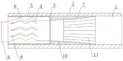
Fig. 1 is a schematic diagram of a noise reduction type air duct structure of a variable-frequency constant-temperature constant-humidity fresh air machine.
The reference numerals are explained below:
1. an air duct body; 2. an outer sound insulating coating layer; 3. a partition plate; 4. resistive folded plates; 5. a smooth surface reflective layer; 6. a partition wall; 7. inner silencing cotton; 8. an air inlet connecting pipe; 9. a folded plate shunt drag reduction head; 10. a flow equalizing cross post; 11. a reduced pressure chamber column.
Detailed Description
In the description of the present invention, it is to be understood that the terms "center", "longitudinal", "lateral", "up", "down", "front", "back", "left", "right", "vertical", "horizontal", "top", "bottom", "inner", "outer", and the like, indicate orientations or positional relationships based on the orientations or positional relationships shown in the drawings, and are used merely for convenience of description and for simplicity of description, and do not indicate or imply that the device or element being referred to must have a particular orientation, be constructed and operated in a particular orientation, and therefore, should not be construed as limiting the present invention. Furthermore, the terms "first", "second", etc. are used for descriptive purposes only and are not to be construed as indicating or implying relative importance or implicitly indicating the number of technical features indicated. Thus, a feature defined as "first," "second," etc. may explicitly or implicitly include one or more of that feature. In the description of the present invention, "a plurality" means two or more unless otherwise specified.
In the description of the present invention, it is to be noted that, unless otherwise explicitly specified or limited, the terms "mounted," "connected," and "connected" are to be construed broadly, and may be, for example, fixedly connected, detachably connected, or integrally connected; can be mechanically or electrically connected; they may be connected directly or indirectly through intervening media, or they may be interconnected between two elements. The specific meaning of the above terms in the present invention can be understood by those of ordinary skill in the art through specific situations.
The present invention will be further explained with reference to the accompanying drawings:
as shown in fig. 1, the muffling air duct structure of the variable-frequency constant-temperature and constant-humidity fresh air machine is composed of an air duct body 1, an outer sound insulation coating layer 2, an insulation plate 3, a resistive folded plate 4, a smooth surface reflecting layer 5, an interlayer wall 6 and inner sound insulation cotton 7;
a partition plate 3 is vertically arranged in the air duct body 1 in a partitioned manner, the partition plate 3 divides the air duct body 1 into a resistive silencing pipeline and a partial pressure silencing pipeline, a partition wall 6 is arranged in the resistive silencing pipeline, a resistive folded plate 4 is fixedly arranged in the partition wall 6, a reflecting cavity is formed between the partition wall 6 and the inner side wall of the air duct body 1, and a smooth surface reflecting layer 5 is arranged in the reflecting cavity;
the inside fixed mounting of partial pressure amortization pipeline has the stull 10 that flow equalizes, installs on the stull 10 and is fixed with decompression chamber post 11.
In this embodiment, the cladding has outer sound insulation coating 2 to be used for separating the interior a small amount of noises that spread on the lateral surface of wind channel body 1, and the installation of one side of interlayer wall 6 is fixed with admits air and takes over 8 and be used for inserting new trend system.
In this embodiment, form the sound insulation gap between the inside wall of the horizontal post 10 that flow equalizes, decompression chamber post 11 and wind channel body 1, the sound insulation gap is filled with in-house amortization cotton 7.
In the embodiment, the smooth surface reflecting layer 5 is attached to the inner side wall of the resistive noise reduction pipeline, and an interlayer inner pipe formed by the interlayer wall 6 is communicated with the flow equalizing cross column 10.
In this embodiment, the inside of the flow equalizing cross post 10 is provided with a flow equalizing hole, the inside of the pressure reducing cavity post 11 is provided with a pressure reducing cavity hole, and the aperture of one end of the pressure reducing cavity hole close to the flow equalizing cross post 10 is smaller than that of the other end.
In this embodiment, resistive folded plate 4 comprises a plurality of resistive plate, the interval is equipped with 135 degrees between the resistive plate, keeps away from on resistive folded plate 4 to separate the one end fixed mounting who establishes board 3 and have folded plate reposition of redundant personnel drag reduction head 9, and folded plate reposition of redundant personnel drag reduction head 9 is used for reducing the windage for the conical head.
In the structure, after fresh air enters the resistive folded plate, the following sound waves are partially offset with the front waves under the multi-stage resistive reflection of the folded plate, meanwhile, a part of the sound waves enter the reflection cavity through the partition wall 6 to be consumed in the reflection process, meanwhile, the air flow enters the decompression cavity column 10 from the flow equalizing cross column, the total aperture is enlarged, and a small amount of sound waves in the transmission process are consumed by the inner layer of soundproof cotton and the outer layer of soundproof cotton.
The foregoing illustrates and describes the principles, general features, and advantages of the present invention. It will be understood by those skilled in the art that the present invention is not limited to the above embodiments, and that the foregoing embodiments and descriptions are provided only to illustrate the principles of the present invention without departing from the spirit and scope of the present invention. The scope of the invention is defined by the appended claims and equivalents thereof.
Claims (6)

1.一种变频恒温恒湿新风机的消音式风道结构,其特征在于:包括风道管体、外隔音包覆层、隔设板、阻性折板、光面反射层、隔层壁和内消音棉,所述风道管体的管体内部竖直隔设有所述隔设板,所述隔设板将所述风道管体隔设为阻性消音管道和分压消音管道,所述阻性消音管道的内部安装有所述隔层壁,所述隔层壁的内部固定安装有所述阻性折板,所述隔层壁和所述风道管体的内侧壁之间形成反射腔,所述反射腔内设置有所述光面反射层,所述分压消音管道的内部固定安装有均流横柱,所述均流横柱上安装固定有减压腔柱。1. a noise-absorbing air duct structure of a variable frequency constant temperature and humidity fresh air blower, is characterized in that: comprising an air duct pipe body, an outer sound insulation coating, a partition board, a resistive folding plate, a glossy reflective layer, a partition wall And the inner sound-absorbing cotton, the interior of the air duct pipe body is vertically separated with the partition plate, and the partition plate separates the air duct pipe body into a resistive sound-absorbing pipe and a partial pressure sound-absorbing pipe , the interior of the resistive muffler pipe is installed with the partition wall, the interior of the partition wall is fixedly installed with the resistive folded plate, the partition wall and the inner side wall of the air duct pipe body are installed A reflection cavity is formed between the reflection cavity, the smooth surface reflection layer is arranged in the reflection cavity, a flow equalizing column is fixedly installed in the interior of the partial pressure sound-absorbing pipe, and a decompression cavity column is installed and fixed on the current equalizing transverse column. 2.根据权利要求1所述的一种变频恒温恒湿新风机的消音式风道结构,其特征在于:所述风道管体的外侧面上包覆有所述外隔音包覆层用于隔设内部传出的少量噪音,所述隔层壁的一侧安装固定有进气接管用于接入新风系统。2. The noise-absorbing air duct structure of a variable frequency constant temperature and humidity fresh fan according to claim 1, characterized in that: the outer surface of the air duct pipe body is covered with the outer sound insulation coating for use in A small amount of noise from the inside is isolated, and an air intake pipe is installed and fixed on one side of the partition wall for connecting to the fresh air system. 3.根据权利要求1所述的一种变频恒温恒湿新风机的消音式风道结构,其特征在于:所述均流横柱、所述减压腔柱和所述风道管体的内侧壁之间形成隔音缝隙,所述隔音缝隙内塞设有所述内消音棉。3. The noise-absorbing air duct structure of a variable frequency constant temperature and humidity fresh air blower according to claim 1, characterized in that: the inner side of the flow equalizing column, the decompression cavity column and the air duct pipe body A sound-insulating gap is formed between the walls, and the inner sound-absorbing cotton is plugged in the sound-insulating gap. 4.根据权利要求1所述的一种变频恒温恒湿新风机的消音式风道结构,其特征在于:所述光面反射层贴覆安装到所述阻性消音管道的内侧壁上,所述隔层壁所形成的隔层内管与所述均流横柱连通在一起。4. The noise-absorbing air duct structure of a variable-frequency constant-temperature and constant-humidity fresh fan according to claim 1, characterized in that: the glossy reflection layer is attached and installed on the inner wall of the resistive noise-absorbing pipe, so that the The interlayer inner tube formed by the interlayer wall is communicated with the flow-equalizing transverse column. 5.根据权利要求1所述的一种变频恒温恒湿新风机的消音式风道结构,其特征在于:所述均流横柱的内部设置有均流孔,所述减压腔柱的内部开设有减压腔孔,所述减压腔孔上靠近所述均流横柱的一端孔径小于另一端孔径。5. The noise-absorbing air duct structure of a variable frequency constant temperature and humidity fresh air blower according to claim 1, characterized in that: the interior of the equalizing horizontal column is provided with an equalizing hole, and the interior of the decompression cavity column is provided with an equalizing hole. A decompression cavity hole is opened, and the diameter of one end of the decompression cavity hole close to the flow-equalizing transverse column is smaller than that of the other end. 6.根据权利要求1所述的一种变频恒温恒湿新风机的消音式风道结构,其特征在于:所述阻性折板由若干个阻性板组成,所述阻性板之间隔设有135度,所述阻性折板上远离所述隔设板的一端固定安装有折板分流减阻头,所述折板分流减阻头为锥头用于减少风阻。6. The noise-absorbing air duct structure of a variable frequency constant temperature and humidity fresh fan according to claim 1, wherein the resistive folded plate is composed of several resistive plates, and the resistive plates are spaced apart from each other. There is a 135-degree angle, and one end of the resistive folded plate away from the partition plate is fixedly installed with a folded plate shunt and drag reduction head, and the folded plate shunt and drag reduction head is a cone head for reducing wind resistance.
CN202020843847.7U 2020-05-20 2020-05-20 A noise-absorbing air duct structure of a variable frequency constant temperature and humidity fresh fan Expired - Fee Related CN212378212U (en)

Priority Applications (1)

Application Number Priority Date Filing Date Title
CN202020843847.7U CN212378212U (en) 2020-05-20 2020-05-20 A noise-absorbing air duct structure of a variable frequency constant temperature and humidity fresh fan

Applications Claiming Priority (1)

Application Number Priority Date Filing Date Title
CN202020843847.7U CN212378212U (en) 2020-05-20 2020-05-20 A noise-absorbing air duct structure of a variable frequency constant temperature and humidity fresh fan

Publications (1)

Publication Number Publication Date
CN212378212U true CN212378212U (en) 2021-01-19

Family

ID=74176921

Family Applications (1)

Application Number Title Priority Date Filing Date
CN202020843847.7U Expired - Fee Related CN212378212U (en) 2020-05-20 2020-05-20 A noise-absorbing air duct structure of a variable frequency constant temperature and humidity fresh fan

Country Status (1)

Country Link
CN (1) CN212378212U (en)

Cited By (1)

* Cited by examiner, † Cited by third party
Publication number Priority date Publication date Assignee Title
CN113932084A (en) * 2021-09-30 2022-01-14 浙江纳风净化技术有限公司 Hole diameter adjusting type silencing pipe

Cited By (1)

* Cited by examiner, † Cited by third party
Publication number Priority date Publication date Assignee Title
CN113932084A (en) * 2021-09-30 2022-01-14 浙江纳风净化技术有限公司 Hole diameter adjusting type silencing pipe

Similar Documents

Publication Publication Date Title
CN201230860Y (en) Dust collector with silencing structure
WO2005018404A1 (en) A noise-reducing unit for a vacuum cleaner
CN104948265A (en) Impedance compound muffler
CN104747856A (en) Wind pipe noise reducing structure, wind pipe and wind pipe type air conditioner
CN206207705U (en) The muffler and air-conditioning of a kind of air-conditioning
CN206319975U (en) Engine overhead air filter
CN201262108Y (en) Resistive sheet type silencer
WO2020125046A1 (en) Magnetic suspension centrifugal fan cabinet
CN202047880U (en) Novel impedance composite silencer
CN201953444U (en) Silencer
CN206917701U (en) Exhaust silencer and gas extraction system
CN206487543U (en) A kind of diesel-driven generator exhaust silencer system
CN205895606U (en) High -efficient silencing device of multilayer
CN216278679U (en) Low-frequency silencer in centrifugal fan
CN216203628U (en) Exhaust pipe and lampblack absorber subassembly
CN206617215U (en) A kind of MPV exhaust silencer devices
CN109404345A (en) A kind of air inlet noise-reducing structure of magnetic suspension blower
CN112046222A (en) Self-cleaning silencer for air intake and exhaust system of air suspension
CN204253153U (en) A kind of internal combustion locomotive impedance composite muffler
CN212407945U (en) Exhaust silencer
CN115596920A (en) Resistive silencer of super-structure piece formula
CN210919583U (en) Noise eliminator for blower
CN210602201U (en) A silent rectifier static pressure box structure for combined air conditioner
CN218074833U (en) Silencers and Wall Climbing Robots
CN114215707A (en) Noise eliminator and wind generating set

Legal Events

Date Code Title Description
GR01 Patent grant
GR01 Patent grant
CF01 Termination of patent right due to non-payment of annual fee

Granted publication date: 20210119

CF01 Termination of patent right due to non-payment of annual fee