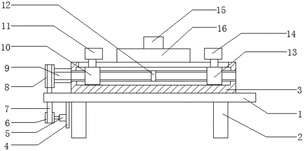
Positioning device for assembling slewing bearing
Technical Field
The utility model relates to a slewing bearing technical field specifically is a positioner for slewing bearing equipment.
Background
After each part of the slewing bearing is machined, the slewing bearing needs to be assembled, and a positioning device needs to be used for positioning the bearing in the assembling process. The existing positioning device only positions and fixes the outer ring of the bearing, the existing positioning device avoids damaging the surface of the bearing, a layer of rubber pad is added, the rubber pad is large in telescopic type, and the positioning device is enabled to deviate in the positioning process of the bearing, so that the assembly precision of the bearing is influenced. To this end, we propose a positioning device for the assembly of a slew bearing.
SUMMERY OF THE UTILITY MODEL
An object of the utility model is to provide a positioner for slew bearing equipment to solve the problem that proposes among the above-mentioned background art.
In order to achieve the above object, the utility model provides a following technical scheme: a positioning device for assembling a slewing bearing comprises a supporting platform, wherein a supporting column is arranged at the bottom of the supporting platform, a fixed frame is arranged at the top of the supporting platform, a fixed plate is arranged at the left end of the bottom of the supporting platform, a motor is arranged on the left side surface of the fixed plate, a first belt wheel is arranged at the left end of the motor, a belt is connected to the surface of the first belt wheel, a second belt wheel is connected to the top of the belt, a lead screw is arranged at the right end of the second belt wheel, a limiting block is arranged in the middle of the lead screw, a first sliding block is arranged on the left side of the surface of the lead screw, a left positioning block is arranged at the top of the first sliding block and comprises a first clamping block, an upper clamping block is arranged at the top of the first clamping block, a lower clamping block is arranged at the bottom of the first clamping block, and the upper clamping block, the left end of first clamp splice is provided with telescopic cylinder, both ends all are provided with the connecting block about the telescopic cylinder left side, the bottom of connecting block is connected with the connecting rod, the bottom of connecting rod is provided with the fixed block, the surperficial right side of lead screw is provided with the second slider, the top of second slider is provided with right locating piece, the top of mount is provided with the reference column, the surface of reference column is provided with slewing bearing.
Preferably, two sets of moving blocks are arranged in the middle of the positioning column, a baffle is arranged in the middle of the moving blocks, a spring is arranged at the left end of the baffle, a lifting block is arranged between the two sets of moving blocks, a threaded rod is arranged at the top of the lifting block, and a threaded sleeve is arranged in the middle of the threaded rod.
Preferably, the limiting block supports the lead screw, and the thread turning directions of the surfaces of the lead screw on the left side and the right side of the limiting block are opposite.
Preferably, a shaft sleeve is arranged at the joint of the right end of the lead screw and the fixing frame.
Preferably, the right end of the telescopic cylinder is welded on the left side surface of the first clamping block.
Preferably, the upper end and the lower end of the connecting rod are movably connected with the bottom of the telescopic cylinder and the fixing block.
Compared with the prior art, the beneficial effects of the utility model are that:
1. through setting the locating piece to three parts, carrying out the location to the bearing of different diameters and pressing from both sides tightly, avoiding changing anchor clamps, guarantee simultaneously with the area of contact of bearing inner race, avoid the bearing because locating piece area of contact is less, the too big surface to the bearing of pressure causes the damage.
2. The left positioning block and the right positioning block can fix the outer ring of the slewing bearing in a positioning mode, the positioning columns fix the inner ring of the bearing in a positioning mode, balls and the ball retainer are installed quickly, and installation accuracy of the balls and the ball retainer can be guaranteed.
Drawings
FIG. 1 is a schematic structural view of the present invention;
FIG. 2 is a schematic view of the positioning block of the present invention;
fig. 3 is a schematic view of the positioning column of the present invention.
In the figure: the device comprises a supporting platform 1, a supporting column 2, a fixing frame 3, a fixing plate 4, a motor 5, a first belt wheel 6, a belt 7, a second belt wheel 8, a screw rod 9, a first sliding block 10, a left positioning block 11, a first clamping block 111, an upper clamping block 112, a lower clamping block 113, a pin shaft 114, a telescopic cylinder 115, a connecting block 116, a connecting rod 117, a fixed block 118, a limited block 12, a second sliding block 13, a right positioning block 14, a positioning column 15, a moving block 151, a baffle 152, a spring 153, a lifting block 154, a threaded rod 155, a threaded sleeve 156 and a rotary bearing 16.
Detailed Description
The technical solutions in the embodiments of the present invention will be described clearly and completely with reference to the accompanying drawings in the embodiments of the present invention, and it is obvious that the described embodiments are only some embodiments of the present invention, not all embodiments. Based on the embodiments in the present invention, all other embodiments obtained by a person skilled in the art without creative work belong to the protection scope of the present invention.
Referring to fig. 1-3, the present invention provides a technical solution: a positioning device for assembling a rotary bearing comprises a supporting platform 1, a supporting column 2 is arranged at the bottom of the supporting platform 1, a fixed frame 3 is arranged at the top of the supporting platform 1, a fixed plate 4 is arranged at the left end of the bottom of the supporting platform 1, a motor 5 is arranged on the left side surface of the fixed plate 4, a first belt wheel 6 is arranged at the left end of the motor 5, a belt 7 is connected to the surface of the first belt wheel 6, a second belt wheel 8 is connected to the top of the belt 7, a lead screw 9 is arranged at the right end of the second belt wheel 8, a limit block 12 is arranged in the middle of the lead screw 9, a first slider 10 is arranged on the left side of the surface of the lead screw 9, a left positioning block 11 is arranged at the top of the first slider 10, the motor 5 is started, the first belt wheel 6 is driven by the motor 5 to rotate, the, the left and right thread turning directions of the screw 9 are opposite, so that the first slider 10 and the second slider 13 move oppositely, the outer ring of the rotary bearing 16 is clamped and positioned, the left positioning block 11 comprises a first clamping block 111, an upper clamping block 112 is arranged at the top of the first clamping block 111, a lower clamping block 113 is arranged at the bottom of the first clamping block 111, the upper clamping block 112 and the lower clamping block 113 are both connected with the first clamping block 111 through a pin 114, a telescopic cylinder 115 is arranged at the left end of the first clamping block 111, connecting blocks 116 are arranged at the upper and lower ends of the left side of the telescopic cylinder 115, the bottom end of the connecting block 116 is connected with a connecting rod 117, a fixing block 118 is arranged at the bottom end of the connecting rod 117, when the positioning block 11 positions and clamps the outer ring of the bearing, the first clamping block 111 firstly contacts the outer ring of the bearing, at the moment, the rotation of the motor 5 is stopped, the telescopic cylinder 115 drives the connecting block 116, the connecting, go up clamp splice 112 and lower clamp splice 113 and rotate through round pin axle 114, fix a position the outer wall to slewing bearing and press from both sides tightly, through setting the locating piece into the three, fix a position the bearing to different diameters and press from both sides tightly, guarantee with the area of contact of bearing inner race, avoid the bearing because locating piece area of contact is less, pressure causes the damage to the surface of bearing too big, the surperficial right side of lead screw 9 is provided with second slider 13, the top of second slider 13 is provided with right locating piece 14, the top of mount 3 is provided with reference column 15, the surface of reference column 15 is provided with slewing bearing 16.
Wherein, two sets of moving blocks 151 are arranged in the middle of the positioning column 15, a baffle 152 is arranged in the middle of the moving blocks 151, a spring 153 is arranged at the left end of the baffle 152, a lifting block 154 is arranged between the two sets of moving blocks 151, a threaded rod 155 is arranged on the top of the lifting block 154, a threaded sleeve 156 is arranged in the middle of the threaded rod 155, when the inner ring of the bearing is fixed,
the threaded rod 155 is rotated, the threaded rod 155 interacts with the threaded sleeve 156 to move downwards, so that the lifting block 154 moves downwards, and the lifting block 154 pushes the two groups of moving blocks 151 to move towards two sides to position and fix the inner ring of the bearing because the width of the bottom of the lifting block 154 is smaller than that of the top of the lifting block;
the limiting block 12 supports the screw rod 9, and the screw threads on the surfaces of the screw rod 9 on the left side and the right side of the limiting block 12 are opposite in rotation direction, so that the screw rod 9 enables the positioning block 11 and the right positioning block 14 to move relatively in the rotation process, and the bearing outer ring is positioned and clamped;
a shaft sleeve is arranged at the joint of the right end of the lead screw 9 and the fixed frame 3, so that the friction force between the end part of the lead screw 9 and the fixed frame 3 is reduced;
the right end of the telescopic cylinder 115 is welded on the left side surface of the first clamping block 111;
the upper end and the lower end of the connecting rod 117 are movably connected with the bottom of the telescopic cylinder 115 and the fixed block 118.
The working principle is as follows: when the slewing bearing needs to be assembled, the motor 5 is started, the motor 5 drives the first belt pulley 6 to rotate, the first belt pulley 6 drives the second belt pulley 8 to rotate through the belt 7, the second belt pulley 8 drives the lead screw 9 to rotate, the thread turning directions of the left side and the right side of the lead screw 9 are opposite, the first sliding block 10 and the second sliding block 13 move oppositely, the outer ring of the slewing bearing 16 is clamped and positioned, when the positioning block 11 positions and clamps the outer ring of the bearing, the first clamping block 111 firstly contacts the outer ring of the bearing, at the moment, the rotation of the motor 5 is stopped, the telescopic cylinder 115 drives the connecting block 116 to move rightwards, the connecting block 116 pushes the upper clamping block 112 and the lower clamping block 113 rightwards through the connecting rod 117, the upper clamping block 112 and the lower clamping block 113 rotate through the pin shaft 114, the outer wall of the slewing bearing is positioned and clamped, the positioning blocks are arranged into three parts, and the bearings, the area of contact with the bearing inner race is guaranteed, avoid the bearing because locating piece area of contact is less, pressure is too big to cause the damage to the surface of bearing, the threaded rod 155 rotates, threaded rod 155 is through interacting with threaded sleeve 156, move down, make elevator 154 move down, because elevator 154 bottom width is less than the top width, so the elevator 154 promotes two sets of movable blocks 151 and moves to both sides, fix a position the inner circle of bearing fixedly, fix a position through the inner and outer lane of multiaxis and hold, make ball and ball holder install fast, and can guarantee ball and ball holder's installation accuracy.
Although embodiments of the present invention have been shown and described, it will be appreciated by those skilled in the art that changes, modifications, substitutions and alterations can be made in these embodiments without departing from the principles and spirit of the invention, the scope of which is defined in the appended claims and their equivalents.