CN212370931U - Edge trimmer with effect of quickly removing waste materials - Google Patents
Edge trimmer with effect of quickly removing waste materials Download PDFInfo
- Publication number
- CN212370931U CN212370931U CN202020599161.8U CN202020599161U CN212370931U CN 212370931 U CN212370931 U CN 212370931U CN 202020599161 U CN202020599161 U CN 202020599161U CN 212370931 U CN212370931 U CN 212370931U
- Authority
- CN
- China
- Prior art keywords
- box body
- box
- telescopic
- rod
- mould
- Prior art date
- Legal status (The legal status is an assumption and is not a legal conclusion. Google has not performed a legal analysis and makes no representation as to the accuracy of the status listed.)
- Active
Links
- 239000002699 waste material Substances 0.000 title claims abstract description 19
- 230000000694 effects Effects 0.000 title claims abstract description 9
- 238000009966 trimming Methods 0.000 claims abstract description 20
- 238000004140 cleaning Methods 0.000 claims abstract description 8
- XLYOFNOQVPJJNP-UHFFFAOYSA-N water Substances O XLYOFNOQVPJJNP-UHFFFAOYSA-N 0.000 claims description 21
- 238000005507 spraying Methods 0.000 claims description 6
- 238000005520 cutting process Methods 0.000 abstract description 9
- 239000011324 bead Substances 0.000 abstract description 4
- 238000004519 manufacturing process Methods 0.000 abstract description 3
- 238000009826 distribution Methods 0.000 abstract description 2
- 239000007921 spray Substances 0.000 description 9
- XEEYBQQBJWHFJM-UHFFFAOYSA-N Iron Chemical compound [Fe] XEEYBQQBJWHFJM-UHFFFAOYSA-N 0.000 description 8
- 238000009825 accumulation Methods 0.000 description 4
- 229910052742 iron Inorganic materials 0.000 description 4
- 239000000428 dust Substances 0.000 description 3
- 238000003825 pressing Methods 0.000 description 2
- 229910000831 Steel Inorganic materials 0.000 description 1
- 230000004075 alteration Effects 0.000 description 1
- 230000002337 anti-port Effects 0.000 description 1
- 230000009286 beneficial effect Effects 0.000 description 1
- 125000004122 cyclic group Chemical group 0.000 description 1
- 230000008595 infiltration Effects 0.000 description 1
- 238000001764 infiltration Methods 0.000 description 1
- 238000012986 modification Methods 0.000 description 1
- 230000004048 modification Effects 0.000 description 1
- 239000002994 raw material Substances 0.000 description 1
- 238000011084 recovery Methods 0.000 description 1
- 239000010959 steel Substances 0.000 description 1
- 238000006467 substitution reaction Methods 0.000 description 1
Images


Landscapes
- Cleaning In General (AREA)
Abstract
The utility model discloses a bead cutter with get rid of waste material effect fast, the power distribution box comprises a box body, the middle top of box is equipped with flexible motor, the output of flexible motor is the telescopic link, the telescopic link runs through the box top and gos deep into the inside and fixedly connected with of box and cut edge the mould, the below of cutting edge the mould is equipped with down the side cut mould, the top of cutting edge the mould down is equipped with flexible rotatory brush, the below of cutting edge the mould down is equipped with unable adjustment base, unable adjustment base top both sides are to the downside setting, unable adjustment base outmost edge both sides are equipped with the sweeps pipeline, the bottom of sweeps pipeline is equipped with album bits case. The utility model has the advantages that: the in-time cleaning of sweeps on the die can be realized, the removal of wastes and the trimming are completed at the same time, the dangerous operation of removing the wastes by hands of workers is avoided, the time cost for removing the wastes is saved, and the production efficiency is improved.
Description
Technical Field
The utility model belongs to the technical field of the bead cutter, concretely relates to bead cutter with get rid of waste material effect fast.
Background
After the track iron teeth are connected through rubber, the track iron teeth are generally used as track wheels of an excavator or agricultural machinery, when the track iron teeth are forged, blanks are manufactured after the steel raw material is smelted, the blanks are formed through a press, and the formed track iron teeth can be machined after edge cutting treatment. The pneumatic cylinder on the edge trimmer drives the lower pressing seat to press down rapidly, so that the male die below the lower pressing seat is used for trimming the workpiece in the female die. After the work piece was handled by the side cut, the waste material that cuts off is continuous piles up in the left and right sides of die, and the pressfitting height of seat is pressed down in order to avoid influencing because piling up of waste material is too high, often needs the manual work to carry out manual processing to the waste material, so, not only delay man-hour, more cost the manpower moreover, cause danger for the workman easily, finally influence workman's work efficiency.
SUMMERY OF THE UTILITY MODEL
In order to solve the above problem, the utility model provides a following technical scheme: the utility model provides a bead cutter with get rid of waste material effect fast, the power distribution box comprises a box body, the middle top of box is equipped with flexible motor, the output of flexible motor is the telescopic link, the telescopic link runs through the box top and gos deep into the inside and fixedly connected with of box and cut edge the mould, the below of cutting edge the mould is equipped with down the side cut mould, the top of cutting edge the mould down is equipped with flexible rotatory brush, flexible rotatory brush one end is connected with drive arrangement, drive arrangement fixes on the lateral wall of box, the below of cutting edge the mould is equipped with unable adjustment base down, unable adjustment base top both sides set up along the box inner wall to the bottom, unable adjustment base is equipped with the clear bits pipeline in the outmost edge both sides, the bottom of clear bits pipeline is equipped.
Further, drive arrangement includes supporting seat, rotating electrical machines, output pole and threaded rod, the supporting seat is fixed on the lateral wall of box, fixedly connected with rotating electrical machines in the supporting seat, be connected with two output poles on the rotating electrical machines, the threaded rod include stalk portion and with stalk portion fixed connection's pole portion, the stalk portion both sides all are equipped with the connecting hole, two output poles pass the connecting hole respectively and are connected with the threaded rod, pole portion surface be equipped with the screw thread and run through the box lateral wall with flexible rotatory brush is connected, the lateral wall is by the fixed nut that is equipped with the cooperation threaded rod of part that pole portion runs through.
Further, the inside top of box is equipped with the fan, the fan openly faces down.
Furthermore, a water spraying pipe is further arranged on the inner wall of the box body, and the water spraying pipe is obliquely arranged below the telescopic rotating rod.
Furthermore, the bottom of the scrap collecting box is composed of a filter screen, and a water accumulating box is arranged below the scrap collecting box.
Furthermore, the chip collecting box and the water accumulating box are respectively provided with a handle convenient to pull.
The utility model has the advantages that:
1. the in-time cleaning of sweeps on the die can be realized, the removal of wastes and the trimming are completed at the same time, the dangerous operation of removing the wastes by hands of workers is avoided, the time cost for removing the wastes is saved, and the production efficiency is improved.
2. Can reduce the dirt bits through being equipped with the spray pipe in this application and fly upward, further promote the clearance effect, set up filter screen and water accumulation case in the bottom of collection bits case simultaneously, can the water recovery resource, realize the cyclic utilization of water resource.
Drawings
Fig. 1 is a schematic structural view of the present invention;
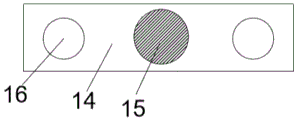
FIG. 2 is a schematic view of a threaded rod configuration;
FIG. 3 is a schematic view of the threaded rod with the rod portion facing upward;
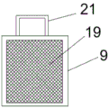
FIG. 4 is a schematic view of the structure of the chip collecting box.
In the figure: 1. a box body; 2. a telescopic motor; 3. a telescopic rod; 4. an upper trimming die; 5. a lower trimming die; 6. a telescopic rotary brush; 7. a fixed base; 8. a scrap removal pipeline; 9. a scrap collecting box; 10. a supporting seat; 11. a rotating electric machine; 12. an output rod; 13. a threaded rod; 14. a handle; 15. a rod portion; 16. connecting holes; 17. a fan; 18. a water spray pipe; 19. a filter screen; 20. a water accumulation tank; 21. a handle.
Detailed Description
The technical solution in the embodiments of the present invention will be clearly and completely described below with reference to the accompanying drawings in the embodiments of the present invention.
Referring to fig. 1-4, a trimming machine with a rapid waste material removing effect comprises a box body 1, a telescopic motor 2 is arranged at the middle top of the box body 1, an output end of the telescopic motor 2 is a telescopic rod 3, the telescopic rod 3 penetrates through the top of the box body 1 to penetrate into the box body 1 and is fixedly connected with an upper trimming die 4, a lower trimming die 5 is arranged below the upper trimming die 4, a telescopic rotary brush 6 is arranged above the lower trimming die 5, one end of the telescopic rotary brush 6 is connected with a driving device, the driving device comprises a supporting seat 10, a rotary motor 11, output rods 12 and a threaded rod 13, the supporting seat 10 is fixed on the outer side wall of the box body 1, the rotary motor 11 is fixedly connected in the supporting seat 10, the rotary motor 11 is connected with two output rods 12, the threaded rod 13 comprises a handle portion 14 and a rod portion 15 fixedly connected with the handle portion 14, the 14 both sides of stalk portion all are equipped with connecting hole 16, two output rod 12 pass connecting hole 16 respectively and are connected with threaded rod 13, 15 surfaces in pole portion be equipped with the screw thread and run through 1 lateral wall of box with flexible rotatory brush 6 is connected, the part that the lateral wall was run through by pole portion 15 is fixed and is equipped with the nut (not shown in the picture) of cooperation threaded rod 13, the below of cutting edge mould 5 is equipped with unable adjustment base 7 down, unable adjustment base 7 top both sides set up along 1 inside wall of box downwards to one side, and the slant sets up the sweeps that can assist on cutting edge mould 5 down and falls into unable adjustment base 7's both sides, unable adjustment base 7 is equipped with clear bits pipeline 8 in the outermost edge both sides, the bottom of clear bits pipeline 8 is equipped with collection bits. The bottom of collection bits case 9 comprises filter screen 19, the below of collection bits case 9 is equipped with water accumulation box 20, all be equipped with the handle 21 of the pull of being convenient for on collection bits case 9 and the water accumulation box 20, the inside top of box 1 is equipped with fan 17, and fan 17 is equipped with two altogether, and the symmetry sets up the inboard top at box 1, fan 17 openly faces down, and cooperation unable adjustment base 7 blows in the clearance passageway to the sweeps to the structure that both sides set up to the slant, still be equipped with spray pipe 18 on the inner wall of box 1, spray pipe 18 is put to one side the below of flexible rotary rod, spray pipe 18 can spray water on flexible rotary brush 6 and the mould, both can clear up flexible rotary brush 6, also can prevent the circumstances that the dirt bits fly upward. The telescopic rotating brush 6, the driving device and the water spraying pipe 18 in the embodiment are respectively and symmetrically arranged on two sides of the box body 1, so that the cleaning effect can be better achieved.
The use principle of the embodiment is as follows; after the upper trimming die 4 is driven by the telescopic motor 2 to trim the product on the lower trimming die 5, the rotary motor 11 is driven to drive the two output rods 12 to rotate in the forward direction, the output rods 12 drive the threaded rod 13 to rotate, the threaded rod 13 is matched with a nut (not shown in the figure) in the side wall of the box body to move rightwards, the telescopic rotary brush 6 is driven to rotate and move upwards the die, the scraps accumulated on the lower trimming die 5 are cleaned by the bristles on the telescopic rotary brush 6, the scraps are cleaned from the lower trimming die 5, meanwhile, the fan 17 is driven to rotate and spray water by the water spray pipe 18, the fan 17 blows the scraps to the scrap cleaning pipelines 8 on two sides by wind power, the water spray pipe 18 can prevent the dust from flying up when the telescopic brush 6 is cleaned, and some dust with small volume can float up when being cleaned, and can drop down when spraying water to the dust and slide into the cleaning pipeline below, after finishing the clearance, drive threaded rod 13 through 11 antiport of rotating electrical machines and reset, collection bits case 9 can collect the sweeps, and unnecessary moisture passes through filter screen 19 infiltration ponding case 20 in the sweeps simultaneously, and the beneficial effect of this embodiment is: the in-time cleaning of sweeps on the die can be realized, the removal of wastes and the trimming are completed at the same time, the dangerous operation of removing the wastes by hands of workers is avoided, the time cost for removing the wastes is saved, and the production efficiency is improved.
Although embodiments of the present invention have been shown and described, it will be appreciated by those skilled in the art that changes, modifications, substitutions and alterations can be made in these embodiments without departing from the principles and spirit of the invention, the scope of which is defined in the appended claims and their equivalents.
Claims (6)
1. The utility model provides an edge trimmer with quick removal waste material effect which characterized in that: comprises a box body (1), a telescopic motor (2) is arranged at the top of the middle of the box body (1), the output end of the telescopic motor (2) is a telescopic rod (3), the telescopic rod (3) penetrates through the top of the box body (1) to penetrate into the box body (1) and is fixedly connected with an upper trimming die (4), a lower trimming die (5) is arranged below the upper trimming die (4), a telescopic rotary brush (6) is arranged above the lower trimming die (5), one end of the telescopic rotary brush (6) is connected with a driving device which is fixed on the outer side wall of the box body (1), a fixed base (7) is arranged below the lower trimming die (5), two sides of the top of the fixed base (7) are obliquely and downwards arranged along the inner side wall of the box body (1), and chip cleaning pipelines (8) are arranged on two sides of the outermost edge of the fixed base (7), and chip collecting boxes (9) are arranged at the bottoms of the chip cleaning pipelines (8).
2. Edge trimmer with quick scrap removal according to claim 1, characterized in that: the driving device comprises a supporting seat (10), a rotating motor (11), an output rod (12) and a threaded rod (13), the supporting seat (10) is fixed on the outer side wall of the box body (1), a rotating motor (11) is fixedly connected in the supporting seat (10), the rotating motor (11) is connected with two output rods (12), the threaded rod (13) comprises a handle part (14) and a rod part (15) fixedly connected with the handle part (14), both sides of the handle part (14) are provided with connecting holes (16), the two output rods (12) respectively penetrate through the connecting holes (16) to be connected with the threaded rod (13), the surface of the rod part (15) is provided with threads and penetrates through the side wall of the box body (1) to be connected with the telescopic rotary brush (6), and a nut matched with the threaded rod (13) is fixedly arranged on the part, penetrated by the rod part (15), of the side wall of the box body (1).
3. Edge trimmer with quick scrap removal according to claim 2, characterized in that: the top end of the interior of the box body (1) is provided with a fan (17), and the front face of the fan (17) faces downwards.
4. A trimmer with quick scrap removal according to claim 3, wherein: the inner wall of the box body (1) is also provided with a water spraying pipe (18), and the water spraying pipe (18) is obliquely arranged below the telescopic rotating rod.
5. Edge trimmer with quick scrap removal according to claim 4, characterized in that: the bottom of the scrap collecting box (9) is composed of a filter screen (19), and a water accumulating box (20) is arranged below the scrap collecting box (9).
6. Edge trimmer with fast scrap removal according to claim 5, characterized in that: the chip collecting box (9) and the water accumulating box (20) are respectively provided with a handle (21) which is convenient to draw.
Priority Applications (1)
| Application Number | Priority Date | Filing Date | Title |
|---|---|---|---|
| CN202020599161.8U CN212370931U (en) | 2020-04-21 | 2020-04-21 | Edge trimmer with effect of quickly removing waste materials |
Applications Claiming Priority (1)
| Application Number | Priority Date | Filing Date | Title |
|---|---|---|---|
| CN202020599161.8U CN212370931U (en) | 2020-04-21 | 2020-04-21 | Edge trimmer with effect of quickly removing waste materials |
Publications (1)
| Publication Number | Publication Date |
|---|---|
| CN212370931U true CN212370931U (en) | 2021-01-19 |
Family
ID=74160588
Family Applications (1)
| Application Number | Title | Priority Date | Filing Date |
|---|---|---|---|
| CN202020599161.8U Active CN212370931U (en) | 2020-04-21 | 2020-04-21 | Edge trimmer with effect of quickly removing waste materials |
Country Status (1)
| Country | Link |
|---|---|
| CN (1) | CN212370931U (en) |
Cited By (1)
| Publication number | Priority date | Publication date | Assignee | Title |
|---|---|---|---|---|
| CN112935121A (en) * | 2021-02-02 | 2021-06-11 | 赵园 | Auxiliary discharging device of die for stamping automobile parts |
-
2020
- 2020-04-21 CN CN202020599161.8U patent/CN212370931U/en active Active
Cited By (2)
| Publication number | Priority date | Publication date | Assignee | Title |
|---|---|---|---|---|
| CN112935121A (en) * | 2021-02-02 | 2021-06-11 | 赵园 | Auxiliary discharging device of die for stamping automobile parts |
| CN112935121B (en) * | 2021-02-02 | 2023-11-17 | 上海申驰实业股份有限公司 | Auxiliary discharging device of die for stamping automobile parts |
Similar Documents
| Publication | Publication Date | Title |
|---|---|---|
| CN203156839U (en) | Machining head with dust-absorbing device for clothes template machine | |
| CN212190775U (en) | Punching device for steel plate with recyclable waste | |
| CN219025780U (en) | Reinforcing steel bar cutting mechanism in electric power iron tower construction | |
| CN211662468U (en) | Sealing rubber pad trimming device for water pipe connection | |
| CN207431407U (en) | A kind of tubing automatic cutting device | |
| CN215848535U (en) | Gum material cuts dust collector | |
| CN213592432U (en) | Sheet metal part grinding device | |
| CN211760106U (en) | Automatic feeding equipment of numerical control machine tool | |
| CN210132646U (en) | Building material cutting device | |
| CN209954304U (en) | Iron scrap processing device for numerical control machining lathe | |
| CN214088281U (en) | Toughened glass cutting machine | |
| CN218425069U (en) | Die cutting die convenient to clean tool bit | |
| CN205571927U (en) | A workstation for milling machine | |
| CN217345614U (en) | Cutting device for plastic product excess material | |
| CN212021398U (en) | Trimming device for plastic products | |
| CN212189435U (en) | Numerical control lathe processing is with waste material chip removal device | |
| CN213003346U (en) | Laser cutting machine convenient to it is clean | |
| CN210160496U (en) | Gate type plate shearing machine | |
| CN217915531U (en) | A corrugated paper surface dust collector for corrugated paper production | |
| CN220516992U (en) | Scrap collecting device for production of steel wire mesh skeleton composite pipe | |
| CN212666228U (en) | Automatic waste removing device of splitting machine for processing racket handle skin | |
| CN223000200U (en) | Round steel peeler garbage collection device | |
| CN216939866U (en) | Deburring device for forging | |
| CN210079692U (en) | Punch press for recycling wind power blades | |
| CN216096727U (en) | Scrap collecting device of circular sawing machine |
Legal Events
| Date | Code | Title | Description |
|---|---|---|---|
| GR01 | Patent grant | ||
| GR01 | Patent grant |