CN212347893U - Brush type automatic backwashing filter - Google Patents
Brush type automatic backwashing filter Download PDFInfo
- Publication number
- CN212347893U CN212347893U CN202020285854.XU CN202020285854U CN212347893U CN 212347893 U CN212347893 U CN 212347893U CN 202020285854 U CN202020285854 U CN 202020285854U CN 212347893 U CN212347893 U CN 212347893U
- Authority
- CN
- China
- Prior art keywords
- brush
- filter
- water inlet
- pipe
- inlet pipe
- Prior art date
- Legal status (The legal status is an assumption and is not a legal conclusion. Google has not performed a legal analysis and makes no representation as to the accuracy of the status listed.)
- Active
Links
- 238000011001 backwashing Methods 0.000 title claims abstract description 14
- XLYOFNOQVPJJNP-UHFFFAOYSA-N water Substances O XLYOFNOQVPJJNP-UHFFFAOYSA-N 0.000 claims abstract description 41
- 230000007246 mechanism Effects 0.000 claims abstract description 15
- 238000009434 installation Methods 0.000 claims description 10
- 239000010865 sewage Substances 0.000 claims description 10
- 239000008187 granular material Substances 0.000 description 7
- 235000017166 Bambusa arundinacea Nutrition 0.000 description 4
- 235000017491 Bambusa tulda Nutrition 0.000 description 4
- 241001330002 Bambuseae Species 0.000 description 4
- 235000015334 Phyllostachys viridis Nutrition 0.000 description 4
- 239000011425 bamboo Substances 0.000 description 4
- 238000001914 filtration Methods 0.000 description 4
- 238000011010 flushing procedure Methods 0.000 description 3
- 238000000034 method Methods 0.000 description 3
- 238000013461 design Methods 0.000 description 2
- 238000012423 maintenance Methods 0.000 description 2
- 239000000463 material Substances 0.000 description 2
- 239000002245 particle Substances 0.000 description 2
- 230000008569 process Effects 0.000 description 2
- 238000007789 sealing Methods 0.000 description 2
- 238000013459 approach Methods 0.000 description 1
- 230000009286 beneficial effect Effects 0.000 description 1
- 230000005540 biological transmission Effects 0.000 description 1
- 230000008859 change Effects 0.000 description 1
- 239000003638 chemical reducing agent Substances 0.000 description 1
- 238000010586 diagram Methods 0.000 description 1
- 238000007599 discharging Methods 0.000 description 1
- 239000003814 drug Substances 0.000 description 1
- 230000003670 easy-to-clean Effects 0.000 description 1
- 235000013305 food Nutrition 0.000 description 1
- 239000012535 impurity Substances 0.000 description 1
- 230000007774 longterm Effects 0.000 description 1
- 238000005272 metallurgy Methods 0.000 description 1
- 238000005065 mining Methods 0.000 description 1
- 238000012986 modification Methods 0.000 description 1
- 230000004048 modification Effects 0.000 description 1
- 239000003208 petroleum Substances 0.000 description 1
- 230000009467 reduction Effects 0.000 description 1
- 239000000126 substance Substances 0.000 description 1
- 238000005406 washing Methods 0.000 description 1
Images



Landscapes
- Filtration Of Liquid (AREA)
Abstract
The utility model discloses a brush type automatic back washing filter in the technical field of back washing filters, which comprises a shell, wherein a water outlet pipe and a water inlet pipe are arranged on the shell, a water inlet pipe is sleeved in the water inlet pipe, a filter cartridge is arranged on the left side of the water inlet pipe, a blow-off pipe is arranged at the bottom of the filter cartridge, a top plate is arranged at the top of the filter cartridge, a cylinder is arranged at the top of the top plate, a telescopic rod is arranged below the cylinder, a brush mechanism is connected at the bottom of the telescopic rod, the brush mechanism comprises a disc, a square chute is arranged in the disc, a slide bar is connected in the square chute in a sliding way, and a fan-shaped brush is arranged on the slide bar. The wall of the filter cylinder can be better attached, and the filter cylinder is effectively clean.
Description
Technical Field
The utility model relates to a back flush filter technical field specifically is an automatic back flush filter of brush formula.
Background
The automatic back-flushing filter is widely used in the fields of metallurgy, chemical industry, petroleum, paper making, medicine, food, mining, electric power, urban water supply and the like. When the filter works, water to be filtered enters from the inlet and flows through the filter screen, particle impurities in the water are intercepted inside the filter screen, the filtered water is discharged from the outlet, more and more particles are intercepted on the filter screen after long-term use, the filtering speed is slowed down, when the pressure difference between the inlet and the outlet reaches a set value, the backwashing system is controlled to be started, water flow carries out reverse flushing on the filter screen, sewage is discharged from the sewage discharge outlet, after the filter screen is cleaned, the pressure difference is reduced to the minimum value, the system returns to the initial filtering state, and the system normally operates.
The coaxiality of a transmission shaft and a brush rod shaft in the existing speed reducer of the automatic backwashing filter is not easy to guarantee, the radial deflection of the brush rod is overlarge in the backwashing process, the sealing part fails to work, water leakage is caused, the maintenance is frequent, and the potential safety hazard is large.
Based on this, the utility model designs an automatic back flush filter of brush formula to solve above-mentioned problem.
SUMMERY OF THE UTILITY MODEL
An object of the utility model is to provide an automatic back flush filter of brush formula to solve the aforesaid at back flush in-process brush-holder stud radial beat too big, cause the seal part inefficacy to lead to leaking, the maintenance is frequent, the great problem of potential safety hazard.
In order to achieve the above object, the utility model provides a following technical scheme: the utility model provides an automatic back flush filter of brush formula, includes the casing, the casing left side is provided with the outlet pipe, the mouth of pipe of intaking has been seted up on the casing right side, the inlet tube has been cup jointed to the mouth of pipe inner wall of intaking, inlet tube left side end is provided with the cartridge filter, the cartridge filter bottom is provided with the blow off pipe, the cartridge filter top is provided with the roof, roof top center is provided with the cylinder, the cylinder below is provided with the telescopic link, the telescopic link bottom is connected with brush mechanism, brush mechanism includes the disc, be provided with a plurality of square spouts in the disc, the spring has been cup jointed to square spout inner wall, spring one end connect in square spout inner wall, the other end.
Preferably, the water outlet pipe and the water inlet pipe are respectively provided with a water outlet valve and a water inlet valve, and the sewage discharge pipe is provided with a sewage discharge valve.
Preferably, the fan-shaped hairbrush comprises a plurality of independent hairbrushes, the independent hairbrushes are arranged on the mounting rods, the mounting rods are hinged to each other, the mounting rods are hinged to the sliding rod on two sides, supporting rods are arranged on the upper side and the lower side of the mounting rods partially, and the supporting rods are connected with the upper side and the lower side of the disc in a sliding mode.
Preferably, the bottom of the shell is provided with a supporting leg, the middle part of the supporting leg is provided with a supporting disk, and the middle part of the supporting disk is sleeved with a drain pipe.
Preferably, the sewage draining pipe is provided with a baffle.
Preferably, the filter cartridge is a cone with a large upper part and a small lower part.
Compared with the prior art, the beneficial effects of the utility model are that: the utility model has reasonable structural design, on one hand, the air cylinder is matched with the telescopic rod for use, and the brush mechanism is controlled to move up and down to clean the filter screen in the back washing process, thereby avoiding the problem of water leakage caused by the failure of the sealing part due to the overlarge radial deflection of the brush rod; on the other hand, the brush mechanism is arranged to be telescopic, so that the brush can be better attached to the wall of the filtering cylinder, and the brush is effectively cleaned.
Drawings
In order to more clearly illustrate the technical solutions of the embodiments of the present invention, the drawings used in the description of the embodiments will be briefly introduced below, and it is obvious that the drawings in the following description are only some embodiments of the present invention, and it is obvious for those skilled in the art that other drawings can be obtained according to these drawings without creative efforts.
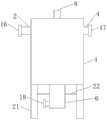
FIG. 1 is a first schematic structural diagram of the present invention;
FIG. 2 is a second schematic structural view of the present invention;
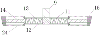
FIG. 3 is a schematic view of the brush mechanism of the present invention;
FIG. 4 is a top view of the brush mechanism of the present invention;
fig. 5 is a schematic view of the fan-shaped brush of the present invention.
In the drawings, the components represented by the respective reference numerals are listed below:
1. a housing; 2. a water outlet pipe; 3. a water inlet pipe orifice; 4. a water inlet pipe; 5. a filter cartridge; 6. a blow-off pipe; 7. a top plate; 8. a cylinder; 9. a telescopic rod; 10. a brush mechanism; 11. a disc; 12. a square chute; 13. a spring; 14. a slide bar; 15. a fan-shaped brush; 16. a water outlet valve; 17. a water inlet valve; 18. a blowoff valve; 19. an independent brush; 20. mounting a rod; 21. supporting legs; 22. a support disc; 23. a baffle plate; 24. a support rod.
Detailed Description
The technical solutions in the embodiments of the present invention will be described clearly and completely with reference to the accompanying drawings in the embodiments of the present invention, and it is obvious that the described embodiments are only some embodiments of the present invention, not all embodiments. Based on the embodiments of the present invention, all other embodiments obtained by a person of ordinary skill in the art without creative efforts belong to the protection scope of the present invention.
Referring to fig. 1-5, the present invention provides a technical solution: a brush type automatic back-flushing filter comprises a shell 1, wherein a water outlet pipe 2 is arranged on the left side of the shell 1, a water inlet pipe 3 is arranged on the right side of the shell 1, a water inlet pipe 4 is sleeved on the inner wall of the water inlet pipe 3, a filter cartridge 5 is arranged at the left side end of the water inlet pipe 4, a blow-off pipe 6 is arranged at the bottom of the filter cartridge 5, a top plate 7 is arranged at the top of the filter cartridge 5, an air cylinder 8 is arranged at the center of the top plate 7, an expansion link 9 is arranged below the air cylinder 8, a brush mechanism 10 is connected to the bottom of the expansion link 9, the brush mechanism 10 comprises a disc 11, a plurality of square chutes 12 are arranged in the disc 11, springs 13 are sleeved on the inner walls of the square chutes 12, one ends of the springs, the wall of the cylinder is cleaned.
Wherein, the outlet pipe 2 and the inlet pipe 4 are respectively provided with an outlet valve 16 and an inlet valve 17, the drain pipe 6 is provided with a drain valve 18 for controlling the movement of different water bodies, the fan-shaped brush 15 comprises a plurality of independent brushes 19, the independent brushes 19 are arranged on the installation rods 20, the installation rods 20 are hinged with each other, when the slide rod 14 stretches out and draws back, the radius of the fan-shaped brush 15 is changed, the hinged installation rods 20 can adjust the mutual distance, so that the fan-shaped brush 15 generates corresponding change, the installation rods 20 at two sides are hinged on the slide rod 14, the upper side and the lower side of part of the installation rods 20 are provided with support rods 24, the support rods 24 are connected with the upper side and the lower side of the disc 11 in a sliding way, the fan-shaped brush 15 is assisted in stable movement, the bottom of the shell 1 is provided with support legs 21 for supporting the device, be convenient for the installation and the stable placement of blow off pipe 6, be provided with baffle 23 on the blow off pipe 6, baffle 23 position is slightly less than casing 1, when baffle 23 closed, part granule can exist on baffle 23 through subsiding in the water, when carrying out the back flush, baffle 23 is opened, sewage discharging equipment is followed to the granule on the baffle 23, it is easy to clean, cartridge filter 5 is big-end-up's cone, can increase the effort of 5 water of entering cartridge filter to the cartridge filter wall, make on part granule falls into baffle 23 from the section of thick bamboo wall, reduce the granule and remain on the section of thick bamboo wall of cartridge filter 5, increase filtration efficiency.
One specific application of this embodiment is: when the inner diameter of the filter cartridge 5 is reduced, the filter cartridge 5 generates acting force on the fan-shaped brush 15, the fan-shaped brush 15 extrudes the sliding rod 14 to move towards the center of a circle, the sliding rod 14 slides in the square sliding groove 12, and simultaneously extrudes the spring 13 to deform the spring 13, meanwhile, the adjacent sliding rods 14 generate acting force on the mounting rods 20 to enable the mounting rods 20 to approach each other, the radius of the fan-shaped brush 15 is reduced along with the reduction of the filter cartridge 5, and similarly, when the inner diameter of the filter cartridge 5 is increased, the radius of the fan-shaped brush 15 is increased along with the increase of the filter cartridge 5, brush mechanism 10 cleans cartridge filter 5, make the granule on the section of thick bamboo wall not hard up, simultaneously through blowoff valve 18, the control water is from casing 1, reverse entering cartridge filter 5, wash cartridge filter 5, open baffle 23, granule on the section of thick bamboo wall of cartridge filter 5 is followed the water and is got into in blow off pipe 6 and wash the back discharge to baffle 23, the granule of water on to brush mechanism 10 simultaneously fully washs, the washing back that finishes, the brush resets to cartridge filter 5 top, carry out normal filter work through 18 controlling means of blowoff valve.
In the description herein, references to the description of "one embodiment," "an example," "a specific example," etc., mean that a particular feature, structure, material, or characteristic described in connection with the embodiment or example is included in at least one embodiment or example of the invention. In this specification, the schematic representations of the terms used above do not necessarily refer to the same embodiment or example. Furthermore, the particular features, structures, materials, or characteristics described may be combined in any suitable manner in any one or more embodiments or examples.
The preferred embodiments of the present invention disclosed above are intended only to help illustrate the present invention. The preferred embodiments are not intended to be exhaustive or to limit the invention to the precise embodiments disclosed. Obviously, many modifications and variations are possible in light of the above teaching. The embodiments were chosen and described in order to best explain the principles of the invention and its practical applications, to thereby enable others skilled in the art to best understand the invention for and utilize the invention. The present invention is limited only by the claims and their full scope and equivalents.
Claims (6)
1. A brush type automatic backwashing filter comprises a shell (1), wherein a water outlet pipe (2) is arranged on the left side of the shell (1), a water inlet pipe opening (3) is formed in the right side of the shell (1), a water inlet pipe (4) is sleeved on the inner wall of the water inlet pipe opening (3), a filter cartridge (5) is arranged at the left side end of the water inlet pipe (4), a blow-off pipe (6) is arranged at the bottom of the filter cartridge (5), a top plate (7) is arranged at the top of the filter cartridge (5), an air cylinder (8) is arranged at the center of the top plate (7), a telescopic rod (9) is arranged below the air cylinder (8), a brush mechanism (10) is connected to the bottom of the telescopic rod (9), the brush mechanism (10) comprises a disc (11), a plurality of square chutes (12), one end of the spring (13) is connected to the inner wall of the square sliding groove (12), the other end of the spring is connected with a sliding rod (14), and a fan-shaped brush (15) is arranged at the other end of the sliding rod (14).
2. The brush type automatic backwashing filter of claim 1, wherein: the water outlet pipe (2) and the water inlet pipe (4) are respectively provided with a water outlet valve (16) and a water inlet valve (17), and the sewage discharge pipe (6) is provided with a sewage discharge valve (18).
3. The brush type automatic backwashing filter of claim 1, wherein: fan-shaped brush (15) include a plurality of independent brushes (19), independent brush (19) set up on installation pole (20), and is a plurality of articulated each other between installation pole (20), both sides installation pole (20) articulate on slide bar (14), and part both sides are provided with bracing piece (24) about installation pole (20), bracing piece (24) with both sides sliding connection about disc (11).
4. The brush type automatic backwashing filter of claim 1, wherein: the bottom of the shell (1) is provided with supporting legs (21), the middle parts of the supporting legs (21) are provided with supporting discs (22), and the middle parts of the supporting discs (22) are sleeved with sewage pipes (6).
5. The brush type automatic backwashing filter of claim 1, wherein: a baffle (23) is arranged on the sewage draining pipe (6).
6. The brush type automatic backwashing filter of claim 1, wherein: the filter cartridge (5) is a cone with a large upper part and a small lower part.
Priority Applications (1)
| Application Number | Priority Date | Filing Date | Title |
|---|---|---|---|
| CN202020285854.XU CN212347893U (en) | 2020-03-10 | 2020-03-10 | Brush type automatic backwashing filter |
Applications Claiming Priority (1)
| Application Number | Priority Date | Filing Date | Title |
|---|---|---|---|
| CN202020285854.XU CN212347893U (en) | 2020-03-10 | 2020-03-10 | Brush type automatic backwashing filter |
Publications (1)
| Publication Number | Publication Date |
|---|---|
| CN212347893U true CN212347893U (en) | 2021-01-15 |
Family
ID=74145612
Family Applications (1)
| Application Number | Title | Priority Date | Filing Date |
|---|---|---|---|
| CN202020285854.XU Active CN212347893U (en) | 2020-03-10 | 2020-03-10 | Brush type automatic backwashing filter |
Country Status (1)
| Country | Link |
|---|---|
| CN (1) | CN212347893U (en) |
Cited By (4)
| Publication number | Priority date | Publication date | Assignee | Title |
|---|---|---|---|---|
| CN113332771A (en) * | 2021-06-03 | 2021-09-03 | 赛得利(江苏)纤维有限公司 | Method for prolonging service life of KKF filter screen |
| CN115920459A (en) * | 2022-12-16 | 2023-04-07 | 重庆大学 | Sludge discharge device for sewage treatment system |
| CN120914944A (en) * | 2025-07-31 | 2025-11-07 | 广州伟仕达电子科技有限公司 | Quick-charging mobile power supply of multidimensional embedded heat dissipation assembly and control method thereof |
| CN121003847A (en) * | 2025-10-28 | 2025-11-25 | 南通腾宇环保设备有限公司 | A highly efficient backwash filter |
-
2020
- 2020-03-10 CN CN202020285854.XU patent/CN212347893U/en active Active
Cited By (4)
| Publication number | Priority date | Publication date | Assignee | Title |
|---|---|---|---|---|
| CN113332771A (en) * | 2021-06-03 | 2021-09-03 | 赛得利(江苏)纤维有限公司 | Method for prolonging service life of KKF filter screen |
| CN115920459A (en) * | 2022-12-16 | 2023-04-07 | 重庆大学 | Sludge discharge device for sewage treatment system |
| CN120914944A (en) * | 2025-07-31 | 2025-11-07 | 广州伟仕达电子科技有限公司 | Quick-charging mobile power supply of multidimensional embedded heat dissipation assembly and control method thereof |
| CN121003847A (en) * | 2025-10-28 | 2025-11-25 | 南通腾宇环保设备有限公司 | A highly efficient backwash filter |
Similar Documents
| Publication | Publication Date | Title |
|---|---|---|
| CN202277741U (en) | Basket type filter | |
| CN101406773A (en) | Filter with self-cleaning rotating filter element | |
| CN211935852U (en) | Back flush filter | |
| CN102921231A (en) | Fully-automatic back-flushing type self-cleaning filter | |
| CN221230064U (en) | Double-filter screen back flushing double-scraping pre-filter | |
| CN104436790B (en) | Filter | |
| CN109876502A (en) | A kind of disc type self-cleaning filter | |
| CN220802197U (en) | Multi-bag filter | |
| CN204319929U (en) | Filter | |
| CN107497153A (en) | Self-cleaning water filters device | |
| CN218451925U (en) | Tap water pipe network filter equipment and filtration system | |
| CN111544958B (en) | A cyclone type sand removal filter device for agricultural irrigation | |
| CN215742002U (en) | Oil filtering device without disassembling and washing | |
| CN206008148U (en) | Waterpower torsion couple automatic cleaning screen filter | |
| CN113494116B (en) | Movable board house with domestic wastewater treatment function | |
| CN215276017U (en) | Automatic rotational flow dirt removing device | |
| CN209049151U (en) | A kind of mechanical composite type purifying all-in-one machine | |
| CN209714601U (en) | A kind of biomass fuel powder waste gas purification apparatus | |
| CN116966666A (en) | A kind of hydraulic rotary scraping water backwash pre-filter | |
| CN201760153U (en) | Filter disc type filter | |
| CN201044895Y (en) | Gas highly effective dust liquid filter | |
| CN208541862U (en) | A kind of cleaning-type direct current type T-shaped filter free of demolition | |
| CN208553461U (en) | Built-in uniform flow type bag-type dust collector | |
| CN208465280U (en) | A kind of material fruit cleaning sullage processing structure | |
| CN217909226U (en) | Straight-through backwashing dirt separator |
Legal Events
| Date | Code | Title | Description |
|---|---|---|---|
| GR01 | Patent grant | ||
| GR01 | Patent grant |