Background
Safe scaffold frame with locking function for civil engineering is the temporary device of ascending a height that is used in building construction that the staff of being convenient for used, and the device needs the staff to work at high altitude, but there are many problems or defects with the scaffold frame with locking function for current safe civil engineering:
firstly, the traditional scaffold with the locking function for the safe civil engineering is inconvenient to fix, complex and instable in installation structure;
secondly, the traditional scaffold with the locking function for the safe civil engineering is inconvenient to lift, cannot be automatically adjusted according to actual needs by a user, is inconvenient for accurate positioning, limiting and locking, and ensures that the lifting rod cannot slide downwards;
thirdly, the scaffold that traditional safe civil engineering was used and has locking function is not convenient for the installation and dismantlement, is not portable.
SUMMERY OF THE UTILITY MODEL
An object of the utility model is to provide a safe civil engineering is with scaffold frame that has locking function to the mounting structure who proposes among the above-mentioned background is more loaded down with trivial details complicated, not convenient to go up and down and the not convenient to install the problem of dismantling.
In order to achieve the above object, the utility model provides a following technical scheme: the utility model provides a safe civil engineering is with scaffold frame that has locking function, includes casing, limit structure, connection structure and elevation structure, the equal swing joint in both sides of connecting rod has connection structure, and connection structure's bottom fixedly connected with casing, and connection structure's bottom fixedly connected with elevation structure, elevation structure's top and bottom are all inlayed and are had limit structure, elevation structure's bottom fixedly connected with bottom plate, the structure is dismantled to the bottom fixedly connected with of bottom plate.
Preferably, limiting clamping groove, anti-skidding screw thread, limiting clamping block and fixed knob have set gradually in limiting structure's inside, and the limiting clamping block of one side fixedly connected with of fixed knob, and one side fixedly connected with anti-skidding screw thread of limiting clamping block, one side swing joint of limiting clamping block has the limiting clamping groove of mutually supporting with limiting clamping block.
Preferably, connection structure's inside has set gradually and has connected fixture block, connecting groove, fixed fixture block, fixed slot, external screw thread and internal thread, and one side swing joint of connecting fixture block has the connecting groove who mutually supports with connecting fixture block, and connecting groove's top inlays and has fixed slot, and fixed slot's top runs through there is fixed fixture block, and the top and the bottom welding of connecting fixture block have the external screw thread, and connecting groove's top and bottom all weld have the internal thread that mutually supports with the external screw thread.
Preferably, the inside of elevation structure has set gradually lifter, removal fixture block, removal draw-in groove and holds the knob, and the top and the bottom of holding the knob run through there is the lifter, and the both sides welding of lifter has the removal fixture block, and the both sides welding of holding the knob has the removal draw-in groove of mutually supporting with the removal fixture block.
Preferably, the bottom of bottom plate is provided with fixed steel needle, and fixed steel needle is arranged in annular array along the centre of a circle of bottom plate, and fixed steel needle is the slope of 30 along the axis of bottom plate.
Preferably, the inside of dismantling the structure has set gradually dismantles the fixture block, dismantles draw-in groove, non slipping spur and non slipping groove, the bottom swing joint who dismantles the draw-in groove has the dismantlement fixture block, the outside of dismantling the fixture block is inlayed and is had the non slipping spur, the inboard of dismantling the draw-in groove is inlayed and is had the non slipping groove of mutually supporting with the non slipping spur.
Compared with the prior art, the beneficial effects of the utility model are that: this safe civil engineering is with scaffold frame with locking function is rational in infrastructure, has following advantage:
(1) the fixing steel needle arranged at the bottom end of the bottom plate achieves the effect of fixing the device, and the device is mainly used on soft land, so that the device has the advantages of being capable of standing up, simple in structure and low in cost, and can be fixed only by applying force downwards and pressing when in use, the bottom end of the fixing steel needle is in an outward 30-degree expansion shape, and the design is more labor-saving;
(2) the lifting structure in the shell achieves the effect of lifting and height adjusting, the lifting structure can be conveniently adjusted by a user according to actual needs, and is more convenient, the working principle of the lifting structure is that a knob is held by a rotating hand, so that a lifting rod embedded with a movable clamping block matched with the movable clamping groove is driven by a movable clamping groove embedded in the lifting structure to lift upwards and jack the shell upwards, and limiting clamping grooves are uniformly penetrated through the top end and the bottom end of the lifting rod;
(3) the connecting structure of both sides through the connecting rod reaches the effect of being convenient for to install and dismantle, is convenient for remove, and connecting structure's theory of operation is fixed through connecting fixture block and connecting slot, and fixed fixture block and fixed card groove reach and strengthen fixed effect through the direction joint from the difference.
Detailed Description
The technical solutions in the embodiments of the present invention will be described clearly and completely with reference to the accompanying drawings in the embodiments of the present invention, and it is obvious that the described embodiments are only some embodiments of the present invention, not all embodiments. Based on the embodiments in the present invention, all other embodiments obtained by a person skilled in the art without creative work belong to the protection scope of the present invention.
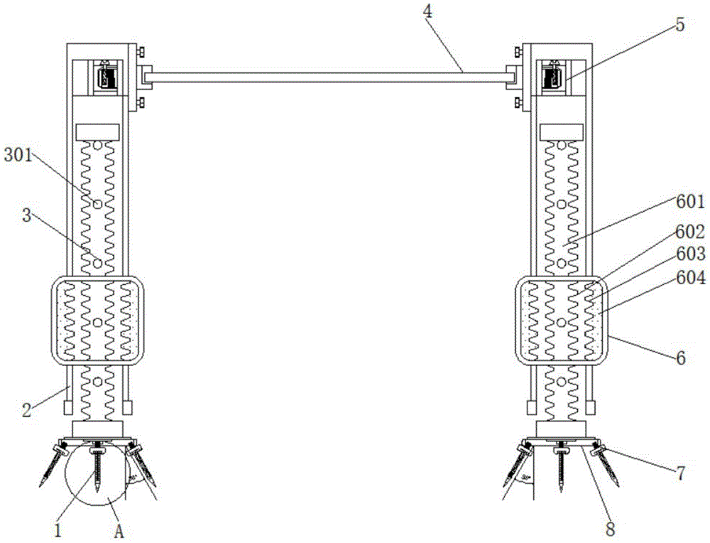
Referring to fig. 1-5, the present invention provides an embodiment: a safe scaffold with a locking function for civil engineering comprises a shell 2, a limiting structure 3, a connecting structure 5 and a lifting structure 6, wherein the connecting structure 5 is movably connected to both sides of a connecting rod 4;
a connecting clamping block 501, a connecting clamping groove 502, a fixed clamping block 503, a fixed clamping groove 504, an external thread 505 and an internal thread 506 are sequentially arranged in the connecting structure 5, one side of the connecting clamping block 501 is movably connected with the connecting clamping groove 502 matched with the connecting clamping block 501, the fixed clamping groove 504 is embedded in the top end of the connecting clamping groove 502, the fixed clamping block 503 penetrates through the top end of the fixed clamping groove 504, the external thread 505 is welded at the top end and the bottom end of the connecting clamping block 501, and the internal thread 506 matched with the external thread 505 is welded at the top end and the bottom end of the connecting clamping groove 502;
specifically, as shown in fig. 1 and fig. 3, when the mechanism is used, firstly, the connecting structures 5 on both sides of the connecting rod 4 achieve the effect of convenient installation and disassembly, and are convenient to move, the working principle of the connecting structures 5 is that the connecting structures are fixed through the connecting fixture blocks 501 and the connecting fixture grooves 502, and the fixing fixture blocks 503 and the fixing fixture grooves 504 are clamped from different directions, so as to achieve the effect of strengthening the fixing;
the bottom end of the connecting structure 5 is fixedly connected with the shell 2, and the bottom end of the connecting structure 5 is fixedly connected with the lifting structure 6;
the lifting structure 6 is internally provided with a lifting rod 601, a movable fixture block 602, a movable clamping groove 603 and a hand-held knob 604 in sequence, the lifting rod 601 penetrates through the top end and the bottom end of the hand-held knob 604, the movable fixture block 602 is welded on two sides of the lifting rod 601, and the movable clamping groove 603 matched with the movable fixture block 602 is welded on two sides of the hand-held knob 604;
specifically, as shown in fig. 1 and 3, when the mechanism is used, firstly, the lifting structure 6 inside the housing 2 achieves the effect of lifting and height adjustment, and the structure can be adjusted by a user according to actual needs, which is more convenient, and the working principle of the lifting structure 6 is that the lifting rod 601 embedded with the mobile clamping groove 603 and the mobile clamping block 602 matched with the mobile clamping groove 603 are driven to lift and jack upwards by rotating the hand holding knob 604, so that the housing 2 is jacked upwards;
the top end and the bottom end of the lifting structure 6 are respectively embedded with a limiting structure 3, a limiting clamping groove 301, an anti-skid thread 302, a limiting clamping block 303 and a fixing knob 304 are sequentially arranged in the limiting structure 3, one side of the fixing knob 304 is fixedly connected with the limiting clamping block 303, one side of the limiting clamping block 303 is fixedly connected with the anti-skid thread 302, and one side of the limiting clamping block 303 is movably connected with the limiting clamping groove 301 matched with the limiting clamping block 303;
specifically, as shown in fig. 1 and 3, when the mechanism is used, firstly, the top end and the bottom end of the lifting rod 601 are uniformly penetrated with the limiting clamping grooves 301, and the structure has the advantages that the limiting clamping grooves are matched with the limiting clamping blocks 303 embedded on the fixing knob 304 to achieve the clamping and fixing effect, and the height of the shell 2 is adjusted;
the bottom end of the lifting structure 6 is fixedly connected with a bottom plate 8, and the bottom end of the bottom plate 8 is fixedly connected with a dismounting structure 7;
a dismounting clamping block 701, a dismounting clamping groove 702, an anti-skid block 703 and an anti-skid groove 704 are sequentially arranged in the dismounting structure 7, the dismounting clamping block 701 is movably connected to the bottom end of the dismounting clamping groove 702, the anti-skid block 703 is embedded in the outer side of the dismounting clamping block 701, and the anti-skid groove 704 matched with the anti-skid block 703 is embedded in the inner side of the dismounting clamping groove 702;
specifically, as shown in fig. 1 and 3, when the mechanism is used, firstly, the fixed steel needle 1 is detached through the structure, the working principle of the detaching structure 7 is that the detaching fixture block 701 and the detaching fixture groove 702 are connected in a clamping manner, and the anti-skid block 703 and the anti-skid groove 704 achieve the fixing and limiting functions;
the bottom end of the bottom plate 8 is provided with the fixed steel needles 1, the fixed steel needles 1 are distributed along the circle center of the bottom plate 8 in an annular array, and the fixed steel needles 1 are inclined at 30 degrees along the central axis of the bottom plate 8;
specifically, as shown in fig. 1 and 2, when the mechanism is used, firstly, because the device is mainly used on soft ground, the fixing steel needle 1 arranged at the bottom end of the bottom plate 8 plays a role of fixing the device, the structure has the advantages that the device can be erected, the structure is simple, the cost is low, the device can be fixed only by applying downward force and pressing in use, the working principle of fixing the steel needle 1 is that the bottom end is in an outward 30-degree expansion shape, and the design is more labor-saving.
The working principle is as follows: when in use, the device is mainly used on soft land, so the fixed steel needle 1 arranged at the bottom end of the bottom plate 8 achieves the effect of fixing the device, the structure has the advantages of standing the device, simple structure and low cost, the device can be fixed only by downward force application and compression when in use, the fixed steel needle 1 adopts the working principle that the bottom end is in an outward 30-degree expansion shape, the design can save more labor, the lifting structure 6 in the shell 2 achieves the effect of lifting and height adjustment, the structure can be conveniently adjusted by a user according to actual needs, and more convenience is achieved, the working principle of the lifting structure 6 is that the knob 604 is held by a hand in a rotating way, so that the internally embedded movable clamping groove 603 drives the lifting rod 601 embedded with the movable clamping block 602 matched with the movable clamping groove 603 to lift upwards, and the shell 2 lifts upwards, the top and the bottom of lifter 601 evenly run through there is spacing draw-in groove 301, the advantage of this structure lies in utilizing the spacing fixture block 303 of inlaying with fixed knob 304 to reach the block fixed, the effect of adjustment casing 2's height, the connection structure 5 of the both sides of connecting rod 4 reaches convenient to install and dismantle's effect, be convenient for remove, connection structure 5's theory of operation is fixed through connecting fixture block 501 and connecting draw-in groove 502, fixed fixture block 503 and fixed draw-in groove 504 are through following the direction joint of difference, reach and strengthen fixed effect.
It is obvious to a person skilled in the art that the invention is not restricted to details of the above-described exemplary embodiments, but that it can be implemented in other specific forms without departing from the spirit or essential characteristics of the invention. The present embodiments are therefore to be considered in all respects as illustrative and not restrictive, the scope of the invention being indicated by the appended claims rather than by the foregoing description, and all changes which come within the meaning and range of equivalency of the claims are therefore intended to be embraced therein. Any reference sign in a claim should not be construed as limiting the claim concerned.